Abstract
Catheter-based treatment of structural heart diseases (SHD) has seen tremendous advances in the past decades, thanks to the development of new devices and advances in imaging techniques. Today, we have an extensive armamentarium of imaging tools for preprocedural planning, intraprocedural guidance and follow-up of SHD. Intraprocedural guidance is based mainly on transoesophageal echocardiography; however, other imaging modalities are used as complementary or alternative techniques, each of them with its strengths and weaknesses. Thus, a multimodality imaging approach provides added values in this setting. As the field of imaging parallels the continuous technical improvements, this review will describe the state of the art imaging techniques, focusing on echocardiography during procedural guidance of the most common catheter-based interventions, providing tips and tricks for interventional cardiologists: in particular, how to guide transseptal crossing; left atrial appendage closure; transcatheter mitral or tricuspid valve repair or replacement; percutaneous closure of patent foramen ovale and atrial defects; and percutaneous closure of paravalvular leaks. Open challenges for the near future are the need for physicians with specific technical skills and competencies in SHD imaging, more attention to high levels of radiation exposure, and optimisation of intraprocedural and post-procedural evaluation.
Introduction
The past two decades have seen tremendous advances in the catheter-based treatment of structural heart diseases (SHD) thanks to the development of new devices with improved performance and advances in imaging techniques.
Cardiac imaging in the catheter-based treatment of SHD has come a long way in the past 70 years (Figure 1). Indeed, since the pioneering work by Rubio-Alvares and Limon in 1952 to relieve critical pulmonic valve stenosis, when a simple chest X-ray was the only modality allowing visualisation of the heart, a cascade of procedural and technological advances has followed1. Transthoracic echocardiography (TTE) first appeared in the cath lab in the 1980s2. Two-dimensional (2D) transoesophageal echocardiography (TOE) started to be developed in the late 1970s and made its first appearance as intraprocedural imaging guidance in 199034. Throughout the past three decades, TOE technology has progressed from single-plane to three-dimensional (3D) transducers. It has become the leading preprocedural and intraprocedural cardiac imaging modality in SHD interventions. At the same time, other alternative/complementary imaging tools to conventional TOE have been developed and introduced, such as the micro TOE probe and intracardiac echocardiography (ICE)56. The micro TOE probe (S8-3t microTOE probe [Philips Healthcare]; ClariTEE [ImaCor]) can be introduced transorally or transnasally using local anaesthesia only, and offers sufficient image quality compared to conventional TOE and ICE. Promising results have been reported to guide transseptal puncture (TSP) and left atrial appendage (LAA) closure6. ICE may have some advantages over TOE: it is more comfortable for the patient, avoids the use of general anaesthesia and potentially allows a single-operator procedure. In recent years, advances in technology have allowed the development and successful implementation of real-time 3D ultrasound in ICE, which is crucial for applications in SHD procedures such as TSP, LAA closure, transcatheter tricuspid interventions, etc.
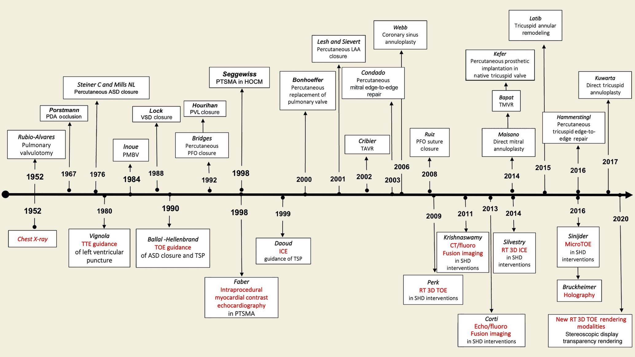
Figure 1. History and evolution of SHD intervention and interventional imaging.ASD: atrial septal defect; CT: computed tomography; HOCM: hypertrophic obstructive cardiomyopathy; ICE: intracardiac echocardiography; LAA: left atrial appendage; PDA: patent ductus arteriosus; PFO: patent foramen ovalis; PMBV: percutaneous mitral balloon valvuloplasty; PTSMA: percutaneous transluminal septal myocardial ablation; PVL: paravalvular leak; RT: real time; SHD: structural heart disease; TAVR: transcatheter aortic valve replacement; TMVR: transcatheter mitral valve replacement; TOE: transoesophageal echocardiography; TSP: transseptal puncture; TTE: transthoracic echocardiography; VSD: ventricular septal defect.
Today, we undoubtedly have an armamentarium of imaging tools providing excellent imaging quality. However, each of them has its strengths and weaknesses. Therefore, multimodality imaging utilising several imaging techniques together may provide added value in terms of procedural planning and efficacy by combining the individual strength of each imaging modality. Recently, fusion imaging as a combined “hybrid” procedure of several imaging modalities has gained attention78. Its major advantages include the optimised multidimensional view with an excellent spatial resolution, anatomic orientation, visualisation of soft tissue onto fluoroscopic view, allowing better procedural navigation with fluoroscopy and with less use of contrast medium.
The last frontier of interventional imaging is to overcome the way 3D images are displayed and to increase the ability of interacting with them. The images acquired are usually presented on 2D displays, thereby limiting their usefulness and the ability to interact with them. Holographic images, created in real time from the volumetric data, which float in the air during the procedurein front of the operator and above the patient, could provide an intuitive and interactive display for the interventionalist, and may improve procedure outcomes9.
This review will describe the use of imaging techniques, focusing attention on echocardiography during procedural guidance of the most common catheter-based interventions of SHD, providing some tips and tricks for the practical interventional cardiologist (Central Illustration).
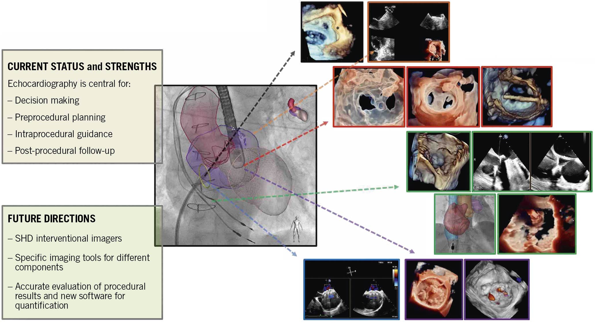
Central illustration. Echocardiographic guidance for transcatheter structural cardiac interventions.
Transseptal puncture
The transseptal crossing is the common front door for many left-side catheter-based procedures. Experienced operators may safely perform a TSP using only fluoroscopy. On the other hand, imaging guidance mainly performed by TOE is mandatory for a targeted/site-specific TSP for the majority of structural interventions, and it is also helpful during the initial phase of training.
Procedural steps and imaging guidance
The interatrial septum (IAS) may be displayed by fluoroscopy and TOE in different anatomical projections and perspectives to define the optimal target for TSP (Figure 2)10.
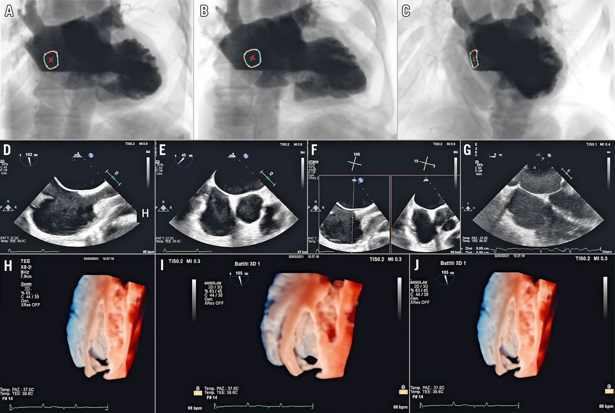
Figure 2. Recommended imaging modalities to display IAS. A) Anteroposterior projection: the IAS is displayed in an oblique perspective corresponding to the 3D oblique perspective from right atrium (H). B) Right anterior oblique projection: the IAS is displayed in en face perspective, corresponding to the 3D en face view from the right atrium (I). C) Left anterior oblique projection: the side-on profile of the IAS corresponding to either the 3D lateral perspective (J) or 2D bicaval view (90-120°) (D). D) Superior-inferior orientation. E) Short-axis (SAX) view at the base (30-50°) for anterior-posterior orientation. F) Biplane view that displays both the bicaval and the SAX view simultaneously. G) Four-chamber view (0°) to determine the height above the mitral valve.
The procedural steps are described in Figure 3 and Supplementary Table 1.
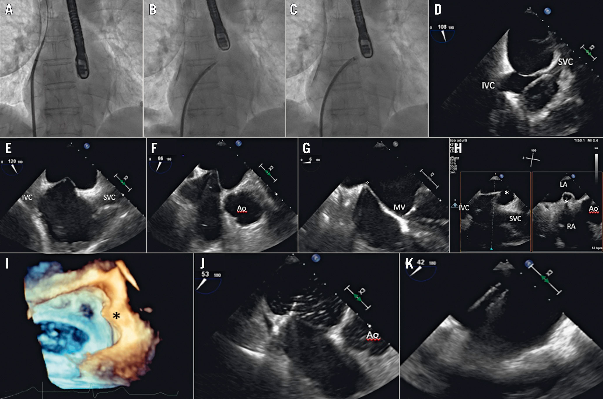
Figure 3. Procedural steps of TSP. A - C) Anteroposterior fluoroscopic projection showing the progressive steps of the TSP. A) Guidewire in the SVC. B) The catheter and needle in the FO and then the septum is punctured. C) The septum is crossed and the needle is removed. D) 2D TOE mid-oesophageal bicaval view showing the catheter tip coursing from the SVC to the FO. E- H) Sequential 2D TOE views showing the “tenting” of the catheter against the FO. I) 3DE overhead view showing the septum and the tenting (asterisk) in lateral perspective. J) Septal crossing confirmed by the transient appearance of bubbles in the LA. K) Catheter in the LA.3DE: three-dimensional echocardiography;Ao: aorta; FO: fossa ovalis; IVC: inferior vena cava; LA: left atrium; MV: mitral valve; RA: right atrium; SVC: superior vena cava;TOE: transoesophageal echocardiography.
TOE is of the utmost importance to identify complications promptly, e.g., cardiac perforation (right and/or left atrium or the aorta), thrombus formation, or ST-segment elevation (due to air embolism in the right coronary).
Fusion imaging can provide added value during TSP as follows (Figure 4A-Figure 4D)11. 1) No predefined fluoroscopic angulation is anatomically consistent in all patients. Thus, fusion imaging may be useful for achieving a patient-tailored fluoroscopic view. 2) The catheter and the fossa ovalis (FO) are simultaneously visualised on the fluoroscopic screen, allowing operators to understand the spatial position of the catheter according to superior-inferior and anterior-posterior directions. 3) The downwards pull of the catheter towards the IAS can be monitored by the 2D bicaval view superimposed on the left anterior oblique (LAO) projection, in which the side-on profile of the IAS is well visualised and the tenting can be clearly appreciated. Alternatively, the tenting can be looked for by cropping a 3D volume dataset until the tenting becomes visible in the lateral perspective.
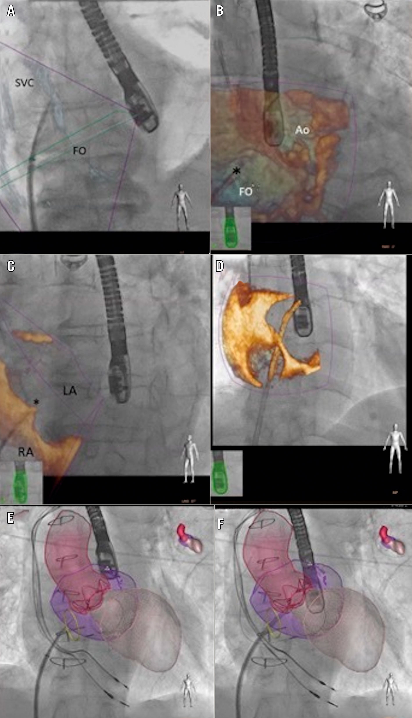
Figure 4. Fusion imaging guidance of TSP. A) Patient-tailored anteroposterior (AP) fluoroscopic view “fused” with a 2D bicaval view of the IAS, showing the dilator coursing from the SVC to the FO. B) AP fluoroscopic view “fused” with a 3D en face view of theIAS from the RA, showing the fine position of the catheter tip into the FO. C) 3D lateral perspective of the IAS superimposed on an AP fluoroscopic projection showing the tenting (*). D) 3D oblique perspective of the IAS superimposed on an AP fluoroscopic view showing septal crossing. E) & F) Heart models obtained from 3D data sets and superimposed on the fluoroscopic view. The FO is identified by a yellow circle.Ao: aorta; AP: anterioposterior; FO: fossa ovalis; LA: left atrium; RA: right atrium; SVC: superior vena cava.
In addition, there are options to superimpose onto the fluoroscopic view the anatomical models of relevant structures based on a co-registered TOE sequence (Figure 4E, Figure 4F).
Left atrial appendage closure
LAA closure aims to prevent stroke in patients with non-valvular atrial fibrillation by excluding the LAA from systemic circulation. Echocardiographic imaging is of paramount importance for correct procedural planning, safety and procedural success.
Procedural planning
2D and 3D TOE has traditionally been the cornerstone of preprocedural evaluation and procedural planning for LAA closure. It allows an accurate description of the morphological features of the LA and the LAA, measurement of the dimensions of the ostium and the length of LAA, assessment of the number and configuration of its lobes and the presence of intraluminal thrombi, as well as providing relevant information on the surrounding structures12 (Figure 5).
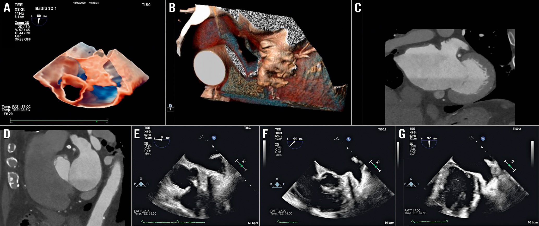
Figure 5. Recommended imaging modalities to evaluate the anatomy of the LAA. A) 3D TOE transparency rendering. B) 3D CT volume rendering. C)CT coronaland sagittal (D) reconstructions. E– G) Set of 2D TOE views ranging from 0-to-135°.LAA: left atrial appendage; TOE: transoesophageal echocardiography
Computed tomography (CT) has been increasingly used for preprocedural evaluation of LAA closure due to its high spatial resolution. Thanks to 3D volume rendering and multiplanar reconstruction (MPR), the interventionalist is not only able to reconstruct the three-dimensional anatomy of the pertinent structures and obtain precise LAA ostial dimensions, but can also calculate the most convenient fluoroscopic projections to use during the procedure, and potentially spare X-ray exposure and contrast medium usage. Moreover, CT is highly sensitive in excluding the presence of intraluminal filling defects13.
In order to select the proper device, the LAA dimensions and morphology need to be thoroughly assessed during the preprocedural planning, and confirmed intraprocedurally after ensuring adequate volume repletion of the patient to avoid undersizing of the device14. Device sizing is calculated using different segments according to the type of the device (Figure 6). However, the dimensions of the LAA ostium (the most proximal portion of the LAA, defined by an imaginary line connecting the axial image of left circumflex artery and the most proximal portion of the Marshall band), the neck (the tubular portion of the LAA approximately 1 cm distalto the ostium) and the depth of the LAA are the parameters necessary for appropriate device sizing. Any proximally originating lobes or accessory lobes and trabeculations should be reported as they may interfere with the device positioning guidance and mislead the interventionalist to attempt to release the device more distally or proximally than usual.
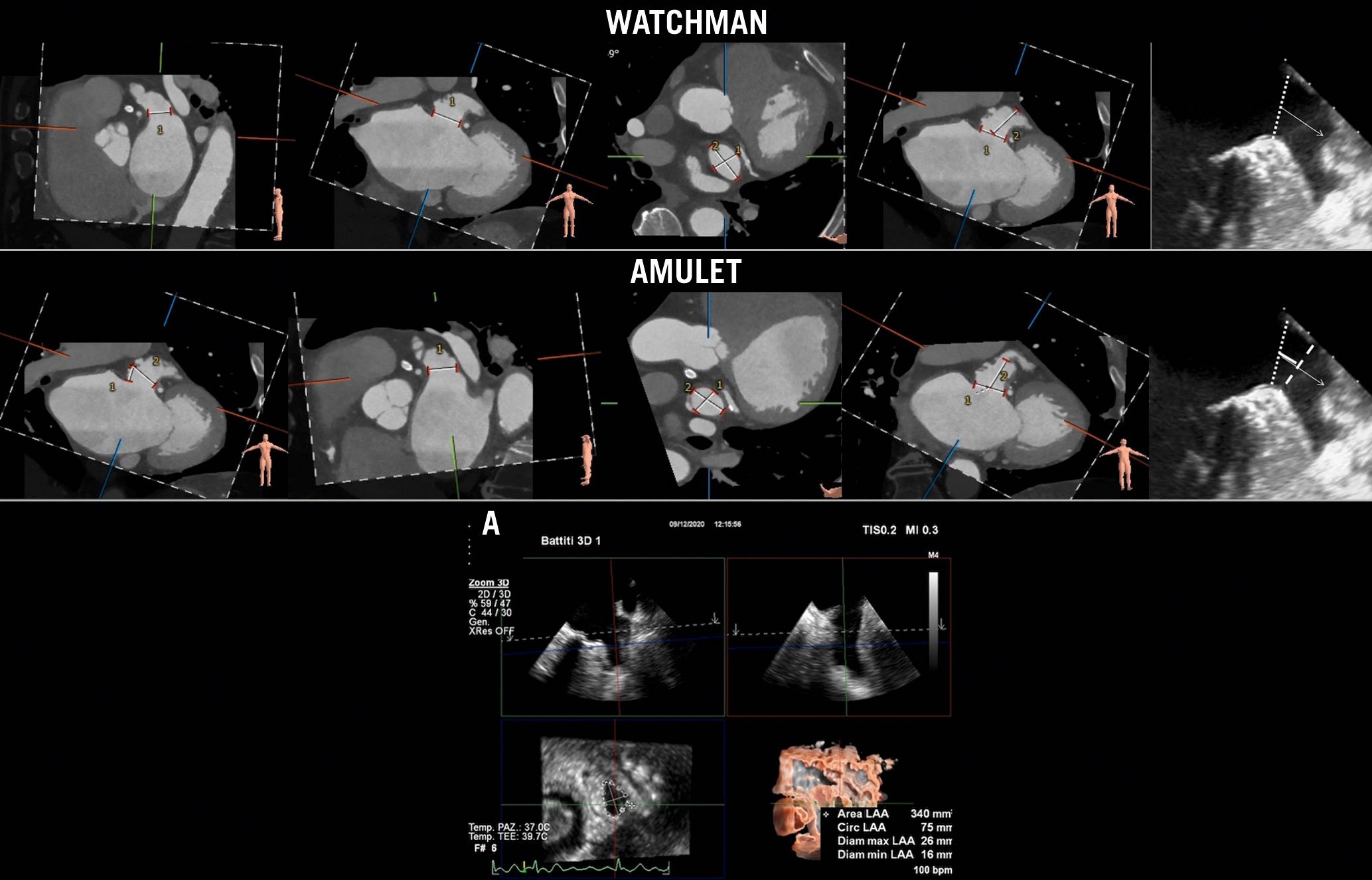
Figure 6. Recommended imaging modalities for LAA sizing. The WATCHMAN device (Boston Scientific) size is chosen based on the dimensions of the LAA ostium (dotted line in TOE view) and the depth of the appendage. For the AMPLATZER Amulet device (Abbott Laboratories),the device landing zone is 1 cm distally from the LAA ostium (dashed line in TOE view). A) 3D TOE semi-automated measurement of LAA sizing based on MPR algorithm.LAA: left atrial appendage; MPR: multiplanar reconstruction; TOE: transoesophageal echocardiography
Procedural steps and imaging guidance
The procedure is usually guided by fluoroscopy and TOE; ICE can be usedinstead of TOE in selected cases.
The sequential steps are described in Figure 7 and Supplementary Table 2.
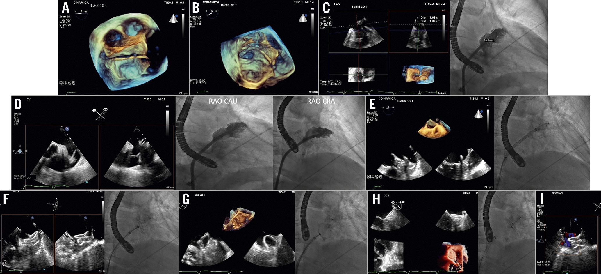
Figure 7. LAA closure procedural steps (AMPLATZER Amulet device). A) Navigation inside the LAA with wire and catheter (3D overhead of the LAA). B) LAA engagement by the wire (3D en face view of LAA). C) Echocardiographic and angiographic LAA sizing. D) Implant projections: TOE views 0°-60°corresponding to RAO cranial view and 120°-135 corresponding to RAO caudal view. E) Lobe expansion. F) Disc opening. G) Tug test. H) Release and final result. I) Leak evaluation.CAU: caudal; CRA: cranial; LAA: left atrial appendage;RAO: right anterior oblique; TOE: transoesophageal echocardiography
TSP (performed as previously described) is required to access the LA. An inferior and posterior puncture site may normally facilitate the manoeuvres towards the LAA. However, a perfect alignment between the TSP needle and the LAA is desirable but not mandatory, as a correction of the trajectory is normally possible by manoeuvring the device delivery system. Entering the LA through a patent foramen ovale (PFO) is generally not advisable due to an unfavourable trajectory, thus the interventionalist should be informed if PFO crossing is suspected. After access to the LA is obtained, the LAA can be angiographically imaged by power injections through the pigtail catheter.
For the subsequent manoeuvres of stiff guidewire and delivery sheathpositioning, right anterior oblique (RAO) projections at approximately 40° or RAO caudal (CAU) 20°projection (usually the one that best depicts the LAA) ischosen.
After the device has been released, echocardiography allows checking for correct device placement according to device-specific criteria. The residual leak in the LAA can be assessed with colour Doppler by lowering the Nyquist limit to 20-30 cm/sec15. Conventionally, a jet flow ≥5 mm will be considered significant and might prompt device resheathing and repositioning15.
Fusion imaging seems helpful during all steps of the LAA occlusion procedure in terms of radiation exposure and fluoroscopy timeand avoids continuous probe manipulation (Figure 8A-Figure 8C)1617.
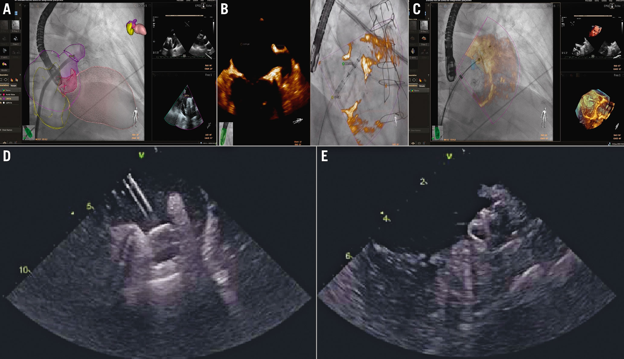
Figure 8.LAA closure procedural steps. A – C) Fusion imaging and D-E) ICE guidance. A) Heart model. Catheter inside the LAA. B& C) LAA is displayed in 3D rendering. B) Lobe expansion. C) Disc opening. D& E) ICE guidance during LAA occlusion. The ICE probe in the left atrium is showing the device on the delivery cable (D) and the device in its final position (E).ICE: intracardiac echocardiography; LAA: left atrial appendage
ICE provides intracavitary images of the LAA. From the baseline “home view”, the probe can be manoeuvred posteriorly to image the IAS and guide the TSP. Although imaging the LAA with the ICE probe in the right atrium, coronary sinus, right ventricle or in the pulmonary artery is possible18, in order to obtain adequate pictures the ICE probe needs to be positioned in the LA. ICE can be introduced using two separate TSP punctures or, more often19, if a single TSP technique is used, the delivery sheath is used to dilate the TSP and the ICE catheter is advanced in the LA along the stiff guidewire20. The LAA can then be imaged from various positions within the LA for procedural guidance (Figure 8D, Figure 8E). If intraprocedural ICE is used and preprocedural TOE avoided, the patient should undergo preprocedural CT evaluation before the procedure for a completely TOE-free procedure.
Follow-up
The patient usually undergoes a TTE before discharge in order to check for possible complications such as pericardial effusion or mitral valve (MV) damage. The occluder device might be indirectly visualised inside the LA as a metallic artefact21. No consensus or guidelines are available regarding the imaging follow-up after an LAA closure procedure (modality and frequency). Usually, imaging follow-up is performed by TOE,however, CT is also useful for post-procedural surveillance22. Follow-up involves checking for the correct position of the device, the formation of atrial-side device residual leak (patency) into the LAA, device embolisation andpericardial effusion. It should be noted that CT appears more sensitive than TOE in detecting leaks after device implantation23.
Transcatheter mitral valve interventions
Transcatheter mitral valve interventions (TMVI), either repairing or replacing the MV, are established alternative options for patients with mitral regurgitation (MR)who are not suitable for conventional open heart surgery. Available transcatheter therapeutic options are:
–Leaflet repair: an edge-to-edge repair procedure which mimics the surgical one by approximating MV leaflets together at the site of regurgitation.
–Chordal repair: adjustable transapical beating-heart artificial chordal implantation.
–Annular repair: percutaneous direct or indirect annuloplasty aiming to reduce annular dimensions and improve leaflet coaptation.
–MV replacement.
Preprocedural evaluation
Preprocedural evaluation aims to evaluate MR severity and the functional anatomy of the MV in order to choose the best therapeutic option. In particular, leaflet repair is mainly indicated in functional MR due to leaflet tethering or degenerative MR, chordal implantation in patients with leaflet prolapse, annuloplasty devices for functional MR due to annular dilatation and, in case of complex mechanisms not suitable for MV repair, MV replacement may be an alternative option24.
TTE is the first-line imaging technique to rule out potential candidates for percutaneous intervention. In case of possible suitability for TMVI, TOE is mandatory to evaluate carefully the MV anatomy and the mechanism of regurgitation. In addition, for therapeutic approaches targeting the annulus, and for MV replacement, CT evaluation is mandatory for annular sizing and evaluating morphological characteristics in terms of calcifications, spatial relationships with surrounding structures, and the risk of left ventricular outflow tract (LVOT) obstruction.
Transcatheter leaflet approximation
Two devices are currently available: MitraClip (Abbott Laboratories) and PASCAL devices (Edwards Lifesciences).
Echocardiographic assessment of functional anatomy and determination of the mechanism of MR are mandatory for patient selection. Based on the morphologic characteristics of the MV, we may identify potential candidates foredge-to-edge MV repair with different favourable/unfavourable features (Supplementary Table 3).
Procedural steps and imaging guidance
Under general anaesthesia, echocardiography and fluoroscopy guide the procedural steps (Figure 9, Figure 10, Supplementary Table 4).
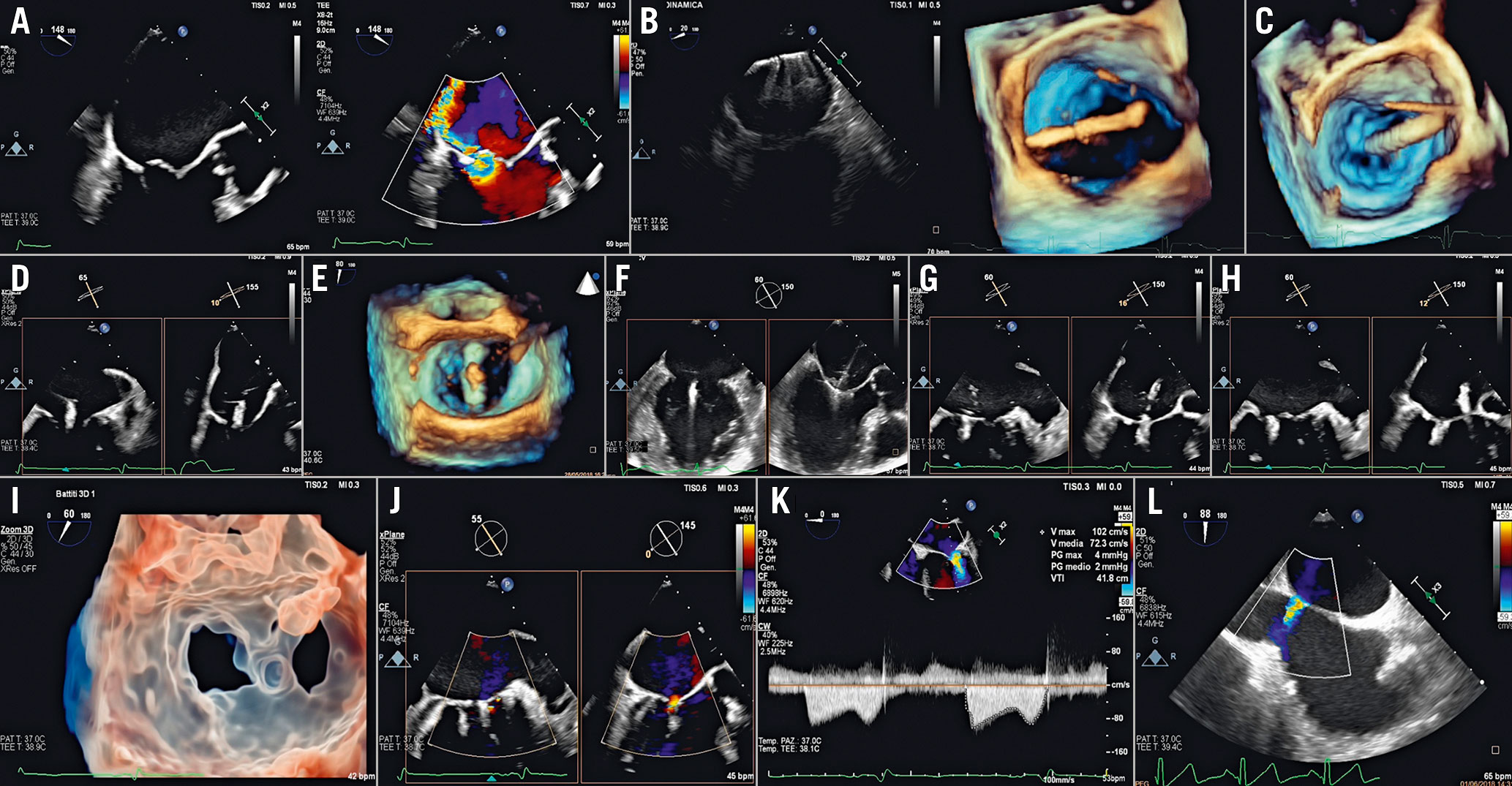
Figure 9. MitraClip procedural steps. A) Baseline evaluation. B) Clip extrusion into the LA. C) Steering of the CDS towards the MV plane. D) Trajectory. E) Clip arm orientation. F) Clip advancement into the LV and leaflet grasping. G) Assessment of leaflet insertion. H) Clip release. I) 3D transparency rendering en face view of the MV showing the double orifice clearly. J) Final result. K) Transmitral gradient. L) Residual ASD evaluation. ASD: atrial septal defect;CDS: clip delivery system; LA: left atrium; LV: left ventricle; MV: mitral valve
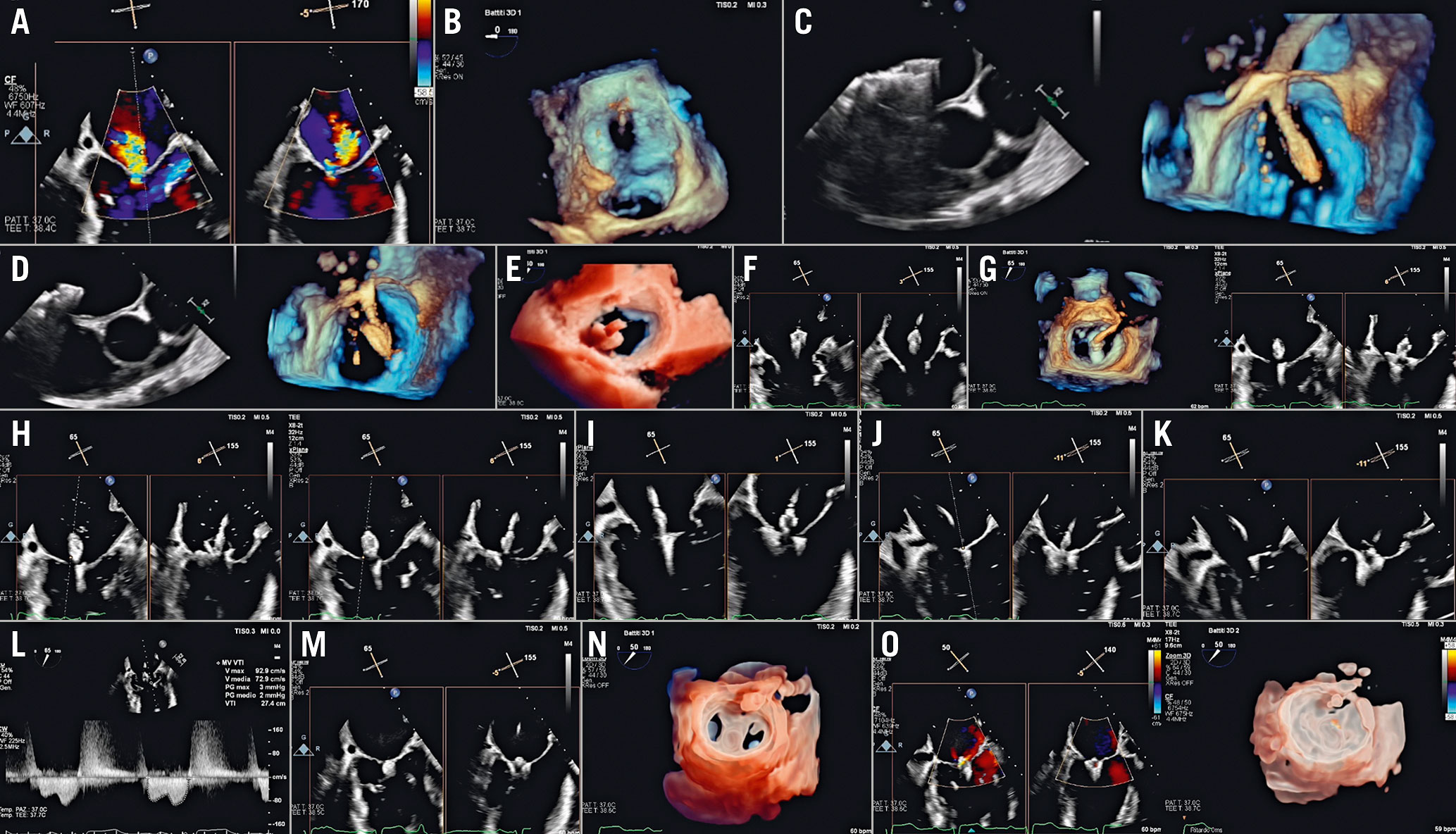
Figure 10. PASCAL procedural steps. A) Baseline evaluation. B) Parallelism test to ensure guide sheath tip flexes parallel to MV (3D en face view of the septum). C & D) implant system insertion: (C) implant elongated, and (D) implant closed. E) Steering towards the MV plane. F) Implant trajectory and positioning. G) Implant orientation. H) Identification of anterior and posterior clasp. I) Crossing valve. J) Leaflet capture. K) Implant closing. L) Transmitral gradient. M) Implant release. N) 3D transparency rendering en face view of MV showing the double orifice clearly. O) Post-implant release evaluation.MV: mitral valve
1. The TSP needs to be tailored to the procedure: usually it should be in the inferior-posterior aspect of the fossa ovalis. Moreover, lower TSP sites are required for lateral regurgitant jets, while higher ones are needed for medial jets in order not to fall below the MV when deflecting the system. The guide catheter is then inserted into the LA. Disappearance of tenting on the IAS is an indicator of complete crossing: the dilator can be removed when the guide catheter is at least 2 cm across the IAS. Afterwards, the delivery system is advanced into the LA.
2. The system is then steered towards the MV over the target lesion. The trajectory should ensure perpendicularity to the MV plane: misalignment can affect both the symmetry and efficacy of the grasping.
3. Perpendicularity is usually guided in biplane imaging (commissural and long-axis view) and should be achieved in both views. Once the appropriate axial alignment is achieved over the target lesion, the device arms are opened and oriented perpendicularly to the coaptation line.
4. The system is then advanced below the MV with arms partially open (60°) and with the paddles fully open in the MitraClip and PASCAL procedure, respectively. Once below the MV plane, the arms are fully opened, and correct positioning and orientation is rechecked as the implant may rotate when crossing the MV. Inside the left ventricle (LV), any needed changes in the orientation of the arms should be minimal; in case of significant orientation adjustment, the device should be inverted and withdrawn back into the LA. By retracting the system back, once both leaflets are visualised over the arms, the grippers are lowered down and leaflets grasped. If the implant appears properly positioned, the implant can be fully closed.
5. Adequate leaflet insertion is evaluated by direct and indirect signs. The best result should be a balance between iatrogenic stenosis and adequate reduction of MR, without distortion of the coaptation line. An MV area ≤1.5 cm2 and a transmitral pressure gradient >5 mmHg indicate significant mitral stenosis25. Once the result is satisfactory, the device is detached from the delivery system.
The evaluation of residual MR after edge-to-edge is very challenging. The evaluation of residual MR should be performed under haemodynamic conditions similar to baseline using a multiparametric approach and classified in a 4-grade system (1+ to 4+)2627 (Supplementary Table 5).
6. After release of the device, the delivery catheter is withdrawn into the guide catheter, which is maintained in the LA, as a second clip implantation may be required. If no additional clip is needed, the system can be removed. After system removal, the residual shunt and size of iatrogenic atrial septal defect (ASD) should be evaluated. The defect is usually clinically insignificant28.
TOE is fundamental to recognise complications promptly, e.g., intracardiac thrombosis on devices, cardiac tamponade, worsening of MR (leaflet or chordal damage, loss of leaflet insertion or partial clip detachment) and iatrogenic mitral stenosis.
ICE could be an alternative imaging tool in case of contraindication to TOE, althoughexperience is limited29. TSP guidance may be performed with the catheter in the right atrium, while the remaining procedural steps require the position of the catheter in the mid-right ventricle and the outflow tract. ICE images allow good visualisation especially of the central portion of the valve and they are useful to detect complications.
Although this procedure is effectively guided by 2D/3D TOE and fluoroscopy, echocardiographic-fluoroscopic fusion imaging may potentially have additional value (Figure 11)303132. Fusion imaging may be helpful in:
–Guiding TSP
–Navigating into the LA
–Assessing device trajectory and alignment
–Co-localising the regurgitant jet
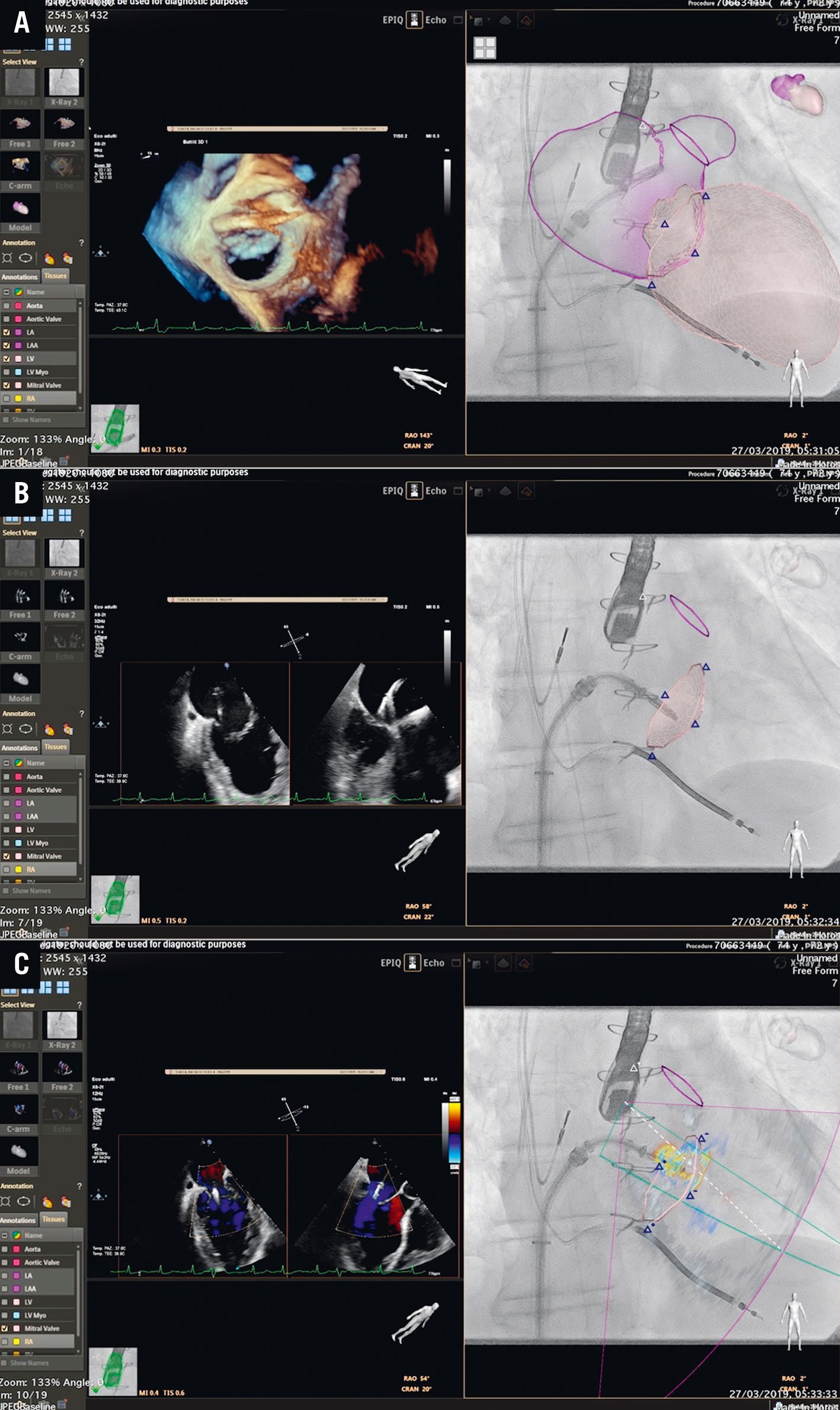
Figure 11. Fusion imaging with heart model in the MitraClip procedure - essential steps. A) Navigation into the LA. B) Steering and positioning the DC towards the MV. C) The jet is displayed on the fluoroscopic screen and used as a reference marker (target lesion).
Transcatheter annuloplasty
Direct annuloplasty
The Cardiobandevice (Edwards Lifesciences) is an incomplete adjustable surgical-like Dacron band, transseptally delivered, implanted on the posterior annulus from the anterolateral to posteromedial commissure.
The procedure is heavily dependent on pre-interventional screening based on echocardiography and CT scan, in order to assess: (i) technical feasibility, based on the relationship between circumflex artery and posterior annulus;(ii) annulus sizing and thickness; and(iii) the anatomy of the LA and IAS. Preprocedural CT also provides the coordinates for the procedure and the expected fluoroscopic projections.
Intraprocedural monitoring
The optimal site for the TSP is predefined by CT planning, providing distances from the muscular part, from the aorta, and the height measured from the annular plane (>3.5 cm from the annular plane).The puncture site must be straight above the posteromedial commissure.
The sequential steps are described in Figure 12, Supplementary Table 6.
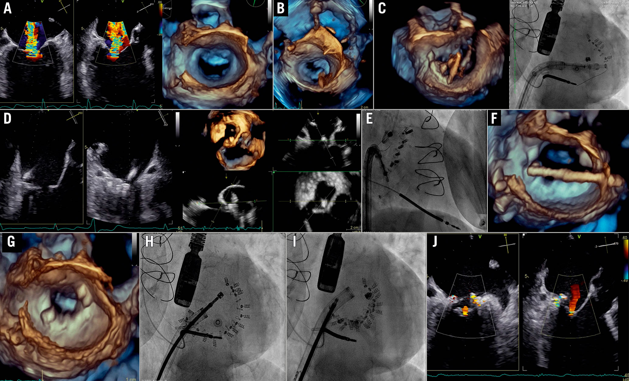
Figure 12. Cardioband procedure in the mitral valve. A) Baseline evaluation. B) TSP: overhead perspective of the LA showing tenting with respect to the posteromedial commissure. C) System navigation around the target zone guided by 3D perspectives and LAO CAU fluoroscopic projection. D) Visualisation of the contact of IC with the annulus by biplane view and MPR. E) RAO projection used for implant and pull test. F) Size adjustment tool (SAT) insertion. G) 3D en face view of MV after SAT removal showing the implant asan incomplete surgical annuloplasty. H) LAO before cinching. I) After cinching. J)Final result.IC: implant catheter; LA: left atrium MPR: MV: mitral valve; TSP: transseptal puncture
The steering and navigation of the implant delivery system along the posterior annulus is guided by different 3D perspectives and the fluoroscopic LAO CAU view. After reaching the target point, RAO projection, several 2D and biplane views or MPR are used to assess the proper distance from the hinge point of the posterior leaflet and the device angulation for fine adjustment, and for checking proper anchoring via a push-and-pull test. Coronary angiography rules out the risk of injury to the circumflex artery.
The first anchor should be positioned as anterior as possible and close to the anterolateral trigone. The Cardioband implant is navigated to the next anchoring point along the posterior annulus until it reaches the posterior trigone. After the last anchor deployment and disconnection of the device, the size adjustment tool is inserted and connected to the spool of the implant, that is then contracted while reduction of MR severity and annulus size are monitored.
A multiparametric approach provides the most appropriate method to characterise and quantify residual MR, the possible iatrogenic stenosis,and the mitral annular remodelling.
Fusion imaging may be helpful in the different procedural steps:
–TSP
–Navigation within the LA - the perimeter of the annulus is visible on the fluoroscopy
–Implant deployment - correct orientation of the catheter with respect to the annular plane and its position in relation to the leaflets hinge - relationship between tissue, anchors and coronary artery
– Implant size adjustment/cinching - modification of annular size taking into account both the reduction of the distance among the radiopaque anchors and the reduction of the annular tissue
Tricuspid transcatheter interventions
Indications
Tricuspid regurgitation (TR) is a frequent finding on routine echocardiography. In the Framingham Heart Study it was present in more than 80% of the cohort33. The prevalence of more than moderate TR increases with ageing, reaching up to 1.5% in men and 5.6% in women over seventy. A mild degree is considered benign, but moderate and severe TR are associated with worse outcome. The optimal timing of intervention remains unclear, although it should be carried out sufficiently early to avoid irreversible right ventricular (RV) dysfunction34.
In severe primary TR, surgery is not only recommended in symptomatic patients but also in asymptomatic patients when progressive RV dilatation or decline in RV function occurs. In severe secondary TR, tricuspid repair during left-sided surgery has been demonstrated to provide reverse RV remodelling and improvement of functional status. To improve the prognosis, the treatment of severe late TR following left-sided valve surgery should be considered earlier, even in asymptomatic patients, if there are signs of progressive RV dilatation or decline in RV function.
Surgical tricuspid valve (TV) annuloplasty is the gold standard in many cases. Although well-established risk models exist for several other cardiac operations, no well-established risk model exists for the performance of isolated TV operations. The only available score has been proposed by LaPar et al35, who developed parsimonious clinical risk models for operative mortality and major morbidity after isolated TV operations. The factors most strongly associated with mortality include preoperative haemodialysis requirement, advanced lung disease, NYHA Functional Class and performance of emergent operations, highlighting the central clinical message that early referral for the performance of TV operations has the potential to reduce surgical mortality and morbidity for these patients35.
Several transcatheter techniques are currently in bench and early clinical testing as alternative options. The number of patients treated with these techniques is still limited and data on long-term outcomes are missing. Current studies aim to address the question of whether interventional TR treatment provides an alternative option for patients with severe functional TR, refractory symptoms of RV failure and prohibitive surgical risk.
Preprocedural evaluation
Multimodality imaging is essential for patient selection as well as procedural planning, with a systematic approach for identifying the mechanism and severity of TR, as well as for determining the suitability of catheter-based interventional therapies. The three TV leaflets cannot be visualised simultaneously with 2D echocardiography, and therefore, 3D echocardiography is recommended to completely evaluate the TV36.
TTE is the first-line imaging test for evaluating the TV. Due to the anterior location of the valve, its transthoracic visualisation is of good quality.
With a view to repairing TR with a transcatheter therapy, it is important to grade the TR severity. In advanced TR there are more degrees of severity than the guidelines describe. Therefore, alternative grading schemes with expansion of the “severe” grade have been described to quantify more accurately baseline TR severity, prognosis and the response to treatment37.
TOE may provide additional information38. Multiple acoustic windows acquired from several depths and plane angles, along with the use of simultaneous biplane imaging, are needed to completely visualise the TV39 (Supplementary Table 7).
Standardisation of the TV 3D image display is essential to facilitate communication between the echocardiographer and the interventional cardiologist. In the “en face perspective” of the TV, the valve should be oriented with the aortic valve at the 10 o’clock position and the inferior vena cava at the 7 o’clock40.
After echo screening, CT is mandatory for patient selection and procedural planning for specific procedures (annuloplasty and replacement). This allows accurate measurement of the TV annulus, device landing zone, relationship between the annulus and the right coronary artery, and annular tissue quantity and quality.
Patients with severe leaflet tethering are too advanced and may not benefit from TV surgical annuloplasty repair. The surgical experience of valve repair has shown that factors associated with failed annuloplasty are a tenting height ≥0.8 cm, a tenting volume ≥2 cm3 and a tenting area ≥1.8 cm2. In a similar way, a coaptation depth <10 mm, a central or anteroseptal jet location, as well as a coaptation gap of less than about 7 mm have been identified as independent predictors of procedural success for transcatheter interventions. In addition, reduction of TR of less than one grade and elevated pulmonary pressures are independent predictors of mortality41. Pulmonary hypertension (PH) frequently coexists with severe TR and is associated with more severe right and LV heart failure and a higher preoperative risk. Echocardiographic assessment of pulmonary artery pressure (PAP) is of limited diagnostic value for the presence of PH. In fact, sensitivity and specificity to accurately detect invasively confirmed PH in patients with severe TR are low42. Patients with both invasively and echocardiographically detected PH had similar outcomes to patients without invasive PH in terms of hard clinical endpoints, whereas invasive PH and a false negative echocardiographic PH had the worst outcomes42. Moreover, evaluation of a pulmonary haemodynamic profile further stratifies the risk of patients undergoing transcatheter intervention42. The risk for mortality is only moderately increased in patients with postcapillary PH compared to patients without PH43. In contrast, a significant precapillary contribution to PH was demonstrated to be a high-risk constellation and was associated with increased mortality after a transcatheter approach43. On the basis of these findings, patients categorised into the postcapillary PH group benefit from transcatheter intervention43. In contrast, patients with a significant precapillary contribution to PH require different or complementary therapeutic strategies to a transcatheter approach43. Finally, patients with increased RV stroke work seem to be at higher risk of mortality after a transcatheter approach43.
There are different transcatheter treatment options. The selection of the device is based on the severity of annular dilation, jet location, leaflet tethering and retraction, as well as TOE imaging quality. Patients with predominant annular dilation and reasonable leaflet tethering are theoretically the best candidates for either an annuloplasty device (Cardioband or Tricinch[4TECH Cardio Ltd.]) or leaflet approximation systems444546. Annuloplasty might be preferred for treatment of a central jet, while leaflet approximation is a good option for commissural TR. Patients presenting with very advanced RV remodelling, severe leaflet tethering/retraction or large coaptation gap may be evaluated for replacement46. Good quality TOE transgastric views are a prerequisite for candidacy for a leafletapproach.
Procedural guidance
Transcatheter tricuspid interventions are always performed under fluoroscopic and TOE guidance. If a suboptimal acoustic window is detected during procedural planning, multimodality imaging combining TTE, TOE and ICE should be considered to ensure the best quality intraprocedural guidance4047.
Direct annuloplasty
During the implantation of annuloplasty devices, it is essential to visualise the annulus. The best TOE planes are the mid-oesophageal view (at 90°), the deep oesophageal view (at 0°), and the transgastric view (at 0° with simultaneous biplane imaging). For Cardioband implantation, TOE is essential to identify the angulation between the anchors and the annulus (as the implant of the anchors must be perpendicular) and the muscular tissue where the screw is implanted (Figure 13, Supplementary Table 8). The result is measured by the reduction of the tricuspid annulus and the TR.
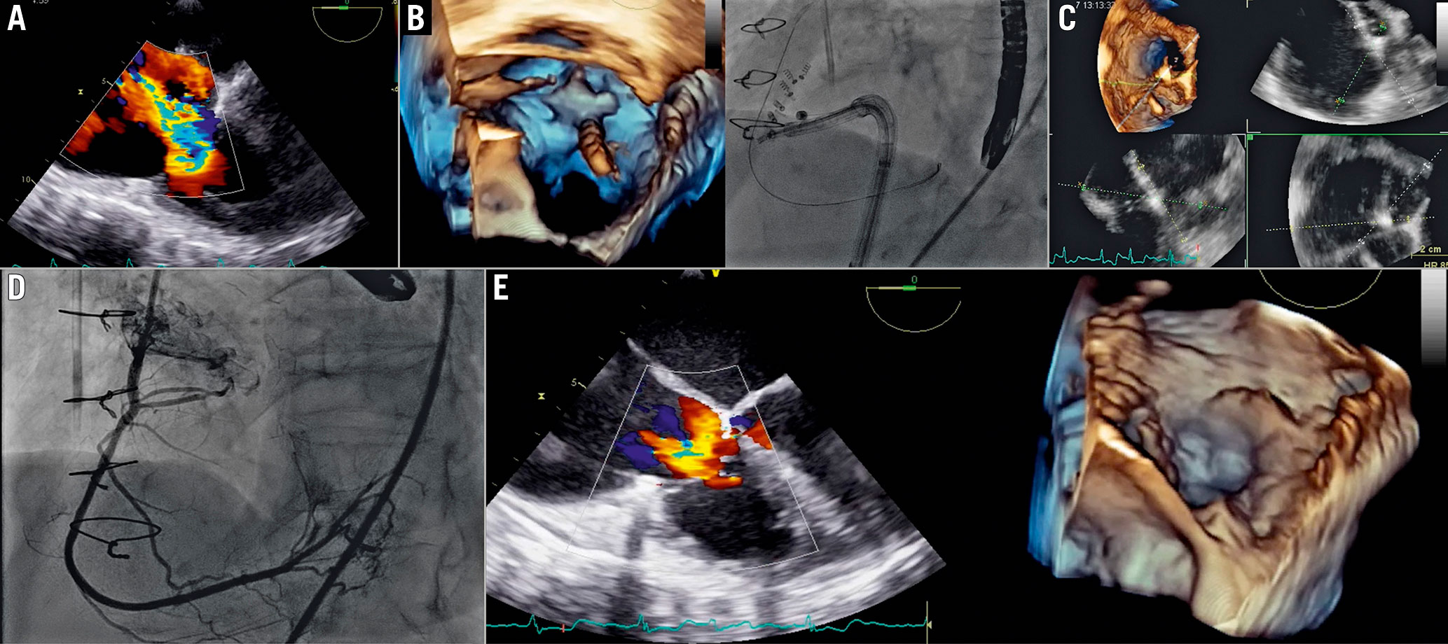
Figure 13. Cardioband procedure in the tricuspid valve. A) Baseline evaluation. B) Navigation of delivery system along the tricuspid annulus. C) 3D MPR for fine evaluation of the delivery catheter on the annulus. D) Right coronary angiography to assess injury of the RCA during anchor implantation. E) Final result.MPR: multiplanar reconstruction; RCA: right coronary artery
Leafletapproach
The rationale behind TV leaflet approximation (TriClip[Abbott Laboratories] and PASCAL systems) is to restore coaptation between leaflets and reduce the regurgitant orifice area. The procedural steps and imaging guidance are shown in Figure 14-Figure16 and Supplementary Table 9.
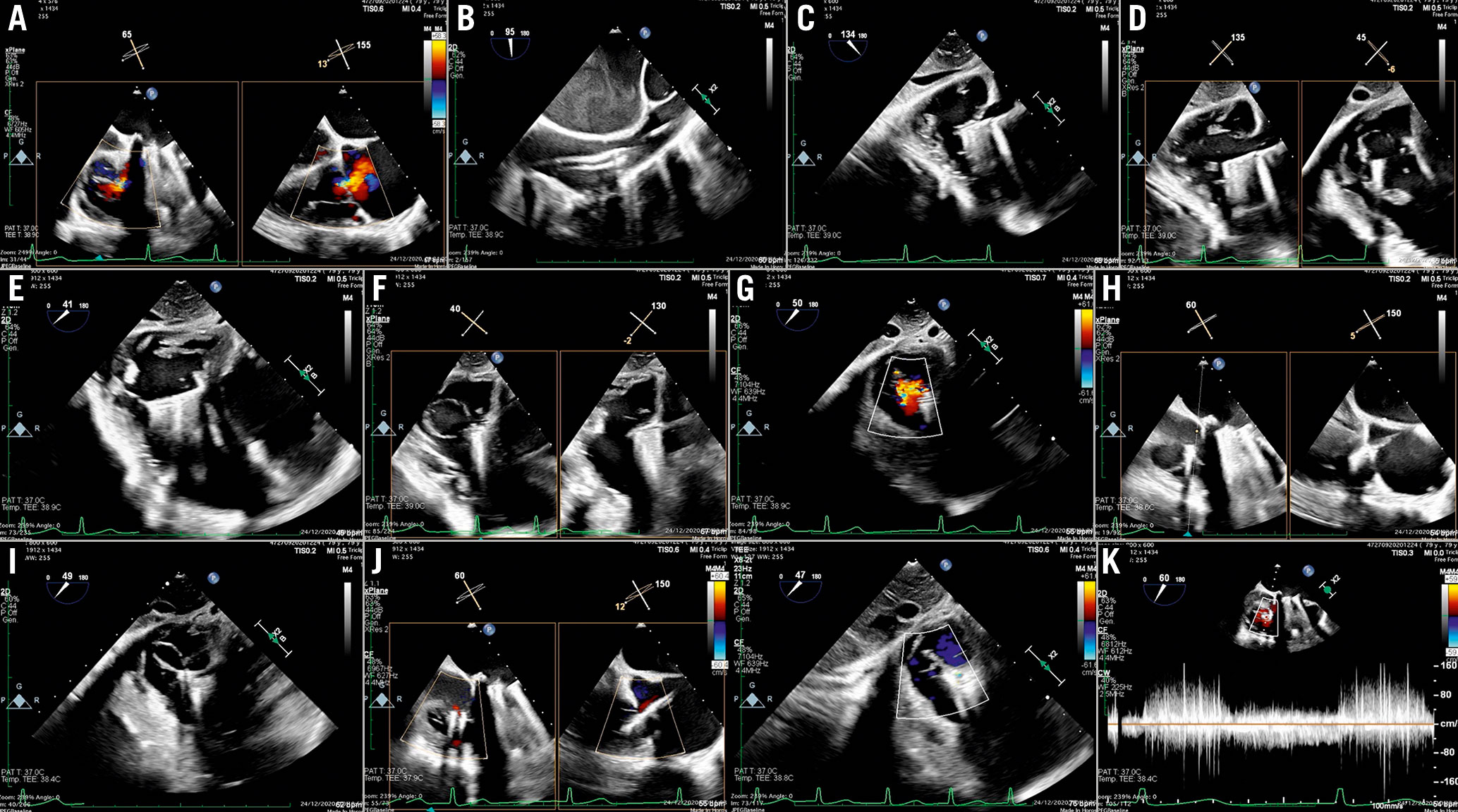
Figure 14. TriClip procedure. A) Baseline evaluation. B) GC insertion into the RA. C) Steering manoeuvre towards the TV plane and trajectory (LAX transgastric view). D) CDS advancement into the RV (biplane transgastric views). E) Clip arm orientation (SAX transgastric view). F) Leaflet grasping. G) Residual TR after first clip implantation (SAX transgastric view). H) Assessment of leaflets insertion. I) Second clip implantation. J) Result after second clip. K) Transvalvular gradient.CDS: clip delivery system; GC: guide catheter; RA: right atrium; RV: right ventricle; SAX: short axis; TR: tricuspid regurgitation
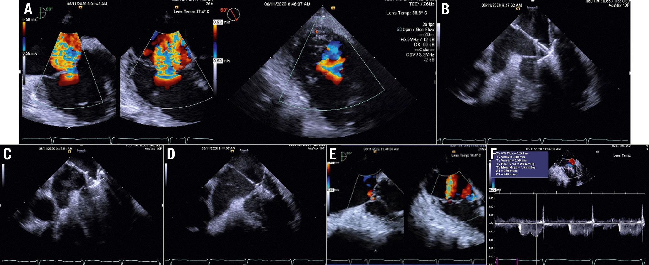
Figure 15. TriClip procedure guided by ICE. A) Baseline evaluation. B) Clip advancement into the RV. C) Leaflet grasping. D) Assessment of leafletinsertion. E) Final result. F) Transvalvular gradient. Courtesy of Mani Vannan, Marcus Heart Valve Center, Piedmont Heart Institute, Atlanta, USA. MV: mitral valve
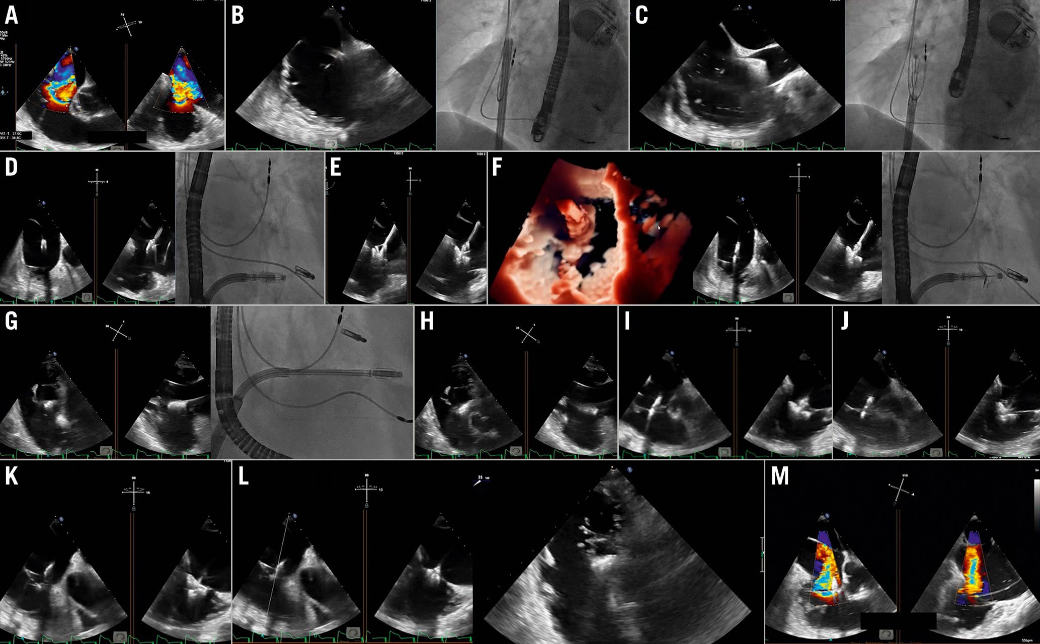
Figure 16. Tricuspid PASCAL procedure. A) Baseline evaluation. B) Guide sheath placement inside the RA. C) Implant system insertion. D) Trajectory. E) Clasp check. F) Implant orientation. G) Valve crossing. H) Confirmation of implant orientation. I) Implant retraction. J) Leaflet clasping. K) & L) Assessment of leaflet insertion. M) Result evaluation after implant release. Courtesy of Dr Ralph Stephan Von Bardeleben, Department of Cardiology I, Heart Valve Center, Universitätsmedizin Mainz, Mainz, Germany.RA: right atrium
Assessing the results using echocardiography can be challenging, especially when multiple TR jets are created47. Theoretically, only the proximal isovelocity surface area (PISA) method, the volumetric methods and the 3D vena contracta area are appropriate for the quantitative evaluation of multiple regurgitant orifice by summation. Additionally, useful findings are the presence of changes of the hepatic vein flow patterns.
CT-fluoroscopy fusion imaging is another useful tool for assessment of eligibility for tricuspid transcatheter interventions and it can also serve as a guide to determine the optimal site. It provides an interesting tool for procedural planning and guidance39.
Patent foramen ovale and atrial septal defect closure
PFO is a common finding affecting approximately 25% of the general population48. In some patients it may, however, have a pathophysiologic role in causing cryptogenic stroke, migraine or hypoxaemia due to right-to-left shunting4950515253.
Correct identification and description of a right-to-left shunt across a PFO is mandatory before percutaneous closure is attempted. Contrast-enhanced transcranial Doppler (TCD) or contrast-enhanced TTE are common first-line examinations that carry a sensitivity of 94% and 88%, respectively, and a specificity of 92% and 82%, respectively54.
According to a recent European position paper on PFO closure, contrast-enhanced TCD should be performed in case of a negative or equivocal contrast TTE55. If a right-to-left shunt is confirmed, a contrast-enhanced TOE should be performed in order to confirm the exact location of the shunt and PFO anatomy.
An ostium secundum represents the only type of ASD that can be closed percutaneously in the majority of cases. Anecdotal cases of percutaneous closure of other ASD types have been reported56. Percutaneous closure of an ASD is considered the first-choice treatment for ostium secundum ASD57. Exclusion criteria for percutaneous treatment are5458: 1) stretched defect diameter greater than 38 mm; 2) partial anomalous venous connection requiring surgical repair; and 3) absence or partial deficit (<5 mm) of rims with the exception of the aortic one.
Procedural steps and imaging guidance
Percutaneous PFO closure usually involves a double disc device or a suture-mediated device and can be performed using fluoroscopy only. However, echographic guidance is recommended to monitor the procedure in order to increase its safety, efficacy and to assess the final result. On fluoroscopy, the procedure is normally followed in a shallow LAO cranial projection.
When a double disc device is used, the procedure steps are the same for both PFO and ASD closure as follows (Figure 17, Supplementary Table 10): 1) right venous femoral access; 2) crossing of the PFO/ASD with a multipurpose catheter; 3) positioning of the device delivery sheath across the IAS on a stiff wire (directed in the left upper pulmonary vein); 4) sequential opening of the left and the right atrial discs of the device. The correct position of the device is finally assessed. The aim is to check the two discs lying parallel to each other between the IAS, to systematically review the rims and edges of the device, to rule out interference with other structures. Moreover, colour-Doppler allows evaluation of the possible persistence of a left-to-right shunt at the edges of the device or within it, and finally, 5) stability manoeuvre and the final release.
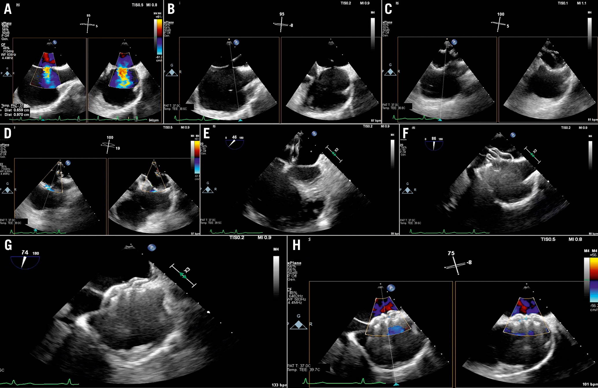
Figure 17. ASD closure procedure. A) Baseline evaluation and sizing of the defect. B) ASD crossing. C) & D) Balloon sizing. E) Left disc opening. F) Right disc opening and push-and-pull test. G) Device release. H) Colour-Doppler shows absence of residual shunt.ASD: atrial septal defect
In case of ASD closure, a sizing balloon is required. The balloon is inflated with the contrast medium until ASD occlusion (no shunt at colour-Doppler). ASD balloon-stretched diameters can be obtained on a simultaneous 2D biplane view. These correspond to the balloon waist that can be observed and measured either with echocardiography or fluoroscopy. Once sizing of the defect is performed, the size of the device is chosen with an oversizing of about 30%.
Baseline and final contrast studiesto assess the closure of the PFO arerecommended.
When a suture-mediated device is used, a first suture is deployed on the septum secundum, then a suture on the septum primum, and finally the sutures are tightened together by deploying a small plastic knot and a final angiogram is performed. The C-arm is positioned in a steep LAO (60°) projection and the X-ray tube should not be moved throughout the procedure, hence a vertebral body marks the exact position of the septum primum and secundum, the target of the sutures. During the procedure, TOE might follow the passage of the wires and of the catheters, monitor complications and the final result; however, the sutures and their deployment needles are not visible on echocardiography.
ICE is an excellent tool for intraprocedural guidance during percutaneous PFO closure.
The ICE catheter is introduced transfemorally in the right atrium. If a catheter with a linear probe is used, the transducerneeds to be oriented towards the interatrial septum (by turning the catheter under fluoroscopic guidance).
Bidimensional imaging will visualise the IAS and its anatomical characteristics. By injecting ultrasonic contrast medium in the femoral or peripheral vein, the degree and characteristics of the right-to-left shunt can be assessed. Colour-Doppler imaging can confirm additional left-to-right shunts and assess the colour flow across the PFO. In case of balloon interrogation of the PFO, the sizing balloon can be easily visualised by ICE. In case of double-discdevices, the ICE in the long axis atrial septal view is able to visualise all the steps of the procedure with the left atrial disc opening, its approximation towards the IAS and the right disc opening. The device can be assessed in two planes before the final release and colour Doppler can assess potential residual shunts (Figure 18).
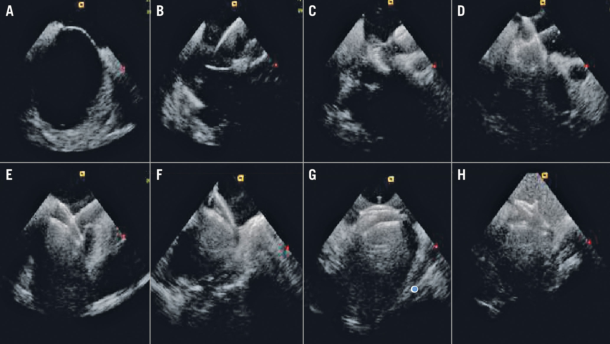
Figure 18. ICE guidance of a double disc device PFO closure. A) Long-axis atrial septal view at baseline. B) Left atrial disc opening. C) Approximation towards the IAS. D) The right disc opening. The device can be assessed in two planes (E & F) before the final release. After the final release (G), the bubble test should be repeated in order to assess the immediate result (H).IAS: interatrial septum; ICE: intracardiac echocardiography PFO: patent foramen ovale
Follow-up
TTE provides adequate images of the occluder device using the apical four-chamber view and subxiphoid acoustic windows. The degree of residual shunt can be easily quantified by the echographic contrast medium injection.
Percutaneous closure of paravalvular leaks
PVL is a complication after surgical or transcatheter valve replacement. About 1-5% of PVLs can lead to serious consequences, including congestive heart failure and haemolytic anaemia. Traditionally, surgical re-intervention has been considered the treatment of choice for symptomatic patients with PVLs. However, it is associated with a high risk of morbidity and mortality, and the percutaneous option has emerged as a less invasive alternative.
Indications for PVL closure
In general, there are two indications for the closure of a PVL59:
1. Patients with significant regurgitation due to the PVL and symptoms of congestive heart failure.
2. Patients with significant regurgitation due to the PVL and haemolysis.
Important contraindications to PVL closure include presence of active local or systemic infection, active ischaemia, mechanical instability of the prosthetic valve, intracardiac thrombus, and patients with a life expectancy due to comorbidities that is less than six months.
Preprocedural evaluation and preprocedural planning
TOE, particularly 3D TOE, is the imaging modality of choice in percutaneous PVL closure60. It plays an essential role in evaluating the defect, guiding the procedure, monitoring complications and assessing the results. Specifically, mitral PVL closure is a highly echo-dependent intervention.
An exhaustive evaluation of PVL anatomy is essential for the success of the procedure. Real-time 3D TOE imaging is especially useful to this end, particularly in mitral PVL. However, paravalvular defects should be confirmed with colour Doppler to avoid confusion with areas of echo drop-out due to low spatial resolution (Figure 19).
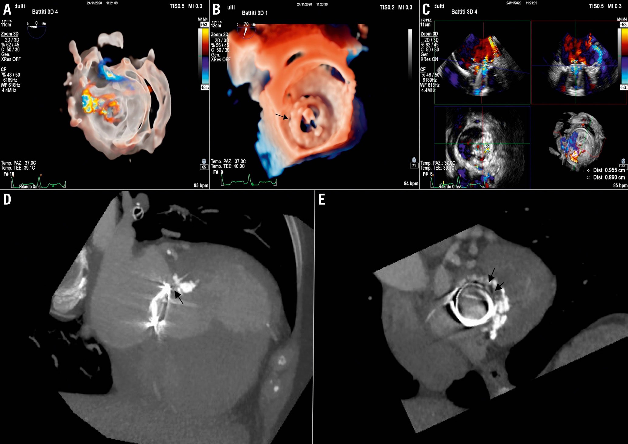
Figure 19. Leak evaluation and preprocedural planning. A & B) Localisation of mitral PVL. A) 3D colour-Doppler (transparency rendering). B) En face view of mitral valve prosthesis (3D true view rendering). C) Leak sizing by 3D MPR. D & E) Computed tomography (CT). D) Coronal view. E) Axial view of the prosthesis. CT evaluation is helpful particularly for sizing of the PVL and for deriving the working fluoroscopic projection.MPR: multiplanar reconstruction; PVL: paravalvular leak
Furthermore, during preprocedural TOE, it is important to evaluate the presence of pericardial effusion and intracardiac thrombus and the transprosthetic gradient. In the presence of intracardiac thrombus, the procedure must be postponed. Pulmonary vein inflow for mitral leaks or descending aorta flow for aortic leaks should also be documented. Finally, the relation with adjoining structures (coronary arteries, calcium…) should be examined.
The shape of the cross-sectional area of the vena contracta (oval, irregular…), the vena contracta diameters, and the channel length determine the choice and size of occluding devices. Moreover, a surgical suture crossing the defect can impact on the choice of the devices and should be evaluated.
CT can provide additive information. Cardiac CT angiography can easily define location, size, shape, and trajectory of a PVL by MPR. Moreover, CT analysis allows preprocedural determination of the optimal fluoroscopic plane to be used during the procedure.
TOE guidance for PVL closure
The procedure is performed under fluoroscopic and TOE guidance (Figure 20A-Figure 20D, Supplementary Table 11).
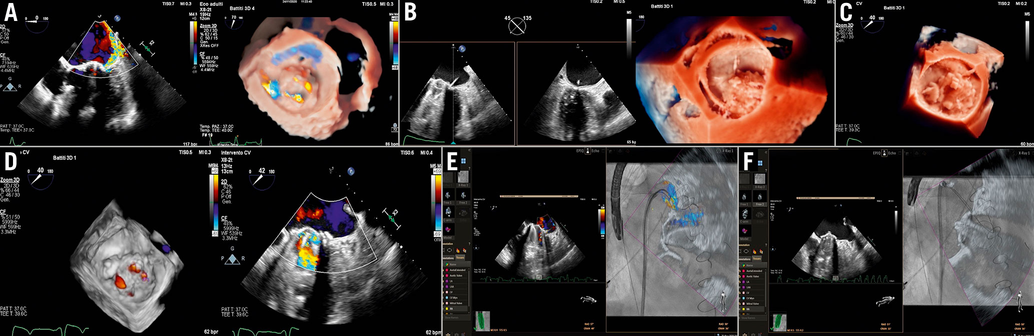
Figure 20. Mitral PVL closure procedure. A) Baseline evaluation. B) PVL crossing by hydrophilic guidewire. C) PVL crossing by hydrophilic guidewire. C) Device deployment. D) Final result. E& F) Fusion imaging. E) Colour-Doppler superimposed to fluoroscopy. The colour jet is used as a marker. F) 2D imaging superimposed to fluoroscopy showing the PVL crossing.PVL: paravalvular leak
During the procedure, only a target-oriented TOE is performed to confirm size, shape and location of the leak. TOE is used to guide the TSP, to help the crossing of the guidewire and catheter through the defect, to ensure an adequate positioning of the device over the defect, to evaluate prosthetic valve function, and to identify complications. To evaluate the results, the absence or reduction of colour-Doppler flow is the first and simplest sign of success. The 3D cross-sectional area of the vena contracta before and after the procedure can be compared, as well as prosthesis gradient and pulmonary vein (mitral leak) or descending aorta flow (aortic leak) in similar haemodynamic conditions.
In some patients with aortic PVL and contraindications to TOE, a procedure monitored solely by TTE could be carried out, but a previous CT is mandatory in this case.
Echo-fluoroscopic fusion imaging has simplified the percutaneous procedures of transcatheter PVL closure, particularly in cases of radiolucent prosthetic valves61. By superimposing 2D, colour Doppler and 3D modalities on fluoroscopy, the fusion may help to (Figure 20E, Figure 20F):
–Carry out the TSP
–Identify the site of the leak on the fluoroscopic projection
–Engage the leak
–Deploy the device
–Evaluate the interference with prosthesis
Risk of radiation exposure
The interventional imager can be subjected to high levels of radiation exposure due to their proximity to the X-ray source. Thus, a number of simple measures, such as the use of a protective lead coat, portable lead shielding, radiation reducing gloves, and distancing from the X-ray source, must be taken to minimise exposure and the associated risks62. In addition, the imager should be monitored for radiation doses during procedures and a record of the cumulative dose maintained. Using a remote controlled robotic arm for real-time echocardiographic monitoring during procedures could be a future solution.
Grey areas and future directions
Despite an increased demand for physicians with specific technical skills and competencies in SHD imaging, there is no standardised core curriculum for SHD interventional imagers so far62.
The presence of metallic artefacts, as well as occasional difficulties in discerning tissue from devices/catheters, still represent a challenge for the imager. The development of specific tools, able to identify the different components by different colour codes, could facilitate the work of the team.
Accurate evaluation of the procedural result after device implantation is another open challenge. The presence of multiple jets, eccentricity, etc., make the use of the standard quantification methods unreliable. Thus, new software enabling semi-automated 3D flow quantification could be more accurate than conventional methods63.
Conclusions
Imaging plays a central role for clinical decision making in SHD: before the procedure, to decide appropriateness and feasibility, as well as for intraprocedural guidance and post-procedural follow-up. The continuous expansion of device availability benefits from the improvements in the field of imaging. Consequently, interventional imaging as a subspecialty is likely to become more and more important with the development of a newer type of specialist, the “SHD Interventional Imager”.
Conflict of interest statement
The authors have no conflicts of interest to declare.
Supplementary data
To read the full content of this article, please download the PDF.