Abstract
Interventional cardiologists have traditionally relied upon fluoroscopic imaging for percutaneous coronary interventions. Transcatheter structural heart interventions, however, require additional imaging modalities such as echocardiography and multislice computed tomography (MSCT) for pre-, intra- and post-procedural assistance. MSCT has emerged as the critical imaging modality for patient and device selection prior to transcatheter structural heart interventions. MSCT is unique as it provides a complete 3-dimensional (3D) dataset of the heart and vasculature that is amenable to multiplanar reconstruction for 2-dimensional (2D) or volume-rendered interpretations. Herein, we present a modality-independent terminology for understanding volumetric images in the context of transcatheter heart valve therapies. The goal of this system is to allow physicians to readily interpret the orientation of fluoroscopic, MSCT, echocardiographic and MRI images, thus generalising their understanding of cardiac anatomy to all imaging modalities.
Introduction
Interventional cardiologists have traditionally relied upon fluoroscopic imaging for percutaneous coronary interventions. Transcatheter structural heart interventions, however, require additional imaging modalities such as echocardiography and multislice computed tomography (MSCT) for pre-, intra- and post-procedural assistance. Unlike cardiac surgeons who have direct visualisation of structures during valve repair or replacement, physicians performing transcatheter heart valve interventions are entirely dependent on multimodal cardiac imaging for valve size selection and positioning; imaging becomes the “eyes of the Heart Team”.
X-ray fluoroscopy provides excellent resolution and tracking of cardiac devices, but is limited by the requirement for contrast enhancement to visualise anatomical structures. Understanding fluoroscopic cardiac anatomy can, however, facilitate optimal positioning and deployment of prostheses during transcatheter valve repair/replacement, left atrial appendage occlusion, septal defect closure, paravalvular leak closure, etc. To date, these therapies have been performed using standardised fluoroscopic viewing angulations that do not account for the considerable variation in anatomy between patients. Two-dimensional fluoroscopy creates foreshortening and overlap of discrete cardiac structures and consequently the use of suboptimal fluoroscopic projections can yield suboptimal procedural outcomes.
Patient-specific fluoroscopic viewing angles in contrast have been shown to improve procedural safety and efficacy1-9. While widely used in the realm of transcatheter aortic valve implantation, the imminent introduction of transcatheter mitral and tricuspid valve interventions will further challenge physicians’ understanding of the optimal fluoroscopic views of valve leaflets and their segments, papillary muscles and surrounding structures (e.g., the left ventricular outflow tract, the left atrial appendage).
Echocardiographic guidance of transcatheter structural heart interventions has now become routine in clinical practice. Echocardiography is cheap, widely available, and most cardiac centres boast recognised echocardiographic experts. The technique offers high temporal resolution of cardiac structures, and 3D echocardiography is providing operators with new perspectives about the relative position of cardiac structures and devices. The poor echogenicity of most cardiac devices, however, and the limited field of view inhibit the exclusive use of 3D echocardiography for structural heart interventions. Furthermore, the interventional cardiologist may not be familiar with standardised echocardiographic viewing planes and their relevance to an advancing delivery catheter.
More recently, MSCT has emerged as the critical imaging modality for patient and device selection prior to transcatheter structural heart interventions10. MSCT is unique as it provides a complete 3D dataset of the heart and vasculature that is amenable to multiplanar reconstruction for 2D or volume-rendered interpretations; it is perhaps the “next best thing” to having a human heart specimen for anatomic study. With the introduction of transcatheter aortic valve replacement, interventional cardiologists have become aware of the value of MSCT to provide preprocedural, patient-specific information that can significantly impact device selection, procedural performance and fluoroscopic viewing angles for optimal device deployment10-13.
Herein, we present a modality-independent terminology for understanding volumetric images in the context of transcatheter heart valve therapies. The goal of this system is to allow physicians to readily interpret the orientation of fluoroscopic, MSCT, echocardiographic and MRI images, thus generalising their understanding of cardiac anatomy to all imaging modalities.
Heart valve anatomy: perspectives from the echocardiographic 3-chamber, 2-chamber and short-axis views
Traditionally, heart valve anatomy has been described in a relatively fragmented, disconnected fashion, without consideration of the functional unit as a whole. Moreover, while the multimodal imaging of these anatomical and functional components has been described in detail, little consideration has been given to understanding their configuration in a modality-agnostic manner. For example, for the mitral valve, the anterior and posterior mitral annulus, chordae tendineae and papillary muscles are described in exquisite detail with respect to their composition, relative proportions, and location14. Knowledge of this kind is of course important, but is perhaps less practical for translating anatomical information between various imaging modalities for patient and device selection, and for procedural guidance.
Understanding heart valve anatomy according to the chambers of the heart may facilitate the translation of anatomical information from one imaging modality to another, and allow Heart Team members to speak a common language. The concept of heart chamber anatomy has its roots in echocardiography, but chamber anatomy can also be applied to fluoroscopy and MSCT. In essence, a common understanding of chamber anatomy would allow each Heart Team member to understand and discuss which structures can be appreciated in a particular chamber view (e.g., 2-chamber, 3-chamber, en face view) across the spectrum of imaging modalities.
To better understand heart valve anatomy according to chamber views, it is best to begin with MSCT and describe the anatomical structures according to their attitudinally correct position. This nomenclature implies that the subject is facing the observer and standing upright. Thus, structures closer to the observer are described as being anterior and those relatively farther away are posterior. Components lying closer to the head are superior (cranial [CRA]) and those towards the feet are said to be inferior (caudal [CAU]). Structures to the left-hand side of the observer are right-sided and those to the observer’s right are left-sided. Discussing heart structures in their attitudinal position is in perfect agreement with nomenclature used for CT and X-ray fluoroscopic imaging, which is not necessarily the case with echocardiography. The fluoroscopic screen portrays the thorax in an upright orientation despite the patient being in a supine position. Superior and inferior structures are appreciated in the upper and lower halves of the screen. The direction of fluoroscopic projections is described based on two conventional angles, CRA/CAU and left anterior oblique (LAO)/right anterior oblique (RAO). In the anteroposterior (AP) viewing angle (CRA/CAU 0, LAO/RAO 0), right- and left-sided structures are found on the left and right sides of the screen, respectively. Fluoroscopy and MSCT share a common image contrast mechanism: X-ray attenuation. Consequently, it is possible to readily use MSCT volumetric data to simulate fluoroscopic images. Measurement of fluoroscopic angulation from MSCT data can be done with software packages that offer double-oblique multiplanar reconstruction; the exact CRA/CAU and RAO/LAO angulations for a particular structure can be obtained by analysing the oblique sagittal and oblique transverse views, respectively.
To demonstrate the concept of “chamber view heart anatomy” we will focus on the mitral valve and surrounding structures (atrial septum, pulmonary veins, left atrial appendage, mitral annulus, mitral valve leaflets and their segments, and the papillary muscles). An MSCT scan of a 66-year-old male patient with severe mitral regurgitation is analysed using the software package FluoroCT 3.1 (Montreal, QC, Canada). It is worth reiterating that a particular chamber view for a specific patient can be replicated across modalities including echocardiography, MSCT, fluoroscopy and magnetic resonance imaging.
Chamber view heart anatomy: from MSCT to fluoroscopy to echocardiography
The mitral valve annulus optimal projection curve, or the mitral annulus S-curve, describes fluoroscopic LAO/RAO angles for any given CRA/CAU angles where the mitral annulus is visualised in plane. The optimal projection curve is obtained by MSCT multiplanar reconstructions of the mitral valve. The vast majority of patients have similar appearing optimal projection curves; variable 3D orientations of mitral annuli across patients will result in some differences in these curves. Nonetheless, planar views of the mitral valve can be obtained in steep RAO/CAU, shallow RAO/CRA, and steep LAO/CRA views, while the en face view of the mitral valve annulus is appreciated in an LAO/CAU projection. Further analyses of these views demonstrate that a steep RAO/CAU or steep LAO/CRA projection corresponds to a 3-chamber view of the heart, a shallow RAO/CRA projection corresponds to a 2-chamber view of the heart, and an LAO/CAU projection corresponds to a short-axis view of the heart. For completeness, steep RAO/CRA views (typical en face views of the aortic annulus) provide a short-axis view of the heart. Optimal projection curves (S-curves) can also be obtained for the aortic valve, atrial septum and left atrial appendage ostium (Figure 1).
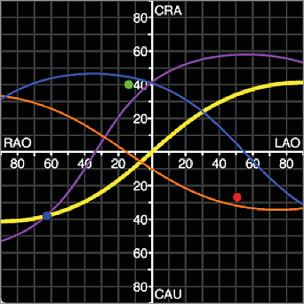
Figure 1. Optimal projection curves (S-curves) of the mitral valve annulus (purple), aortic valve annulus (yellow), atrial septum (blue), and left atrial appendage ostium (orange) from a 66-year-old male patient with severe mitral regurgitation. Any intersection between two curves will provide a fluoroscopic viewing angle where both structures are in plane.
Although fluoroscopic angulations are dependent on the specific orientation of the heart within the thorax, a parameter that may vary considerably between patients, general guidelines can be stated (Figure 1):
– 3-chamber view: steep RAO/CAU or steep LAO/CRA projections
– 2-chamber view: shallow RAO/CRA projections
– Short-axis view: an LAO/CAU or steep RAO/CRA projections
Fluoroscopic 3-chamber view
The fluoroscopic 3-chamber view of the left heart can be obtained in a steep RAO/CAU view; the mirror image is obtained in a steep LAO/CRA view. The corresponding 3-chamber view on transthoracic echocardiography can be appreciated from a parasternal long-axis view, and on transoesophageal echocardiography from a mid-oesophageal long-axis 120-140-degree or transgastric long-axis 110-130-degree view. Figure 2 provides several short-axis heart segments that help better understand the generation of the 3-chamber view (see yellow-tipped triangle). Figure 3 describes general fluoroscopic characteristics of the 3-chamber view. From these generalisations, it can be realised that aortic annulus measurements obtained in a parasternal long-axis 3-chamber view provide a minor axis measurement and can lead to significant underestimation of the true annular dimensions. Furthermore, the fluoroscopic 3-chamber view (RAO/CAU) is excellent for wire manipulations across the mitral valve into the left atrium from a transapical approach by allowing separation of the LVOT/aortic annulus from the mitral valve; not uncommonly, the guidewire is advanced across the aortic valve. As will be shown in the 2-chamber view, the aortic and mitral valves are superimposed, which can make it difficult to orient the wire in the intended direction by fluoroscopy alone. The 3-chamber view is also useful when directing catheters towards the anterior or posterior mitral valve leaflets, but not if segments (e.g., A1/P1) of the mitral valve need to be targeted. For transseptal punctures, a fluoroscopic 3-chamber view has the atrial septum en face and therefore the transseptal needle is pointing “into the screen”.
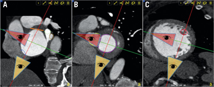
Figure 2. The points of view from the red (oblique coronal) and yellow (oblique sagittal) triangles provide the 2-chamber and 3-chamber views, respectively. A) Short-axis view at the level of the atrial septum (blue) and left atrial appendage (orange). The yellow triangle point of view (3-chamber, steep RAO/CAU) appreciates the en face view of the atrial septum and left atrial appendage while the red triangle point of view (2-chamber, shallow RAO/CRA) appreciates the atrial septum and ostium of the left atrial appendage in plane. B) Short-axis view at the level of the aortic valve (yellow) and mitral valve (purple). Note that the yellow triangle point of view (3-chamber, steep RAO/CAU) sees the minor axis of both the mitral and aortic valve annuli while the red triangle point of view (2-chamber, shallow RAO/CRA) sees the major axis of both the mitral and aortic valve annuli. From the yellow triangle perspective, the anterior and posterior mitral valve leaflets are separated but the segments of the leaflets (A1, A2, A3) (P1, P2, P3) are overlapping; from the red triangle perspective the anterior and posterior mitral valve leaflets are overlapping but the A1/P1, A2/P2, and A3/P3 segments can be distinguished. C) Short-axis view at the level of the papillary muscles. From the yellow triangle point of view (3-chamber, steep RAO/CAU), the papillary muscles can be seen overlapping while from the red triangle point of view (2-chamber, shallow RAO/CRA) the papillary muscles are maximally separated.
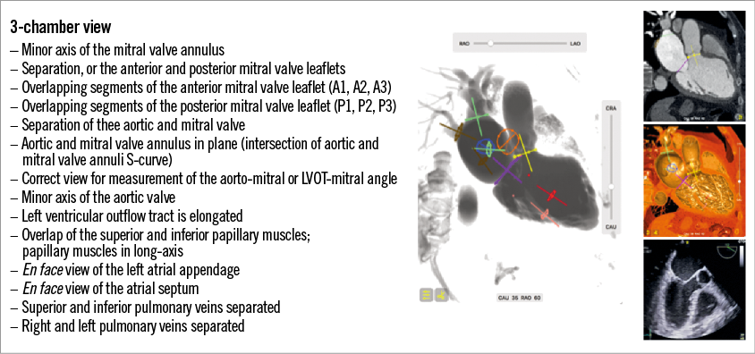
Figure 3. 3-chamber view of the left heart. The large central image represents the 3-chamber fluoroscopic view in RAO 60 CAU 35 for this particular patient. Mitral annulus: purple; aortic annulus: yellow, pink and red: inferior and superior papillary muscles, respectively; blue: atrial septum; orange: left atrial appendage; green: left superior and inferior pulmonary veins; brown: right superior and inferior pulmonary veins. The right panel of pictures from top to bottom represent corresponding 2D MSCT 3-chamber view, 3D endovascular MSCT 3-chamber view and transoesophageal echocardiography 3-chamber view.
The 2-chamber view
The fluoroscopic 2-chamber view of the left heart can be obtained in a shallow RAO/CRA view. The corresponding view on transthoracic echocardiography can be appreciated from the apical 2-chamber view and on transoesophageal echocardiography from a mid-oesophageal 90-degree or transgastric long-axis 90-degree view. Figure 2 provides short-axis views that help better understand the generation of the 2-chamber view (see red-tipped triangle). Figure 4 describes general fluoroscopic characteristics of the 2-chamber view; in many respects they contrast those of the 3-chamber view.
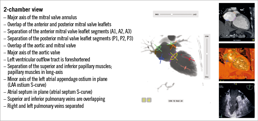
Figure 4. 2-chamber view of the left heart. The large central image represents the 2-chamber fluoroscopic view in RAO 24 CRA 13 for this particular patient. Mitral annulus: purple; aortic annulus: yellow, pink and red: inferior and superior papillary muscles, respectively; blue: atrial septum; orange: left atrial appendage; green: left superior and inferior pulmonary veins; brown: right superior and inferior pulmonary veins. The right panel of pictures from top to bottom represent corresponding 2D MSCT 2-chamber view, 3D endovascular MSCT 2-chamber view and transoesophageal echocardiography 2-chamber view.
The 2-chamber view (which can be close to an AP view in some patients) provides the major axes of the aortic and mitral valve. Historically, before the advent of MSCT for transaortic valve replacement sizing, an aortogram in a “quasi-AP” view would sometimes suggest a larger transcatheter aortic valve than the 3-chamber echocardiography measurements. The 2-chamber view is useful to direct catheters towards segments of the mitral valve (e.g., A1/P1 vs. A3/P3), but not for advancing catheters towards the anterior or posterior mitral valve leaflets. The papillary muscles are also maximally separated in a superior and inferior attitudinal location, and may provide important information for those devices that need to interact or avoid these structures. For transseptal punctures, the fluoroscopic 2-chamber view can appreciate the atrial septum in plane and therefore the transseptal needle would be elongated and pointing from left to right of the screen.
The short-axis view of the left heart
The fluoroscopic short-axis view of the left ventricle and, consequently, the mitral valve, can be obtained in an LAO/CAU projection. The corresponding view on transthoracic echocardiography can be appreciated from the parasternal and subcostal short axes and on transoesophageal echocardiography from a transgastric short-axis 0-degree view. Figure 5 describes general fluoroscopic characteristics of the short-axis view of the left ventricle (i.e., en face view of the mitral valve). The short-axis view, in combination with either the 2-chamber or 3-chamber views, can help advance catheters towards the anterior or posterior leaflet as well as their respective segments. Interestingly, in the short-axis view, the major axis of the left atrial appendage ostium can be visualised in plane, while the 2-chamber view can provide the minor axis of the ostium in plane using the optimal projection (S) curve. The 3-chamber view typically finds the en face view of the left atrial appendage.
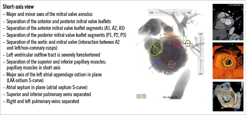
Figure 5. Short-axis view of the left heart. The large central image represents the short-axis fluoroscopic view in LAO 56 CAU 25 for this particular patient. Mitral annulus: purple; aortic annulus: yellow; pink and red: inferior and superior papillary muscles, respectively; blue: atrial septum; orange: left atrial appendage; green: left superior and inferior pulmonary veins; brown: right superior and inferior pulmonary veins. The right panel of pictures from top to bottom represents corresponding 2D MSCT short-axis view, 3D endovascular MSCT short-axis view and 3D transoesophageal echocardiography short-axis view at the level of the mitral annulus from a left atrial view.
Conclusion/perspective
The majority of interventional cardiologists have not received formal training in echocardiography or MSCT for the purposes of transcatheter structural heart interventions. The relationship between imaging modalities and their relative merits for optimising success are poorly understood. As described herein, an in-depth understanding of MSCT can provide a platform to grasp the nuances of fluoroscopic and echocardiography anatomy. With this knowledge, the concepts of fusion imaging may be better understood.
Dedicated imaging courses play a vital role in filling this “educational gap” and bringing together the knowledge and cross-fertilisation of the non-invasive and invasive imaging specialist. Invasive cardiology fellows interested in pursuing careers in transcatheter structural heart interventions are encouraged to obtain specific training in echocardiography and MSCT. Likewise, cardiac imaging fellows interested in pursuing careers in transcatheter structural heart interventions are encouraged to attend the cardiac catheterisation lab and become familiar with these procedures.
Conflict of interest statement
N. Piazza is a consultant/proctor for Medtronic and Microport, is a consultant and has equity shares in HighLife, and is a cofounder of FluoroCT. D. Mylotte is a consultant/proctor for Medtronic and Microport. P. Theriault Lauzier is a cofounder of FluoroCT.