Abstract
Performing transcatheter valve interventions requires a thorough knowledge of right heart imaging. Integration of chamber views across the spectrum of imaging modalities (i.e., multislice computed tomography, fluoroscopy, and echocardiography) can facilitate complex transcatheter interventions. Optimal fluoroscopic viewing angles for guiding interventional procedures can be obtained using preprocedural multislice computed tomography scans. The present manuscript describes the fluoroscopic viewing angles necessary, when using multislice computed tomography, to appreciate heart chamber anatomy and their relationship to echocardiography.
Abbreviations
Ao: aortic valve
CAU: caudal
CRA: cranial
MSCT: multislice computed tomography
MV : mitral valve
TAVR: transcatheter aortic valve replacement
TOE: transoesophageal echocardiography
TV: tricuspid valve
TTE: transthoracic echocardiography
Introduction
The patient selection and procedural planning for transcatheter structural interventions have been facilitated by the extensive use of multislice computed tomography (MSCT) multiplanar reconstruction1,2. This imaging technique allows the identification of the optimal fluoroscopic viewing angles of left- and right-sided heart structures, in particular the aortic, mitral and tricuspid valve complexes3,4. The use of standardised fluoroscopic viewing angles, during interventions targeting the left and right heart valvular apparatus, can be extremely helpful in technically challenging scenarios (e.g., mitral and tricuspid valve interventions). A better understanding of multimodality imaging of heart chamber anatomy can reduce the procedural time, radiation dose, contrast volume, and complications during transcatheter valve interventions while providing guidance for the operators.
This paper aims to summarise and describe the anatomy of left- and right-sided heart valvular complexes by integrating MSCT, fluoroscopy and echocardiography.
Attitudinal description of the anatomy of the heart
In this review, cardiac structures will be described according to their attitudinal orientation, as detailed in a previous publication by Thériault-Lauzier et al3. This approach allows building a consistent nomenclature for both fluoroscopic and MSCT imaging of the heart. As a consequence, with the subject facing the observer and standing upright, structures closer to the observer are described as anterior and those relatively farther away as posterior. Components lying closer to the head are superior (i.e., cranial [CRA]) and those towards the feet are said to be inferior (i.e., caudal [CAU]). Structures on the right-hand side of the subject are right-sided, and vice-versa for the left. While describing heart structures in their attitudinal position allows a common nomenclature between fluoroscopy and MSCT, conventional echocardiographic nomenclature tends to label structures according to their relative position within the heart (e.g., septal, lateral) and may require some adjustments.
MSCT and fluoroscopic anatomy of the heart
As a consequence of its two-dimensional (2D) nature, fluoroscopy is affected by parallax, which requires the operator to select multiple viewing angles to achieve accurate and exhaustive three-dimensional (3D) spatial information. In contrast, MSCT is a 3D volume acquisition technique and therefore is not affected by parallax, with the preservation of the spatial resolution in all imaging planes. For any particular structure, an optimal fluoroscopic viewing angle can be calculated to achieve minimal errors in device positioning due to parallax. In this fluoroscopic projection the source-to-detector direction is orthogonal to the axis of symmetry of the anatomical feature of interest. The direction of structures can be achieved by an accurate analysis of the MSCT images with the creation of an optimal projection curve (i.e., S-curve)5,6. Based on this optimal projection curve, it is possible to select an optimal fluoroscopic angle for a given anatomical structure of interest. In addressing structural procedures, different cardiac structures must be distinguished for the accurate implant of specific devices by using specific fluoroscopic angulations which provide the maximal separation between such structures.
Importantly, fluoroscopy and MSCT rely on X-ray attenuation for contrast resolution. Through this mechanism, it is possible to use MSCT volumetric data to simulate fluoroscopic images, as presented in the present manuscript.
In the current review, we provide general fluoroscopic angulations to describe the aortic, mitral and tricuspid complexes obtained by analysing multiple MSCT scans. Although cardiac structures across patients are similar in orientation, exact fluoroscopic views vary on a patient-by-patient basis4. Precise fluoroscopic angulations for procedural planning can be obtained for a specific patient by using MSCT software packages that offer double-oblique multiplanar reconstructions while providing corresponding fluoroscopic viewing angles. FluoroCT imaging software version 3.2 (Circle Cardiovascular Imaging Inc., Calgary, Canada) was used to create the fluoroscopic and MSCT images presented in this article.
Multimodality imaging of the heart
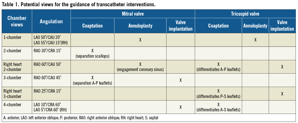
The heart can be described by a set of fluoroscopic chamber views (1-, 2-, 3-, and 4-chamber views). Figure 1 summarises these views and their relationships with the valvular apparatus for both the left and the right side of the heart. Table 1 summarises the potential views of interest for interventional procedures targeting the mitral and tricuspid valves.
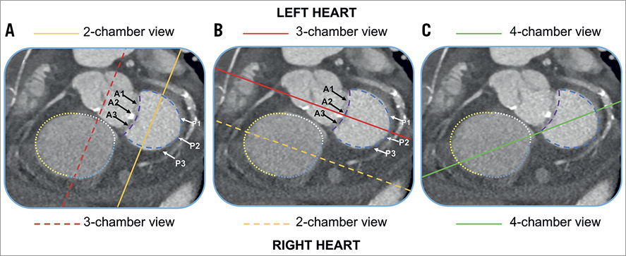
Figure 1. Fluoroscopic standardised views of the left and right side of the heart. The one-chamber (short-axis) view (blue panels) shows the en face view of the mitral and tricuspid annulus seen from the ventricular side. The attachment of the anterior mitral leaflet (dashed purple lines) and posterior leaflet (dashed blue lines) are reported in each panel. The black arrows correspond to the scallops (A1, A2, A3) of the anterior mitral leaflet. The white arrows correspond to the scallops (P1, P2, P3) of the posterior mitral leaflet. The attachments of the anterior (yellow dotted line), posterior (blue dotted line) and septal (white dotted line) are shown in each panel. The solid lines correspond to the different chamber views. A) The solid yellow line represents the plane of the two-chamber view for the left side of the heart, which corresponds to the three-chamber view for the right side of the heart (dashed red line). B) The solid red line represents the plane of the three-chamber view for the left side of the heart, which corresponds to the two-chamber view for the right side of the heart (dashed yellow line). C) The solid green line represents the plane of the four-chamber view, which is identical for both the left and the right side of the heart. A: anterior; P: posterior
Left heart chamber anatomy
Figure 2 shows the optimal projection curves for the aortic and mitral valves, and it summarises the main fluoroscopic, MSCT and echocardiographic views describing the chamber anatomy of the left side of the heart.
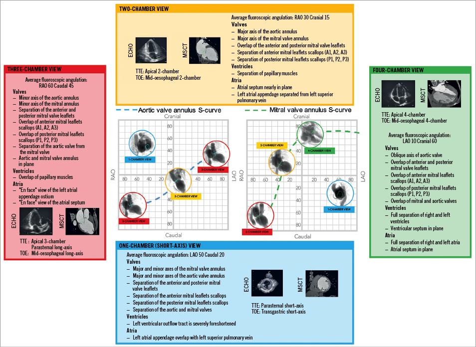
Figure 2. Multimodality imaging of the left side of the heart, aortic and mitral valve. The optimal projection curves of the aortic and mitral annulus are plotted as a blue dotted line (aortic valve annulus) and green dotted line (mitral valve annulus). The region of fluoroscopic angulations corresponding to each of the chamber views is indicated by circles. The panels correspond to the two-chamber (yellow), three-chamber (red) and the four-chamber (green) views. Each panel presents the matching echocardiographic and MSCT images corresponding to the fluoroscopic view of interest (circles). LAO: left anterior oblique; MSCT: multislice computed tomography; RAO: right anterior oblique; TOE: transoesophageal echocardiography; TTE: transthoracic echocardiography
Aortic valve
The aortic root is the continuation of the left ventricular outflow tract, extending from the basal attachment points of the aortic valve leaflets to their peripheral attachment at the level of the sinotubular junction. Its components are the valvular leaflets, the fibrous interleaflet triangles and the sinuses of Valsalva. The three leaflets form the limits of the right, left, and non-coronary aortic sinuses. While performing transcatheter aortic valve replacement (TAVR), operators focus on two main aspects: the virtual plane of the aortic valve annulus and the relative position of the sinuses of Valsalva.
The attachment line connecting the basal attachment points of the three aortic valve leaflets creates a so-called virtual ring, which represents the aortic valve annulus7. Rarely circular, the annulus shows a major and a minor axis which can be appreciated by analysing the MSCT8. While in the catheterisation laboratory using a 2D imaging technique, such as fluoroscopy, the appearance of the aortic annulus and its dimensions vary depending on the viewing angle used by the operator. The minor axis can be seen in a three-chamber view, by positioning the C-arm in an extreme RAO projection with a moderate CAU angulation (average angulation: RAO 70°/CAU 50°). This view can be useful for the sizing of the balloon used for predilatation of the valve or plain balloon aortic valvuloplasty. The major axis of the aortic annulus is provided by a mild LAO projection with a minimal CRA/CAU angulation (average angulation: LAO 15°/CRA 5°).
While performing TAVR, particular interest is often directed towards selecting a view showing the right coronary sinus between the non-coronary and left coronary sinuses to obtain a projection of the aortic annulus in plane and to achieve correct placement of the prosthesis. This view is obtained using a minimal LAO projection with minimal CRA/CAU angulation (average angulation: LAO 10°/CRA 0°).
Mitral valve
The mitral valve complex consists of different components: (1) the tendinous chords, (2) papillary muscles, (3) the left atrioventricular junction, and (4) the valvular leaflets. The mitral valve presents two leaflets. Depending on whether they are described following a classic or an attitudinal description (based on the anatomical axes of the body) the leaflets can be described respectively as anterior, aortic or anterosuperior and posterior, mural or posteroinferior. Following the Carpentier classification for each, leaflets can be described in terms of scallops: three in the anterior leaflet (A1 to A3), facing the three corresponding counterparts in the posterior leaflet (P1 to P3). With respect to an attitudinal approach and using the central segment (A2P2) as reference, the A1P1 and A3P3 portions of the valve are located superoposterior and inferoanterior, respectively. The use of fluoroscopic chamber anatomy can be helpful in guiding the precise positioning of the delivery catheter and devices during a transcatheter procedure targeting the mitral valve, in particular edge-to-edge mitral valve repair. Two views are of particular interest while using this technique.
THE FLUOROSCOPIC TWO-CHAMBER VIEW (FIGURE 1A)
This view describes the major axis of the mitral valve and it allows differentiating among the overlapped A1P1, A2P2 and A3P3 segments, an aspect of particular importance during the placement of clips. The two-chamber view can be obtained by using a mild RAO projection with a mild CRA angulation (average angulation: RAO 30°/CRA 10°). Transthoracic echocardiography can demonstrate a two-chamber view using an apical two-chamber view. A mid-oesophageal two-chamber view can achieve the same result while using transoesophageal echocardiography.
THE FLUOROSCOPIC THREE-CHAMBER VIEW (FIGURE 1B)
A fluoroscopic three-chamber view provides the maximal separation between the anterior and posterior leaflets of the mitral valve and it could play a role, together with echocardiographic guidance, in achieving correct grasping of the two leaflets. This view can be obtained by placing the C-arm in an extreme RAO projection with moderated CAU angulation (average angulation: RAO 60°/CAU 45°). In this view, both the anterior (A1-A2-A3) and posterior (P1-P2-P3) scallops appear overlapped, preventing precise positioning of the device along the mitral commissure. The right heart three-chamber view can be obtained during transthoracic echocardiography by using a parasternal long-axis view and with transoesophageal echocardiography using a mid-oesophageal long-axis view. In this fluoroscopic projection, the aortic and mitral valves are separated and in plane, and it is possible to observe the aortic-mitral curtain separated from the left atrium and the aortic root. Therefore, the use of the three-chamber view could be useful to assess any possible interaction between the prosthesis and left ventricular outflow tract during transcatheter mitral valve replacement or valve-in-valve interventions, preventing the potential risk of obstruction.
Right heart chamber anatomy
Figure 3 shows the optimal projection curves for the tricuspid valve. It summarises the main fluoroscopic, MSCT and echocardiographic views describing the chamber anatomy of the right side of the heart.
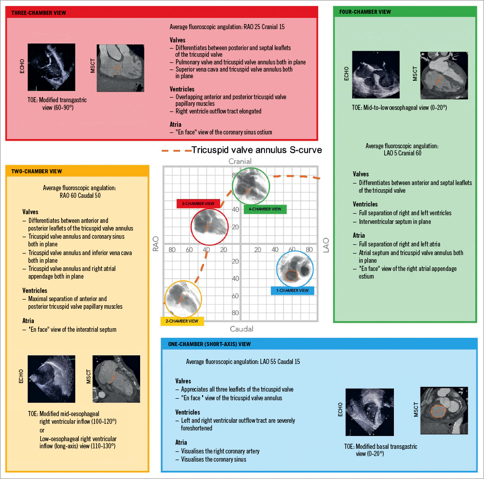
Figure 3. Multimodality imaging of the left side of the heart and the tricuspid valve. The optimal projection curve of the tricuspid annulus is plotted as an orange dotted line. The region of fluoroscopic angulations corresponding to each of the chamber views is indicated by circles. The panels correspond to the two-chamber (yellow), three-chamber (red) and the four-chamber (green) views. Each panel presents the matching echocardiographic and MSCT images corresponding to the fluoroscopic view of interest (circles). The conventional echocardiographic right heart two-chamber view was rotated 90° clockwise and inverted to reproduce the MSCT and fluoroscopic views. The conventional echocardiographic right heart three-chamber view was flipped upside-down and inverted right-left to reproduce the MSCT and fluoroscopic views. LAO: left anterior oblique; MSCT: multislice computed tomography; RAO: right anterior oblique; TOE: transoesophageal echocardiography; TTE: transthoracic echocardiography. Modified with permission from 13.
Tricuspid valve
The tricuspid valve complex can be divided into four components: 1) the fibrous annulus (with attached atrium and ventricle), 2) the three leaflets, 3) the papillary muscles, and 4) the chordal attachments. Considering the attitudinal orientation of the heart, the tricuspid valve leaflets can be designated posterior, anterior, and inferior corresponding to their traditional denominations of septal, anterior and posterior, respectively. As per the mitral valve, to avoid confusion, the current review maintains the standard nomenclature. The three tricuspid leaflets vary in both circumferential (annular) and radial size, with annular ratios of the anterior-to-septal-to-posterior leaflets corresponding to 1:1:0.759, in healthy subjects. Three commissures (anteroseptal, anteroposterior, and posteroseptal) separate the leaflets. It is essential to keep in mind that the size and shape of the annulus can influence the anatomical landmarks of the valve and therefore it is important to perform an accurate analysis of the MSCT during the procedural planning. For the tricuspid valve in particular, the presence of severe regurgitation could affect the dimensions of the annulus, which often dilates in a septal-lateral direction10.
Similar to the mitral valve, the optimal projection curve of the tricuspid valve annulus demonstrates a steep slope in the right anterior oblique region and presents an en face view in a left anterior oblique/caudal view.
Transcatheter interventions targeting the tricuspid valve (e.g., edge-to-edge tricuspid valve repair and percutaneous tricuspid valve annuloplasty) require accurate positioning of delivery catheters in relationship with components of the tricuspid valve (e.g., clips or screws). An in-depth knowledge and understanding of the configuration of the leaflets by using both echocardiography and fluoroscopy can be beneficial for the guidance of transcatheter procedures addressing the tricuspid valve. In the current review, we present the main fluoroscopic chamber views describing the tricuspid valve and the right side of the heart, together with their corresponding echocardiographic views.
THE ONE-CHAMBER (SHORT-AXIS) VIEW
The one-chamber (short-axis) view can be obtained, as for the mitral valve, by orienting the C-arm in a left anterior oblique projection with a variable degree of caudal angulation (average angulation: LAO 55°/CAU 15°). It corresponds to the en face view of the tricuspid valve and short-axis view of the right ventricle. In this view, it is possible to appreciate the trajectory of both the right coronary artery and the coronary sinus. While knowing the distance between the right coronary artery and the tricuspid valve annulus is essential to avoid complication during the placement of screws (e.g., percutaneous annuloplasty), the trajectory of the coronary sinus can be of potential interest for the placement of dedicated annuloplasty devices. The short-axis view can be matched with a modified (upside down) transgastric transoesophageal echocardiography view, seen from the ventricular side11. It is useful to differentiate the three leaflets of the tricuspid valve and potentially helpful in guiding procedures targeting these structures. During transoesophageal echocardiography, the one-chamber view can be appreciated using a basal transgastric window (0-20 degrees) or by using 3D acquisitions during transthoracic or transoesophageal echocardiography12.
THE TWO-CHAMBER VIEW
The two-chamber view can be obtained by placing the C-arm in a right anterior oblique projection with a variable degree of caudal angulation (average angulation: RAO 60°/CAU 50°). This view can help to identify the attachments of the anterior and posterior leaflets of the tricuspid valve to the atrioventricular junction (Figure 1B). The components of the subvalvular apparatus (i.e., the anterior and posterior papillary muscles) are maximally separated in the two-chamber view. Therefore, this particular angulation can facilitate the placement of dedicated devices targeting the right ventricular apex by navigating the ventricular space safely, while lowering the risk of entrapment in the subvalvular structures while the papillary muscles are maximally separated. The right-heart two-chamber view shows the interatrial septum en face and therefore could be useful in ruling out a possible overlap with the aortic root during transseptal puncture.
Transoesophageal echocardiography can demonstrate a two-chamber view using a mid-oesophageal right ventricular inflow view at 100-120 degrees (bicaval angle, rotated towards the right), a low-oesophageal right atrial view or a transgastric right ventricular inflow (long-axis) view at 110-130 degrees.
THE THREE-CHAMBER VIEW
The three-chamber view is obtained by placing the C-arm in an RAO projection with a mild degree of cranial angulation (average angulation: RAO 25°/CRA 15°). It allows visualisation of the attachments of the posterior and septal leaflets (Figure 1A). In this view, it is potentially difficult to discriminate between the anterior and posterior tricuspid papillary muscles, which appear overlapped. The right heart three-chamber view can be obtained during transoesophageal echocardiography using a transgastric view at 60-90 degrees.
THE FOUR-CHAMBER VIEW
The four-chamber view can be obtained by using a left anterior oblique (or a minimal right anterior oblique) projection with an extreme cranial angulation (average angulation: LAO 5°/CRA 60°). An extreme cranial angulation with the tricuspid valve in plane allows visualisation of the attachments of the anterior and septal leaflets (Figure 1C). The fluoroscopic four-chamber view corresponds to the classic apical four-chamber view on transthoracic echocardiography or the mid-to-low oesophageal view at 0°-20° on transoesophageal echocardiography.
Limitations
In the present review, we chose to provide general fluoroscopic angulations which were derived from analysis of multiple MSCT scans. Limited interindividual variability of fluoroscopic viewing angles for left-sided heart structures has been reported previously in the literature4. Similar interindividual variability in orientation can potentially be applied to the right-sided structures of the heart, in particular to the tricuspid valve, allowing the generalisation of fluoroscopic chamber views and orientation of cardiac structures. However, multiple comorbidities such as obstructive pulmonary disease, ageing and obesity or changes in the structure/shape of the heart (i.e., hypertrophy or dilatation) can influence the variability between patients in fluoroscopic viewing angles. To match views across imaging modalities, the echocardiographic images can potentially require some manipulation (up/down and/or left/right) and/or rotations (e.g., 90° from the traditional echocardiographic views).
Conclusion
While precise angulations should be obtained on an individual patient basis, the present review provides the interventional cardiologist with a general set of fluoroscopic angles and chamber views. This approach can potentially improve the understanding of the cardiac anatomy through different imaging modalities, and provide guidance during structural procedures. It lays the foundation for a common language among the players (i.e., interventional cardiologist and echocardiography operator) involved in such complex interventions.
Conflict of interest statement
N. Piazza is a consultant/proctor for HighLife, Medtronic and MicroPort, and is a consultant for Cephea. The other authors have no conflicts of interest to declare.