Abstract
Refractory angina is a growing problem, predominantly due to advanced coronary artery disease, associated with a reduced quality of life and an increased hospitalisation rate with a corresponding impact on healthcare resources. There is an unmet clinical need to be addressed by novel therapeutic approaches. Over the last few years, a treatment approach causing a controlled coronary sinus narrowing by implantation of a balloon-expandable, hourglass-shaped, stainless steel mesh (i.e., the coronary sinus Reducer) has arisen with promising initial short-term and midterm results, in terms of reducing angina and ischaemia burden and improving quality of life. Guidance with proper implantation algorithms and knowledge on how to address potential complications will improve interventional outcomes and foster a wider application of this novel therapeutic approach. In this review, we summarise the implantation technique, the causes of potential complications, and algorithms focusing upon their practical management, based on the experience of the authors.
Introduction
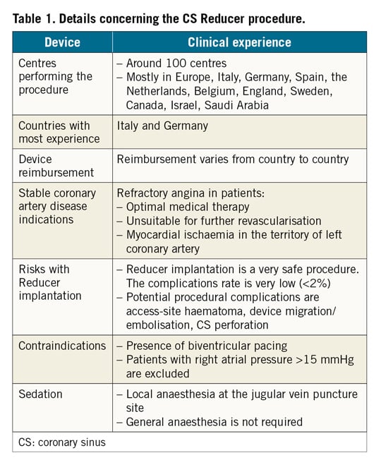
The coronary sinus (CS) Reducer™ (Neovasc Inc., Richmond BC, Canada) is designed to reduce disabling symptoms and improve quality of life of patients suffering from refractory angina (Table 1). A single randomised, sham-controlled clinical trial1 and a few observational studies2,3,4,5 have demonstrated the safety and efficacy of this novel device. The Reducer consists of a balloon-expandable, hourglass-shaped, stainless steel mesh, which is implanted in the CS to create a controlled narrowing of the lumen and a pressure gradient across it.

While the CS Reducer’s clinical efficacy on reducing angina burden is apparent, technical aspects of this procedure, including prevention and management of potential complications, have never been described systematically. In this review, we provide recommendations relating to the practical aspects of this procedure and we report potential procedural complications focusing upon their practical management. The technical aspects described below are based on our initial experience of approximately 500 cases performed by operators among the authors.
Coronary sinus Reducer device and the implantation procedure
The Reducer is a balloon-expandable hourglass-shaped stainless steel device, with flexible longitudinal struts without welding points (Figure 1). The device is delivered via an over-the-wire hourglass-shaped balloon catheter. The proximal and distal portions of the balloon have differing diameters so that once expanded they conform to the tapered anatomy of the CS. Two radiopaque markers (on the catheter shaft) outline the proximal and distal ends of the Reducer mounted on the deployment balloon. A third marker, located just proximally to the balloon, is used to assist the operator in visualising when the balloon section of the catheter is distal to the guide catheter (Figure 1).

Figure 1. Coronary sinus Reducer. A) The Neovasc coronary sinus Reducer system mounted on a balloon with radiopaque markers (arrows). B) Device during deployment.
THE PROCEDURE
Aims and considerations that should be taken into account during the procedure are presented in Figure 2. Based on the authors’ experience, patients undergoing Reducer implantation should be pre-treated with 75-100 mg aspirin daily for a minimum of 72 hours prior to device implantation in addition to either clopidogrel, prasugrel or ticagrelor. Dual antiplatelet therapy should be continued for at least one month after implantation. During the procedure, a bolus of unfractionated heparin (100 U/kg) should be administered after the introducer sheath is inserted into the jugular vein.
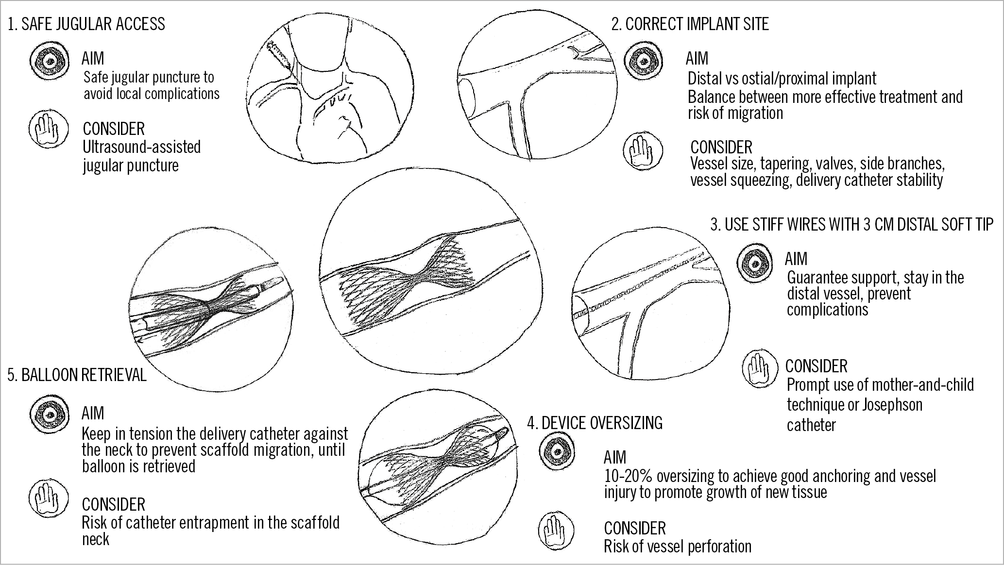
Figure 2. Coronary sinus Reducer implantation; aims and considerations.
The Reducer system kit (Figure 3) contains:
1) The Neovasc Reducer pre-mounted on a balloon catheter
2) A 9 Fr straight guide catheter (VISTA BRITE TIP™ 55 cm, no.598-943P; Cordis [now Cardinal Health], Milpitas, CA, USA)
3) A rotating haemostatic valve (MEDEX Inc., MX336LBP1)
The delivery system is designed to be used via the internal jugular vein; the right internal jugular access is preferable to avoid the tortuosity of the left. Sedation of the patient is not required for the procedure, only local anaesthesia at the jugular vein puncture site.
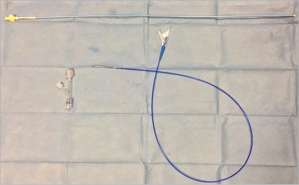
Figure 3. Coronary sinus Reducer kit. Device kit consists of a scaffold pre-mounted on a balloon catheter, a 9 Fr straight guide catheter and a rotating haemostatic valve.
VENOUS ACCESS AND PRELIMINARY MEASURES
Supplementary Appendix 1 and Supplementary Figure 1 provide information on the CS anatomy. After central venous access via the right jugular vein has been obtained, a 9 Fr sheath is introduced. A multipurpose diagnostic catheter is then advanced into the right atrium over a standard 0.035” wire and the right atrial pressure is measured. If the mean pressure is above 15 mmHg, the procedure is abandoned as the effect of the Reducer (aiming to increase the cardiac venous system pressure) is unlikely to be beneficial1. Another contraindication for Reducer implantation is biventricular pacing (Table 1). In this condition, the presence of the pacing lead in the CS makes the procedure technically challenging with the additional risk of lead fracture.
ANGIOGRAPHIC PROJECTIONS AND CORONARY SINUS ENGAGEMENT
The majority of CS ostia can be engaged in the left anterior oblique (LAO) 30° view, advancing and gently rotating a 5 or 6 Fr multipurpose catheter. Manual injection of radiopaque contrast medium via a 10 ml Luer-lock syringe can be used to confirm CS engagement. If engaging the CS is difficult with a multipurpose catheter, the use of an Amplatz Left 1, Amplatz Left 2, XB 3.5 or Josephson electrophysiology catheter may be considered. Importantly, if an Amplatz catheter is used to engage the CS ostium and to advance a wire distal into the vessel, it should not be advanced deep into the CS. Therefore, once the wire is advanced distal into the CS, the Amplatz catheter should be exchanged for the multipurpose catheter, which can easily be advanced deeper into the CS. If engagement of the CS is still difficult, visualising the CS anatomy by contrast injection into the left coronary artery in the venous phase in the 30° LAO view can be helpful. Rarely, in the most difficult cases, a coronary wire can be advanced into the left circumflex artery to act as a landmark.
CORONARY SINUS VENOGRAPHY AND SCAFFOLD RELEASE
After engagement of the ostium, a standard 0.035” wire is advanced distal into the CS and the catheter is then gently advanced over the wire as distally as possible. During this manoeuvre, the catheter can sometimes be dislodged into the right ventricle. With the catheter distally positioned in the CS, a venography is performed for CS sizing and to identify the location of collateral branches. Prior to contrast injection for venography, a small amount of contrast should be carefully injected to make sure that the tip of the diagnostic catheter is not located in a small branch. Device implantation is usually 1.5-3 cm distal to the CS ostium, where the vessel diameter is of adequate dimension for device deployment. The landing site should be chosen carefully to avoid side branches and, once chosen, can be re-identified by using bony landmarks. Then, a bolus of unfractionated heparin should be administered, and the Reducer system should be prepared (Supplementary Figure 2). It is important not to exceed a 20%:80% contrast/saline ratio inside the indeflator in order to facilitate balloon deflation and retrieval after scaffold deployment. A standard CS Reducer procedure is presented in Figure 4.
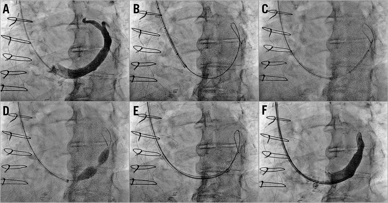
Figure 4. Standard coronary sinus Reducer procedure. A) Venography in left anterior oblique view (30°) with the catheter distal in the coronary sinus. B) A 0.035” wire is advanced distally in the great cardiac vein. C) Advancement of the Reducer system with the device protruding a few millimetres from the guide catheter. D) Reducer is deployed by inflating the delivery balloon at 4-6 atmospheres. E) Balloon catheter is retrieved by a simultaneous support of the 9 Fr guiding catheter. F) Final venography to confirm the correct position of the scaffold and exclude complications.
A 0.035” wire is then advanced within the catheter and placed distally in the great cardiac vein and the catheter is removed. Since adequate support is needed for the advancement of the Reducer system, we now routinely use the 0.035ʹ’ Hi-Torque Supra Core® peripheral wire (Abbott Laboratories, Abbott Park, IL, USA). The Hi-Torque Supra Core peripheral wire provides greater support and features a soft, shapeable radiopaque tip that helps to prevent venous injury.
The supplied 9 Fr guiding catheter tip should be manually curved to facilitate progression into the CS. It is important to advance the 9 Fr catheter and the device together, with the device protruding a few millimetres from the catheter in order to prevent vessel injury. Another strategy is to insert a 5 Fr multipurpose catheter into the 9 Fr catheter (“mother and child” technique) without the balloon in order to reach the distal part of the CS (Supplementary Figure 3). At this point, the 5 Fr catheter is removed and the balloon with the pre-mounted Reducer advanced. In cases of challenging anatomy, the use of a Josephson electrophysiology catheter with the mother and child technique may be needed (Supplementary Figure 4).
After reaching the landing zone, the guiding catheter is carefully retracted, exposing the Reducer system. The two distal markers, which identify the edges of the Reducer, enable correct positioning, using the bony landmarks previously identified. Importantly, before deploying the Reducer device, the 9 Fr guiding catheter must be withdrawn to the third proximal marker, so that the balloon can be fully expanded. Supraventricular and ventricular extrasystoles during CS engagement (related to catheter and device manipulation) are potential arrhythmias during the procedure.
The Reducer is deployed by inflating the delivery balloon at 4-6 atmospheres for at least 60 seconds. It is imperative to oversize the device by 10-20% relative to the CS. The CS sizing could be performed by visual estimation, but quantitative coronary angiography (QCA) is recommended especially for the first procedures. Oversizing helps to anchor the scaffold to the CS vessel wall, thus preventing device migration, and favours the activation of injury-induced tissue growth mediators that promote device endothelialisation. As valves of the CS might prevent proper scaffold oversizing, the proximal and distal portions of the Reducer should be implanted in valve-free segments. It is recommended to locate the narrowed centre segment of the Reducer on a valve, if possible.
BALLOON RETRIEVAL
Balloon retrieval must be performed with caution, preferably by two operators, to avoid displacement of the Reducer. A proposed technique is presented in Figure 5. This is achieved by advancing the guiding catheter to the narrow neck of the scaffold to provide support so that the balloon can be retrieved safely. This needs to be performed carefully due to the large profile of the balloon.
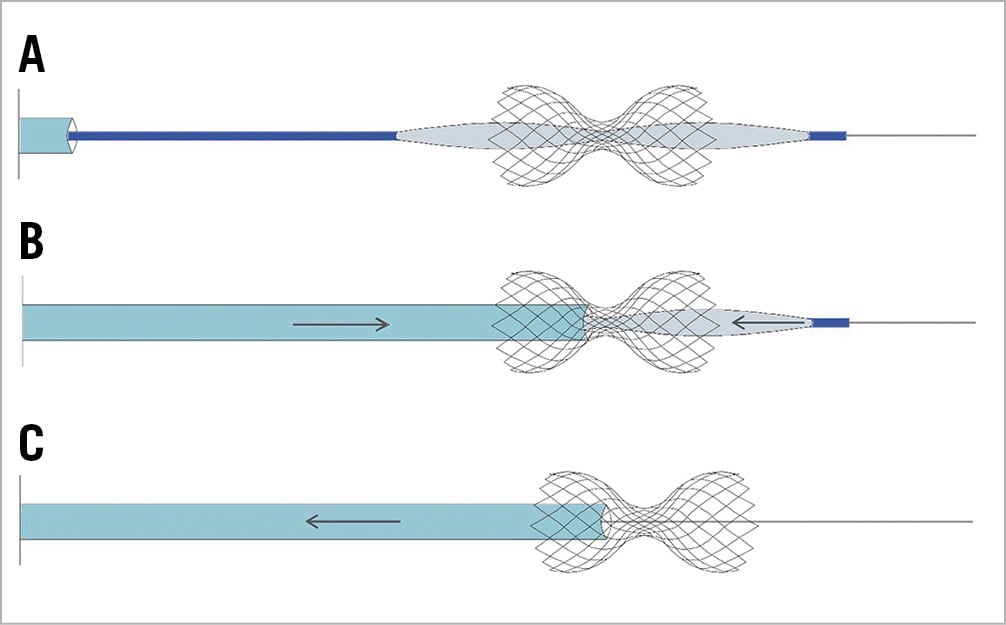
Figure 5. Proposed balloon catheter retrieval. A) The balloon is fully deflated, and a negative intraluminal pressure is established. B) The 9 Fr guiding catheter tip should be advanced against the neck of the scaffold. Retraction of the balloon catheter is accompanied by a parallel tension/support of the 9 Fr guiding catheter, supporting the Reducer during the manoeuvre. C) After passage of the balloon catheter from the narrow neck, the balloon is fully retrieved by the first operator. The 9 Fr catheter should be retrieved by the second operator to avoid entrapment inside the scaffold neck causing device displacement.
A final venography check is performed to confirm the correct position of the scaffold and to exclude potential complications.
Potential complications
Although evidence on CS Reducer safety is limited to the COSIRA trial and a few observational studies1,2,4,6, initial experience shows rare periprocedural or midterm device-related complications.
According to the technical steps of the Reducer procedure, our experience and a few case reports recently published, we here describe potential procedural complications (Table 1) including their prevention and management.
CS DISSECTION AND PERFORATION
Coronary sinus dissection and perforation are serious, potentially fatal, complications observed in patients undergoing electrophysiological procedures during the placement of the CS lead7,8,9,10 or during CS lead extraction11. Since the first CS Reducer implantation in 2004, only two cases of perforation have been reported so far with this procedure12. In the first case, the complication was addressed successfully with protamine sulphate administration to reverse the heparin effect and long semi-compliant balloon (5×12 mm) prolonged (five minutes) inflation at 10 atm in order to seal the perforation, while in the second case there was need for urgent surgery.
Coronary sinus dissection during Reducer implantation may happen because of manipulation of this “delicate” vessel. However, both catheter and wire are directed against the downstream flow during scaffold implantation, thus dissections rarely evolve into complete perforation and can usually be managed conservatively9,13.
Perforation might be caused by excessive oversizing during scaffold deployment and distal migration of the wire tip. Perforation might also be secondary to wire migration into a small side branch during device advancement; in such cases, when the scaffold is deployed across the main branch and a small side branch, it will result in CS perforation due to oversizing, at the site of the side branch origin (Figure 6).
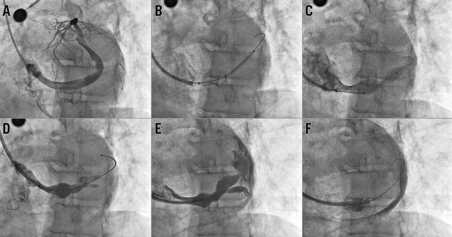
Figure 6. Coronary sinus perforation during Reducer deployment. Clinical case. A) Large CS directed upwards at the standard 30° LAO projection. B) Guidewire and catheter positioning. The guidewire tip is in a branch vessel. C) The Reducer was deployed by inflating the delivery balloon. The patient became hypotensive. D) & E) Coronary sinus venography revealing coronary sinus perforation. F) Contrast in the pericardial space. The patient was managed surgically and discharged a few days after the rescue operation.
Attention to the following steps may prevent perforation and dissection of the CS: advancement of the catheters over the wire; the use of a stiffer wire or mother and child technique; maintaining the wire in the distal CS segment and adequate scaffold oversizing in the correct position. Moreover, we recommend routinely ensuring adequate backflow from the catheter before performing any strong manual injection and confirming the correct wire position before device deployment. The first tip will avoid injection against the vessel wall or in a small branch, while the second one will guarantee device deployment in the correct position (avoiding small vessel damage in case of wire migration).
Management of CS perforation depends on its severity and associated haemodynamic compromise. It is based on the emergent requirement to stop coronary extravasation and ensure haemodynamic stability in the shortest possible time11,14.
Figure 7 illustrates a proposed algorithm, mainly based on the authors’ consensus, for the potential approaches to CS perforation during Reducer implantation and highlights the different management strategies.
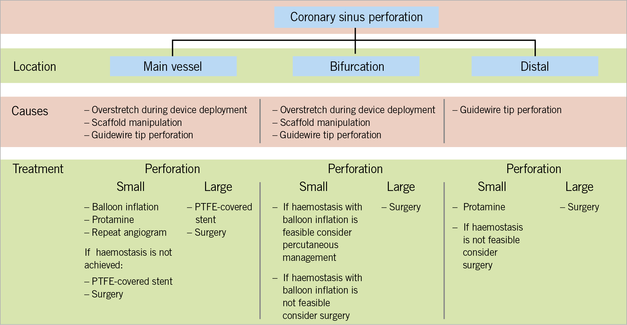
Figure 7. Proposed algorithm for coronary sinus perforation management.
Once this complication is confirmed, unfractionated heparin may be neutralised with intravenous administration of protamine. Moreover, a balloon of similar size or slightly larger than that of the vessel should be immediately positioned at the perforation site, to achieve immediate haemostasis15. The balloon should be placed at the perforation site or distally and should be inflated at the lowest possible pressure to promote haemostasis (as verified by contrast injection at regular intervals). When a large pericardial effusion is associated with tamponade, emergent pericardiocentesis is indicated8. Aspirated blood should immediately be re-infused into a vein to promote haemodynamic stability, especially in case of severe perforation.
While most perforations should resolve without intervention or should generally be treated with the proposed measures, cases of more severe perforation may be associated with persistent extravasation despite prolonged balloon inflations16. In these instances, the implantation of polytetrafluoroethylene (PTFE) stents should be considered17; however, emergency cardiac surgery may be required immediately16,18.
Another increasingly common cause of perforation is the inadvertent distal migration of guidewires (most commonly hydrophilic wires), resulting in tip-related perforation19. Although many of these perforations are small and self-limiting after protamine administration, the reverse venous flow and the distal location of the injury make subcutaneous fat or coils ineffective; thus, cardiac surgery should be considered if leakage persists and the patient remains haemodynamically compromised.
GUIDING CATHETER ENTRAPMENT INTO THE SCAFFOLD NECK
Balloon retrieval, following Reducer deployment, is performed with caution to avoid proximal displacement of the Reducer by the large profile of the deflated balloon. This is achieved by advancing the guiding catheter against the narrow neck of the scaffold before pulling the balloon into the guiding catheter’s tip, so that the catheter provides support and stabilises the Reducer and the balloon can be retrieved safely. Once the balloon is back into the catheter, the tip of the catheter is pulled back and away from the narrowed centre of the Reducer by pushing on the wire. This manoeuvre should prevent catheter tip entrapment within the narrowed centre of the Reducer. If the Reducer had been implanted with an inflation pressure >6 atmospheres (not recommended), the guiding catheter might cross the neck of the Reducer.
In rare cases of catheter tip entrapment, the first manoeuvre is an attempt to pull the guiding catheter back gently while pushing on the wire deep into the CS and trying to detach it from the scaffold. When an adequate scaffold oversizing has been performed, the guiding catheter should be easily detached by performing this manoeuvre. If it is unsuccessful and the catheter is still inside the scaffold, a second balloon may be advanced over the wire and inflated at the distal part of the device with the intention of trapping it. While the scaffold is trapped by the balloon, the guiding catheter should be gently pulled back (Figure 8).
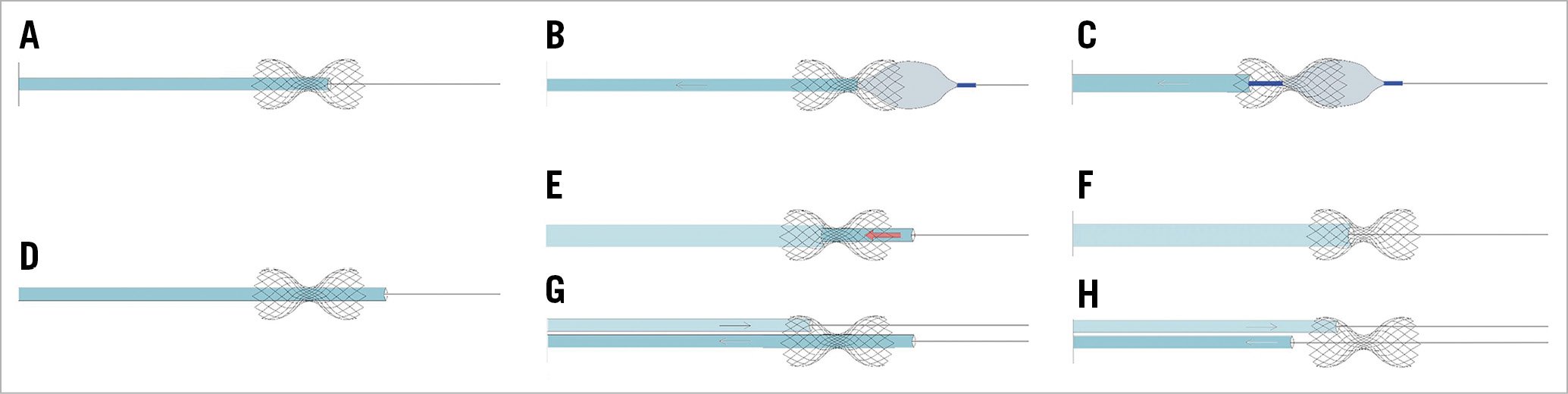
Figure 8. Guide catheter entrapment into the device neck. Proposed management techniques. A) Catheter entrapment into the device neck. B) A second balloon is advanced over the wire and inflated at the distal part of the device with the intention of trapping it. C) While the scaffold is trapped, the 9 Fr guiding catheter is gently pulled back without scaffold displacement. D) Catheter entrapment into the device neck, with catheter tip beyond the Reducer. Two different strategies may be helpful. E) A larger catheter is advanced against the scaffold neck over the 9 Fr guiding catheter utilising the “mother and child” technique. While the larger catheter is pushed against the neck, the 9 Fr trapped catheter is pulled back until it is fully retracted (F). G) As an alternative option, a second guide catheter is advanced to engage the CS. From the second guiding catheter a 0.035΄΄ wire is advanced through the scaffold struts at the level of the neck, then the second catheter is advanced over the wire against the scaffold neck. H) While the scaffold is maintained in situ pushing the second catheter, the first catheter is gently pulled back and detached from the scaffold.
If the guiding catheter went through the neck distal to the scaffold, two different strategies may be considered. A larger catheter may be advanced over the first against the scaffold neck; while the larger catheter is pushed against the neck, the second catheter should be pulled back. An alternative approach would be to get additional venous access and advance a second guide catheter into the right atrium and to engage the CS. Subsequently, a 0.035” wire is advanced from the second guide catheter into the scaffold struts at the level of the neck, then the second catheter is advanced over the wire against the scaffold neck. While the scaffold is maintained in situ pushing the second catheter, the first catheter should be pulled back gently and detached from the scaffold.
In most cases, percutaneous measures alone are successful; however, emergency cardiac surgery may be required20.
SCAFFOLD MIGRATION
Scaffold migration may occur in different phases of the procedure21. The proposed management algorithm for Reducer “loss” (on wire) is presented in Figure 9. When this complication occurs but the device is at least in part overlapping with the balloon, we recommend inflating the balloon and partially deploying the scaffold; then, a second balloon (sized according to the vessel diameter) should be advanced in order to expand the scaffold fully. When the dislodged device is not overlapping with the balloon, the interventional techniques utilised following stent loss retrieval in coronary arteries should be considered. Firstly, device retrieval with a gooseneck snare should be considered. If this proves unsuccessful, and the Reducer remains on the wire, a valid option is to try to advance a small balloon beyond the device, inflate it, and retrieve the scaffold by “dragging” it back with the balloon. Alternatively, a small balloon can be used to dilate the scaffold partially, making room for progressively larger balloons to expand the scaffold fully against the vessel walls. If the previous strategies fail, surgical removal should be considered, although in our and published experiences this has never been necessary.
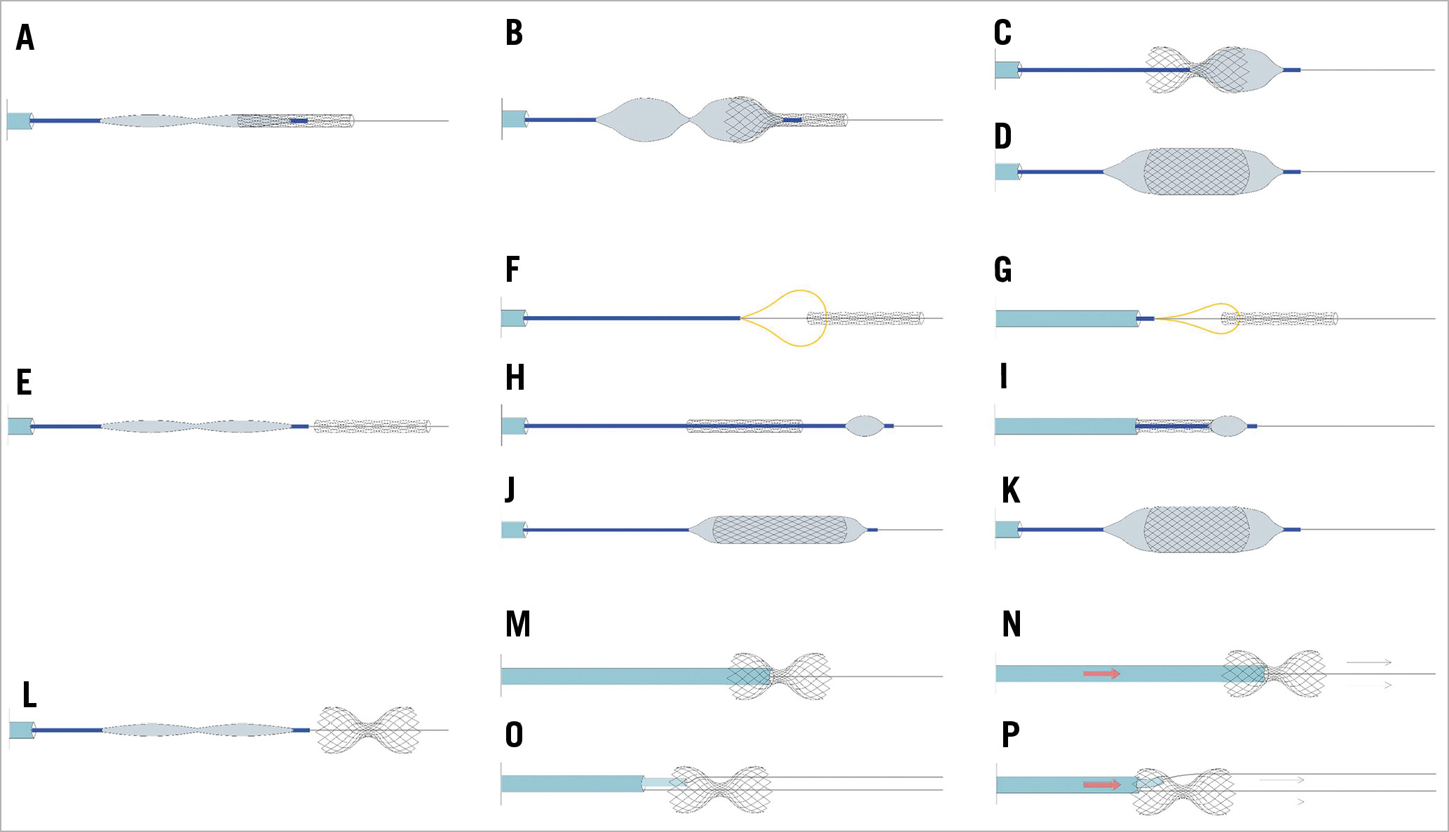
Figure 9. Coronary sinus Reducer loss on wire. Proposed management techniques. A) The migrated device is still at least partially overlapping the balloon. B) Reducer balloon inflation in order to deploy the scaffold partially. C) Attempt to advance and deploy a second balloon to expand the distal part of the device and reshape the scaffold or fully expand it and lose the narrow neck (D). E) When the uncrimped device is not overlapping the balloon, the use of gooseneck snares should be considered first (F & G). H) If this proves unsuccessful, and the Reducer remains on the wire, a small balloon can be advanced beyond the device and inflated, trying to retrieve the scaffold by “dragging” it back with the balloon (I). J) Alternatively, a small balloon can be used to dilate the scaffold partially, making room for progressively larger balloons to expand the scaffold fully against the vessel walls (K). If the previous strategies fail, surgical removal should be considered. L) Scaffold migration after deployment. In most cases, the migration of the scaffold out of the CS is prevented by the guidewire. M) A gentle attempt at re-advancing the scaffold in the correct position by pushing the guiding catheter against its neck (M & N). O) If this attempt is unsuccessful, a second 0.035” wire is advanced through the device mesh at the neck level, and a 5 Fr diagnostic multipurpose catheter is advanced over the second wire inside the 9 Fr catheter and pushed against the neck to advance the scaffold in the correct position (P).
Device migration may occur after its deployment (Figure 9, Supplementary Figure 5-Supplementary Figure 8). This occurs mainly during balloon retrieval when scaffold oversizing is insufficient, balloon refolding is not properly performed, and/or the guiding catheter is not advanced to the neck for support. In such cases, the migration of the scaffold out of the CS is prevented by the correct position of the wire in the distal vessel. A gentle attempt at re-advancing the scaffold in the correct position by pushing the guiding catheter against its neck may be performed (Figure 9M, Figure 9N, Supplementary Figure 5). If this attempt is unsuccessful, a second 0.035” wire is advanced through the device mesh at the neck level, and a 5 Fr diagnostic multipurpose catheter is advanced over the second wire inside the 9 Fr catheter and pushed against the neck to advance the scaffold in the correct position (Figure 9O, Figure 9P, Supplementary Figure 6). As described in the clinical case presented in Supplementary Figure 6, this manoeuvre may result in a distal crushing of the device. If this happens, after removal of the 0.035” wire, two 0.014” wires may be advanced into the distal CS and the crushed device may be post-dilated, inflating two coronary balloons simultaneously (Supplementary Figure 6).
In case of scaffold migration outside the CS with the device no longer over the wire, it should be snared (capturing it from the neck) and retrieved from an 18 Fr introducer placed through the femoral vein (Supplementary Figure 7, Supplementary Figure 8).
CORONARY SINUS THROMBOSIS
Coronary sinus thrombosis is an extremely rare and often fatal condition22,23. Acute CS occlusion is not well tolerated and immediate action to resolve the complication should be taken24. Such a complication has never been described with the Reducer. An old, experimental study showed that sudden occlusion of the CS was associated with a high operative mortality, while partial obstruction of the CS was associated with a lower mortality rate after a subsequent sudden occlusion of the left anterior descending artery and also diminished the extent of the infarction25, highlighting a “double-edged sword” phenomenon when referring to CS manipulation.
Acute coronary sinus occlusion increases pressure within the coronary venous system, inducing ischaemia, arrhythmia, progression to infarction, and sudden cardiac death. Chronic progressive occlusion has been described after electrophysiology procedures26. It has been well tolerated, probably due to the development of the Thebesian venous system.
Management of coronary sinus thrombosis, after ablation procedures, is poorly described, although thrombectomy and subsequent anticoagulation therapy have been employed22. Coronary sinus thrombosis during or following Reducer implantation is a potential complication, although no cases of CS thrombosis have yet been reported since 20071.
Conclusion
After the initial promising results of CS Reducer implantation, with efficacy in terms of reducing angina burden and reduction of myocardial ischaemia burden1,2,3,4,5, a forthcoming wider application of this approach should be expected. Although the Reducer procedure is safe1,2,3,4,5, a proper implantation algorithm and knowledge of how to address potential complications will improve patient outcomes and enable the wider application of this novel technique.
Conflict of interest statement
F. Giannini is a consultant for Neovasc Inc. S. Banai is the medical director of Neovasc Inc. The other authors have no conflicts of interest to declare.
Supplementary data
To read the full content of this article, please download the PDF.