In this chapter of Tools and Techniques Clinical, the implantation of the Direct Flow Medical transcatheter aortic valve is presented with the inner curve technique. The following is a summarised overview of the chapter. The complete, unabridged version with images and moving images is available online at: http://www.pcronline.com/eurointervention/74th_issue/66.
Background
There are currently numerous transcatheter aortic prostheses available commercially or in various stages of development1. Each one of these valves has its own peculiar implantation technique based mainly on its design, vascular access and the interactions between the prosthesis structure and anatomy of the patient.
The Direct Flow Medical® valve (DFM) (Direct Flow Medical Inc., Santa Rosa, CA, USA) is a non-metallic bovine pericardial aortic bioprosthesis composed of two expandable rings, a Dacron polyester cuff and interconnected tubing with flow valves2. It has unlimited repositionability and it is fully retrievable even after being implanted in its final position. Complete evaluation of prosthetic function by echocardiography and angiography can be performed before final valve fixation with a durable polymer. The device received CE mark approval in January 2013 and results of the DISCOVER trial have recently been published3.
An inner curve technique has proven to be safe and effective for the DFM prosthesis implantation and is described here. The technique is currently adopted as a standard to implant the valve and to date it has been successfully applied in over 500 cases worldwide.
Methods
IMPLANTATION: THE INNER CURVE TECHNIQUE
IMPORTANCE OF CO-PLANAR ANGLE
During positioning it is particularly important to orient the gantry properly in an optimal view parallel to the plane of the virtual basal ring. The C-arm should be oriented in order to have the right coronary cusp in the middle of the left and non-coronary cusps.
DIRECT FLOW VALVE TRACKING, UNSHEATHING AND UNFOLDING
After balloon valvuloplasty, the valve is unsheathed inside the left ventricle and the delivery sheath is withdrawn to the level of the aortic arch. The valve is fully pressurised at 12 atmospheres inside the LVOT. After fluoroscopic confirmation of complete valve expansion, the inflating device is pulled to negative pressure so that only the aortic ring completely deflates, leaving the ventricular ring fully pressurised with a mixture of saline and radiopaque contrast media at 12 atmospheres. The valve is now ready for positioning using the three steps of the inner curve technique.
THE INNER CURVE TECHNIQUE
Step 1 of the inner curve technique – valve orientation (in LV cavity) (Figure 1)
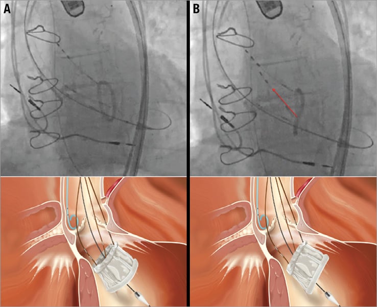
Figure 1. Inner curve technique step 1: valve orientation. The gantry is oriented in the co-planar angle with the annulus. The purpose of this step is to rotate the valve so that it appears as a single line under fluoroscopy. The starting and final positions of this step appear at A and B, respectively (lower panels are three-dimensional renderings of the fluoroscopic images). This is usually accomplished by pulling on a single positioning wire. Identification of the correct wire is done by observing the response in the size of the oval after gentle pulling (“wire testing”). If the fluoroscopic appearance of the oval-shaped ventricular ring tends to increase in size, the wire should be changed for the one that reduces its area. Once the ventricular ring of the valve appears as a line parallel to the valve plane, this step is over and the valve is ready to be positioned.
The fluoroscopic appearance of the prosthesis at this stage is that of a radiopaque oval shape (Figure 1A). Before beginning prosthesis withdrawal into the LVOT, this oval should be reduced to a straight line by pulling the appropriate positioning wire(s) (Figure 1B). Identification of the correct wire can be done by gently pulling and identifying valve movements in response to the pull (“wire testing”). If the oval tends to increase in size, a different wire should be selected. Alternatively, if the oval tends to reduce closer to a straight line, wire selection is correct and movement should be continued until the oval shape of the ventricular ring reduces to a straight line.
Step 2 of the inner curve technique – valve tracking
The tracking of the prosthesis in the LVOT should be done so that the portion of the device facing the inner curvature of the aortic arch reaches the aortic annulus first. It is important to use small movements of the valve and to correct the position of the bottom ring of the prosthesis if this has a tendency to lose alignment with the valve plane. Once the inner curve edge of the DFM valve reaches the annulus plane (Figure 2, blue dots), valve tracking in the LVOT should be stopped and tension maintained on that positioning wire. Keeping a good alignment of the ventricular ring of the valve during this phase is critical. This reduces the likelihood of a potential slipping of the device through the annulus (and the subsequent need for valve retrieval).
Step 3 of the inner curve technique – “closing the door” phase (Figure 2)
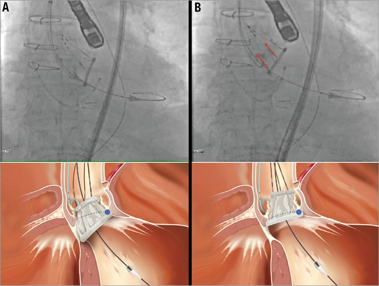
Figure 2. Inner curve technique step 3: “closing the door”. Tension is maintained on the positioning wire(s) located on the inner curvature portion of the valve (in this case wire number 2, identified by the two radiopaque markers on the fluoroscopic image, upper panel A and upper panel B). As long as tension is maintained, this part of the valve will act as a hinge point and allow the valve part on the outer curvature of the aorta to be pulled up to the annulus level (“closing the door”). The other wire(s) are pulled up for this to happen (in this case wires number 1 and 3 on the fluoroscopic image, red arrows on upper panel B). In its final position the lower ventricular ring of the valve should appear as a straight line positioned against the native annulus. The lower panels represent a three-dimensional rendering of the fluoroscopic images.
While tension is maintained on the inner curve wire, the part of the valve towards the inner curvature of the aorta will act as a hinge point. The part of the prosthesis on the outer curvature of the aorta will be pulled up to the annulus level (“closing the door”). In its final position the lower ventricular ring of the valve should appear as a straight line positioned against the annulus of the native diseased valve.
The correct fluoroscopic appearance of the DFM valve should show a fully expanded frame and it should be evaluated in multiple angiographic planes to confirm the correct circular or oval shape. There should be no indentation of the two rings, especially the upper aortic ring. The correct position of the device is reached when the ventricular ring is firmly against the basal part of the leaflets (aortic cusps’ nadir) occupying the space commonly identified as the “virtual basal ring”. The valve is now properly implanted in the final position and can be fully evaluated with multiple modalities (echocardiography, angiography, complete haemodynamic assessment) prior to final implantation. If desired, it can be repositioned in order to optimise the result or even be fully retrieved if necessary.
Conflict of interest statement
F. De Marco is a consultant for Direct Flow Medical Inc. A. Latib is an employee of Direct Flow Medical Inc.