Abstract
The 2023 European Bifurcation Club (EBC) meeting took place in Warsaw in October, and the latest evidence for the use of intravascular ultrasound (IVUS) and optical coherence tomography (OCT) to optimise percutaneous coronary interventions (PCI) on coronary bifurcation lesions (CBLs) was a major focus. The topic generated deep discussions and general appraisal on the potential benefits of IVUS and OCT in PCI procedures. Nevertheless, despite an increasing recognition of IVUS and OCT capabilities and their recognised central role for guidance in complex CBL and left main PCI, it is expected that angiography will continue to be the primary guidance modality for CBL PCI, principally due to educational and economic barriers. Mindful of the restricted access/adoption of intracoronary imaging for CBL PCI, the EBC board decided to review and describe a series of tips and tricks which can help to optimise angiography-guided PCI for CBLs. The identified key points for achieving an optimal angiography-guided PCI include a thorough analysis of pre-PCI images (computed tomography angiography, multiple angiographic views, quantitative coronary angiography vessel estimation), a systematic application of the technical steps suggested for a given selected technique, an intraprocedural or post-PCI use of stent enhancement and a low threshold for bailout use of intravascular imaging.
Since 2004, the European Bifurcation Club (EBC) has been consistently advocating for the improvement and standardisation of percutaneous coronary interventions (PCI) on coronary bifurcation lesions (CBLs) and the unprotected left main (LM) coronary artery. The annual 2-day EBC meeting facilitates multidisciplinary discussions, leading to the creation of a series of consensus papers covering general updates on CBL evaluation and treatment123, as well as specific technical problems456 encountered in bifurcation lesion stenting. The use of intracoronary imaging (ICI) modalities, such as intravascular ultrasound (IVUS) and optical coherence tomography (OCT), to optimise PCI on CBL and the LM artery has been a major and frequently debated issue. Thus, dedicated documents78 were generated aiming at promoting the use of IVUS and OCT for optimising technical results in these settings. However, the routine use of ICI requires appropriate training, is cost intensive, is limited by the need for specialised education, and may not be applicable in all clinical and anatomical scenarios. Although ICI is the best approach for achieving an optimal result in bifurcation stenting, the ultimate success of a bifurcation PCI procedure still depends on the final configuration achieved in the stented area. This, in turn, depends on the success of the specific distinct steps required for each bifurcation stenting technique. Finally, not all the possible technical imperfections that could potentially occur during bifurcation PCI are reasonably prevented, recognised or corrected by ICI alone. As a result, although ICI guidance should be regarded as a gold standard, angiography-guided PCI maintains a central role in bifurcation PCI practice. In the present paper, we report a series of tips and tricks for angiography-based optimisation of bifurcation PCI which have been proposed, discussed or shared during the various EBC meetings.
Key rules for coronary bifurcations
The universal law of conservation of mass (or flow) states that the sum of the total outflow must be equal to the inflow9. As a result, arterial geometry is intricately tied to its function. An experimental clinical study10 demonstrated the fractal nature based on this geometry and a linear relationship between the diameters of the mother vessel (the proximal main vessel [pMV]) and the diameters of the daughter vessels (the distal main vessel [dMV] and the side branch [SB]). This is expressed by the following formula: pMV=0.678*(dMV+SB)101112 (Figure 1). Likewise, for an arterial trifurcation, an appropriate linear relationship has been proposed: pMV=0.58*(dMV+SB1+SB2)13 (Figure 1). These validated and simple laws find application in the context of PCI to select balloons and stent sizes, particularly when the bifurcation/trifurcation has not been evaluated by ICI. It is noteworthy that a series of conditions (occluded branches, diffusely diseased bifurcation/trifurcation segments, etc.) may generate uncertainties about the size of a bifurcation/trifurcation segment during angiography-guided PCI. To facilitate the estimation of segment size under such circumstances, an online calculator has been developed (https://bifurc.eu/ebc-diameter-calculator/) allowing for the calculation of the theoretical nominal segment diameter after identifying the size of the other bifurcation/trifurcation segments. It should be emphasised that diseased coronary vessels have variable degrees of positive or negative remodelling, so estimations based on such formulae should be regarded as merely indicative.
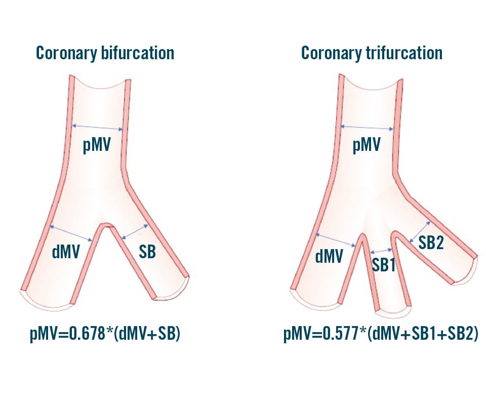
Figure 1. Schematic representation of coronary bifurcation and trifurcation with the corresponding Finet’s law formula explaining the relationship between the different segments. dMV: distal main vessel; pMV: proximal main vessel; SB: side branch
How to approach a bifurcation PCI in the absence of intracoronary imaging
Attempting to simplify and standardise the procedure as much as possible and limiting the number of implanted stents by using a stepwise provisional strategy remains the recommended strategy for the majority of true LM and non-LM CBLs1. This enduring recommendation of the EBC has recently been further supported by the results of the EBC TWO14 and EBC MAIN15 randomised trials. These studies have proven that a second stent was needed in only 20% of the cases randomised to a stepwise provisional approach and that fewer revascularisations occurred if the amount of metal was kept to a minimum1415. When SB stent placement is required after main vessel stenting, use of T-stenting, T and small protrusion (TAP) or culottes are the possible technical options3. A planned 2-stent strategy may be considered for bifurcation lesions when the atherosclerotic involvement of a relevant SB is extensive16 and/or the anatomical complexity is high, as estimated by the angiographic criteria outlined in the Bifurcation Academic Research Consortium (Bif-ARC) consensus document17. In bifurcations likely requiring two stents, the double-kissing (DK) crush technique has been promoted as a valuable strategy for systematic 2-stent implantation when the target vessel is the LM and PCI is performed by high-volume operators18. The DK crush technique, however, is complex and can only end safely with the two stents implanted and final kissing balloon inflation performed. Of note, it should be emphasised that, in the complex lesions enrolled in the EBC MAIN trial, the provisional technique, which was also performed according to the “inverted” strategy − implanting the first stent from the SB to the pMV, was highly effective15.
Optimised stent(s) expansion and apposition are the most likely main procedural surrogates for a good clinical outcome1. Accordingly, with increasing lesion complexity, adequate lesion preparation, particularly in the presence of a high burden of calcium, becomes crucial. The ICI evaluation provides invaluable information for lesion preparation, but this is not always readily available. The use of balloon-based techniques (cutting balloons, scoring balloons, high- and super-high-pressure balloons), atherectomy tools (rotational atherectomy, orbital atherectomy, laser) or intravascular lithotripsy should be considered in accordance with the recent algorithm proposed in the EAPCI Euro4C-PCR group consensus document19. The selection of an appropriately sized stent, tailored to accommodate the distinct bifurcation segments, is inherently challenging and warrants careful consideration. This is due to instances of notable stent malapposition, particularly in the pMV. Such malapposition is a systematic issue and poses a significant risk factor for subsequent stent deformation and/or abluminal wiring during the next stages of the procedure45. To overcome such complications, adequate expansion (from the proximal edge to the bifurcation core) of the pMV stent segment through the proximal optimisation technique (POT) becomes crucial. This specific technical step is recognised as pivotal for all major bifurcation stenting techniques12. Before completion of the procedure, high-pressure balloon post-dilatation of all stented segments of the coronary bifurcation is recommended1. This includes extensive use of non-compliant balloons in both 1- and 2-stent techniques and the systematic performance of high-pressure final kissing balloon inflation in 2-stent techniques1. According to the Bif-ARC endpoints classification, the goal of any angiography-guided bifurcation PCI is to achieve “procedural success”, defined as the proper placement of the stent(s) in the bifurcation segments and the absence of in-hospital significant cardiac events17. This definition translates into an optimal expansion of the implanted stents, along with the absence of procedural angiographic complications (dissections, thrombosis, etc.) potentially leading to adverse clinical events. Table 1 summarises the essential targets that should be pursued during bifurcation PCI.
Table 1. Key principles of bifurcation PCI promoted by the European Bifurcation Club.
| Essential target | Description |
|---|---|
| Keep the procedure simple and safe | - Choose a provisional stepwise stenting strategy |
| Respect the original bifurcation anatomy and physiology and aim to reproduce it | - Reconstruct the bifurcation anatomy with respect to the Finet, Murray and Huo-Kassab laws |
| Limit the number of stents | - Use a stepwise provisional strategy when the use of two stents is anticipated- Implant the first stent reversely from the SB to main branch when the SB is severely diseased- Use kissing balloons (opens the SB and centres the carina)- Implant a second stent only if needed (as T, TAP or culotte) |
| Do not stent the SB by default | - Consider the significance of the SB (CT scan, length, and diameter)- Conditions supporting SB stent implantation after provisional stenting of the main vessel:1. impaired TIMI flow in the SB2. significant stenosis (>70%) with angina and/or ECG changes3. extensive dissection (>type B) in the SB |
| Remember the step down in reference diameter from the proximal main vessel to the distal main vessel below the side branch take-off | - Size the first stent 1:1 to the distal main vessel reference diameter- Choose a stent diameter for which the platform accommodates expansion to the reference diameter of the proximal main vessel- Use of POT with balloon sized 1:1 to the proximal main vessel reference diameter- Be aware of geographical miss during POT (avoid bottle neck configuration of the stent) |
| Limit metal overlap | - Long segments and multiple layers of stents are associated with an increased risk of stent failure (ST and restenosis)- Presence of multiple layers of stent struts across the side branch ostium makes it more difficult to perform kissing balloon inflations- Reduce the stent overlap in DK crush and DK culotte |
| Achieve sufficient stent expansion | - Suboptimal stent expansion correlates with stent failure (ST and restenosis)- Stent expansion can accurately be estimated only by intracoronary imaging, but major underexpansion might be recognised by meticulous angiography revision and should be avoided- Optimal lesion preparation before stent implantation aids stent expansion- High-pressure non-compliant balloon post-dilatation of all stented segments of coronary bifurcation is recommended- Overdilate the stents by 5-10%, to compensate for recoil- Aim for: TIMI 3 flow in the main vessel and side branch; Minimal residual stenosis in the stented segments (DS <10%). |
| Avoid major stent malapposition | - Major malapposition is associated with increased risk of major safety events, including cardiac death, MI and ST- Stent apposition can accurately be estimated only by intracoronary imaging but major malapposition might be recognised by meticulous angiography revision and should be avoided- Stent malapposition is most often present in the proximal main vessel of a coronary bifurcation lesion due to suboptimal POT (undersized balloon used for POT)- The presence of stent malapposition in the proximal main vessel increases the risk of abluminal wiring and stent deformation during baseline and subsequent follow-up procedures- Use a stent-enhanced view when possible- Size the devices with respect to the vascular branching laws- Consider using contrast puffing during balloon inflations when a doubt of significant undersizing exists |
| CT: computed tomography; DK: double-kissing; DS: diameter stenosis; ECG: electrocardiogram; MI: myocardial infarction; PCI: percutaneous coronary intervention; POT: proximal optimisation technique; SB: side branch; ST: stent thrombosis; TAP: T and small protrusion; TIMI: Thrombolysis in Myocardial Infarction | |
The critical information provided by coronary computed tomography angiography
Coronary computed tomography angiography (CTA) has become the preferred non-invasive modality for assessing coronary artery disease in patients presenting with chest pain20. Consequently, the number of patients undergoing invasive angiography with prior CTA evaluation is increasing. In addition to luminal analysis for the assessment of stenosis severity, coronary CTA provides a comprehensive evaluation of atherosclerotic plaque composition2122 that may help in planning a PCI strategy, similarly to intravascular imaging. New advances, through the development of photon-counting computed tomography (CT) will further enhance the capabilities of non-invasive assessment.
Within the specific field of CBLs, the three-dimensional (3D) nature of CT provides pre-PCI identification of the optimal angiographic views, which may help during the procedure, and even facilitate virtual physiological assessment during Murray law-based angiographic assessment of quantitative flow ratio23. These benefits also concern the performance of the bifurcation PCI procedure. Indeed, CTA permits a careful analysis of the anatomical relationship between the plaque and the SB24, anticipating potential procedural challenges. The presence of non-calcified plaques, characterised by low attenuation, in the pMV or SB has been shown to predict SB occlusion25. Furthermore, the presence of calcium in the main vessel on the contralateral side of the SB anticipates difficulties in achieving symmetric stent expansion, leading to the risk of stent protrusion toward the SB ostium and of carina shift and branch occlusion25. The acquisition of such data before PCI assists preprocedural PCI planning, prompting adequate vessel preparation19. This becomes particularly critical in cases of complex bifurcations, with severe calcification, where coronary CTA can stratify calcified plaque based on its arc, length, and thickness in both the main vessel and the SB26. Another relevant aspect involves the quantification of the myocardial mass subtended by the main vessel and the SB27. As recently reported in the Bif-ARC document, this offers valuable insights into the clinical significance of the branch17. In this regard, the computation of blood flow from CTA, using dedicated algorithms (CT-derived fractional flow reserve [FFRCT]), provides information on the extent of flow reduction and the presence of ischaemia in different myocardial territories. This is most relevant in coronary bifurcations or trifurcations, where invasive functional assessment is more complex than in single diseased vessels (need for multiple measures, risk of extensive ischaemia during hyperaemia). Furthermore, FFRCT might allow the quantification of translesional pressure gradients across the bifurcation lesion, which, in addition to the classical physiological assessment at the distal segment of the vessels, enhances patient selection for bifurcation PCI28. Additionally, FFRCT technology has the potential to predict the outcomes of PCI in both the main vessel and in the SB (virtual stenting function). The current FFRCT planner technology supports provisional and 2-stent strategies, offering a comprehensive morphological and physiological approach to planning2930. Supplementary Figure 1 shows an example of advanced processing of CTA for planning PCI.
In conclusion, if CTA has been performed, it is strongly recommended that operators meticulously review the CTA images before CBL and LM PCI.
Updated coronary vessel sizing by angiography
Coronary angiography encounters limitations when applied to CBL due to its inherent two-dimensional (2D) nature. Consequently, pre-PCI angiography requires careful consideration to identify optimal angulations for visualising critical aspects, such as plaque distribution, vessel relevance, and subsequent post-PCI assessment. It is important to note that there is no single best projection capable of thoroughly evaluating the entire CBL. Certain views may be optimal for assessing lesion length, while others may offer superior insights into the SB ostium. In terms of stenosis severity and plaque distribution, visual assessment in CBLs is limited by its interoperator variability, with a tendency to overestimate SB disease significance31. Moreover, quantitative coronary angiography (QCA) analysis using the traditional single-vessel approach overestimates disease severity due to a failure to account for the natural step down in vessel diameter after the SB take-off. To overcome this limitation, 2D and 3D QCA analysis software dedicated to bifurcation has been developed32, and its use is strongly recommended.
Compared to traditional QCA, ICI demonstrated superior precision and accuracy in quantitative assessments. Comparative analyses between angiography and ICI modalities have consistently revealed that dimensions derived from IVUS and OCT are, on average, larger than those derived from QCA, with OCT providing the highest accuracy33.
These considerations emphasise the crucial role of ICI in optimising decision-making and interventional precision in the complex setting of CBLs. Despite the inherent limitations of angiographic interpretation, efforts to enhance our assessment should be considered. In a recent prospective randomised trial, an “adjusted” angiographic stent-sizing approach was employed for the first time. This protocol involved adjusting software-measured QCA reference vessel diameters by applying a 5-10% oversizing to create target diameters for stent sizing and post-dilatation34. Notably, bifurcation lesions, including those treated with 2-stent techniques, were included, demonstrating the feasibility of this approach34. Table 2 shows the estimation of “target” vessel reference diameters successfully adopted in the GUIDE DES trial34. Of note, only intravascular imaging is able to ascertain the true vessel size; it is impossible to recognise healthy references with angiography, especially in the presence of diffuse coronary artery disease.
Table 2. Target diameters of the reference segments obtained by adjusting QCA values in the GUIDE DES trial.
| QCA-estimated reference vessel diameter | Target vessel estimation |
|---|---|
| ≤3.5 mm | QCA-estimated reference vessel diameter+10% |
| >3.5 mm and <4.0 mm | QCA-estimated reference vessel diameter+6-9% |
| ≥4.0 mm | QCA-estimated reference vessel diameter+5% |
| DES: drug-eluting stent; QCA: quantitative coronary angiography | |
Technical basics for stent selection and deployment
THE DYNAMIC NATURE OF THE EXPANSION OF BALLOONS AND STENTS
An understanding of balloon and stent device characteristics can assist in the technical success of CBL PCI.
Coronary balloon construction differs according to the manufacturer, and their size is not fixed353637. This is due to their intrinsic elasticity causing a device-specific compliance (calculated as mm/atm). Two types of balloons are available in daily practice: non-compliant (small compliance) and semicompliant (intermediate compliance). The manufacturers provide pressure/diameter curves and define a nominal diameter (the “size” of the balloon on the packaging) achievable with a specific pressure. The nominal diameter of semicompliant balloons is determined at low pressures, typically ranging from 6 to 12 atmospheres (atm). This provides a higher capacity for diameter increase. On the contrary, the nominal diameter is achieved at a higher pressure with non-compliant balloons (14-16 atm). Bench test studies have shown that the pressure-diameter curves are specific to the balloon type and size3738. Importantly, the number of inflations affects the balloon behaviour. In particular, measured diameters are inferior to those declared by the manufacturer during the first inflation, similar at the second inflation, and superior for the third. For non-compliant balloons, the nominal diameter is determined with maximal pressure at the third inflation only (see Supplementary Figure 2 for examples of the behaviour of semicompliant and non-compliant balloons).
Stents offer minimal resistance to balloon inflation, indicating that, in the absence of external resistance, a stent’s expansion relies on the compliance of the stent’s balloon. Notably, vessel calcification is a significant factor contributing to stent underdeployment38. Manufacturers typically provide a range of potential expansion diameters based on the applied pressures of a stent’s balloon. These charts often include a range where the lower pressure is 7-8 atm.
It is essential to recognise that inflation pressure and inflation time significantly influence stent expansion. Firstly, if a stent’s balloon is inflated at pressures lower than 6-7 atm, stent expansion initiates, but it takes a longer time to complete39. Additionally, a series of observations documented that the stent diameter achieved at a fixed inflation pressure increases with inflation time40414243. Manufacturers’ charts typically indicate the pressure required to reach the stent diameter achievable with sustained (>20-30 sec) inflation at a specific pressure. Importantly, inflation times and numbers are cumulative, meaning that the same expansion can be achieved with either a prolonged inflation or multiple shorter inflations37. This property can be used to adapt the expansion modality (prolonged inflation or multiple short inflations) to the patients’ characteristics.
Overall, these characteristics play a crucial role in both the initial deployment of the stent and subsequent expansion through post-dilatation of the proximal or distal segments.
STENT ADAPTATION TO THE BIFURCATION ANATOMY BASED ON A STENT’S EXPANSION POTENTIAL
In the vast majority of bifurcation stenting procedures (from stepwise provisional to DK crush), a stent is implanted across the take-off of a branch vessel, implying the need to “adjust” the stent expansion to two vessel segments with different sizes. In other words, when such “crossover stenting” is performed, the stent size should be selected according to the dMV diameter, with consideration of the overexpansion required to achieve the pMV diameter using the POT with an appropriately sized balloon. Recently, dedicated bench tests demonstrated that the ideal POT is performed when inflating an appropriate balloon: diameter sized according to pMV reference diameter and length equal to the length of the stented pMV44. In clinical practice, this is rarely possible, as POT balloons are often shorter than the pMV stent segment, leading to multiple inflations in order to expand both the bifurcation area and the pMV up to the proximal stent edge. When multiple inflations with different balloon positions are performed, the balloon expansion sequence has been shown to influence stent geometry. In particular, bench tests documented that distal to proximal POT is associated with pMV stent elongation, a phenomenon which is preventable by performing proximal to distal POT44.
In addition to POT, it is crucial to give maximum attention to ensuring proper stent expansion in the dMV. Consequently, a distal post-dilatation, utilising an appropriately sized non-compliant balloon, is frequently necessary. This step is usually called “distal optimisation technique” (DOT). Because of the technical characteristics discussed earlier, the stent compliance chart should be carefully analysed, in order to facilitate the adaptation of the stent to any of the two segments. This can be accomplished by examining the technical characteristics of various stent platforms, taking into account not only the maximum expansion (necessary for achieving apposition in the proximal segment) but also the minimum expansion required to safely fit within the smaller distal segment. It is essential to choose a stent platform that is suitable for both the pMV and the dMV in order to achieve optimal stent deployment. Table 3 reports the “on-label” minimal expansion (with the corresponding atmospheres) and the “on-label” maximal expansions for some common stent platforms, demonstrating the wide range of options and supporting the process of stent selection and post-dilatation in the setting of bifurcations. Indeed, Table 3 shows how a particular bifurcation anatomy might be treated with different stent platforms, even among the options offered by the same manufacturer. Of note, a bench test study by Hikichi et al44 has demonstrated that choosing a bigger stent platform, with a nominal size close to the reference diameter of the pMV (instead of the segment), is associated with a more favourable stent configuration (Figure 2), resulting in a reduced incidence of incomplete stent apposition and better vessel coverage. In this regard, recognising the expansion characteristics has a greater relevance in specific conditions, such as “inverted” provisional techniques for the treatment of Medina type 0,0,1 large bifurcation lesions. For instance, these considerations have led to the development of the extreme concept of “stent underdeployment”, whereby the larger stent platform (sized according to the pMV or SB diameter) is preferred. Consequently, the stent is first implanted at below nominal pressure, avoiding overexpansion of the dMV. Subsequently, the pMV stent segment is expanded with a 1:1-sized balloon. This technique has been recently proposed to treat patients presenting a major size mismatch between the LM (large diameter) and proximal left anterior descending artery (LAD), with a novel extra-large drug-eluting stent (DES) platform45.
Table 3. Compliance charts for common DES platforms.
| DES platform | Nominal size range for each platform | Minimal expansion diameter (according to manufacturers’ chart) | Maximal overexpansion diameter with appropriately sized postdilatating balloon (on-label use) |
|---|---|---|---|
| XIENCE Skypoint1 | 2.0-3.0 mm | 2.05 mm (for 2.0 mm stent @ 8 atm) | 3.75 mm |
| XIENCE Skypoint1 | 3.5-5.0 mm | 3.36 mm (for 3.5 mm stent @ 8 atm) | 5.75 mm |
| Onyx Frontier2 | 2.0-2.5 mm | 1.89 mm (for 2.0 mm stent @ 7 atm) | 3.00 mm |
| Onyx Frontier2 | 2.75-3.0 mm | 2.50 mm (for 2.75 mm stent @ 7 atm) | 4.00 mm |
| Onyx Frontier2 | 3.5-4.0 mm | 3.20 mm (for 3.5 mm stent @ 7 atm) | 5.00 mm |
| Onyx Frontier2 | 4.5-5.0 mm | 4.10 mm (for 4.5 mm stent @ 7 atm) | 6.00 mm |
| SYNERGY XD3 | 2.25-2.75 mm | 2.05 mm (for 2.0 mm stent @ 8 atm) | 3.50 mm |
| SYNERGY XD3 | 3.0-3.5 mm | 3.05 mm (for 3.0 mm stent @ 8 atm) | 4.25 mm |
| SYNERGY XD3 | 4.0 mm | 3.88 mm (for 4.0 mm stent @ 8 atm) | 5.75 mm |
| SYNERGY MEGATRON3 | 3.5-5.0 mm | 3.18 mm (for 3.5 mm stent @ 8 atm) | 6.00 mm |
| Ultimaster Nagomi4 | 2.0-2.5 mm | 1.84 mm (for 2.0 mm stent @ 7 atm) | 3.50 mm |
| Ultimaster Nagomi4 | 2.75-3.0 mm | 2.56 mm (for 2.75 mm stent @ 7 atm) | 4.50 mm |
| Ultimaster Nagomi4 | 3.5-4.5 mm | 3.26 mm (for 3.5 mm stent @ 7 atm) | 6.25 mm |
| Orsiro Mission5 | 2.25-3.0 mm | 2.31 mm (for 2.25 mm stent @ 8 atm) | 3.5 mm |
| Orsiro Mission5 | 3.5-4.0 mm | 3.56 mm (for 3.5 mm stent @ 10 atm) | 4.5 mm |
| 1Abbott; 2Medtronic; 3Boston Scientific; 4Terumo; 5BIOTRONIK. DES: drug-eluting stent | |||
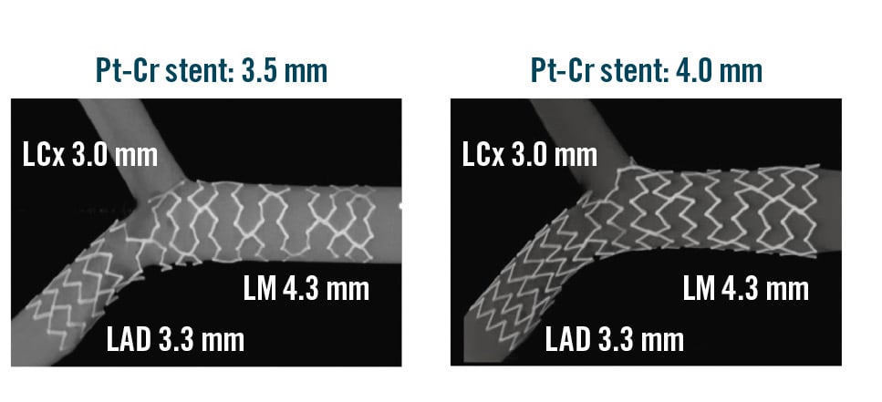
Figure 2. Bench test comparison of final stent conformation obtained by provisional stenting using two different stent platforms by the same manufacturer. A) SYNERGY (Boston Scientific) 3.5 mm×20 mm DES implanted at nominal pressures followed by POT and kissing. B) SYNERGY (Boston Scientific) 4 mm×20 mm DES implanted at low pressure followed by POT and kissing. Cr: chromium; DES: drug-eluting stent; LAD: left anterior descending artery; LCx: left circumflex artery; LM: left main artery; POT: proximal optimisation technique; Pt: platinum
Enhanced assessment of stent conformation during bifurcation PCI
The final goal of bifurcation PCI is to restore the native anatomy/physiology of the bifurcation and to minimise metal coverage (stented areas)17. From the first stent implantation to the procedure’s end, the stent(s) implanted into a CBL is required to conform to complex geometries through multiple steps of balloon modification. The sequence, the number and the quality of the different bifurcation PCI procedural steps are well known to influence the final conformation of the stent(s)46. The identification of the proper reference vessel size is pivotal (to drive adequate balloon selection) and undoubtedly more challenging in the absence of ICI. Stent post-dilatation (often performed through multiple non-compliant or semicompliant balloons) is of paramount importance to obtain adequate expansion and apposition. Therefore, appropriate balloon sizing is crucial, but there is a tendency to undersize in procedures not guided by ICI. For instance, significant undersizing of the POT balloon is a common cause of major malapposition in the pMV, leading to potential complications both during the procedure (abluminal rewiring, stent deformation)45 and in the postprocedural course47.
A recent innovation involves a technique where a small contrast injection is delivered during the stent post-dilatation phase, aiming to detect balloon undersizing in angiography-guided procedures4849. When contrast is able to bypass the inflated balloon, creating a “distal puff sign”, a substantial gap between the stent/balloon and vessel wall, indicating major malapposition, is likely. This phenomenon has been named the “POT-puff sign” when observed during POT49.
Of note, during bifurcation PCI, the adaptation of stent geometry at each step of any technique can easily be evaluated by stent enhancement tools (Figure 3). Although requiring a slight increased radiation dose, stent enhancement acquisition is extremely helpful whenever uncertainty regarding the achievement of appropriate stent geometry exists.
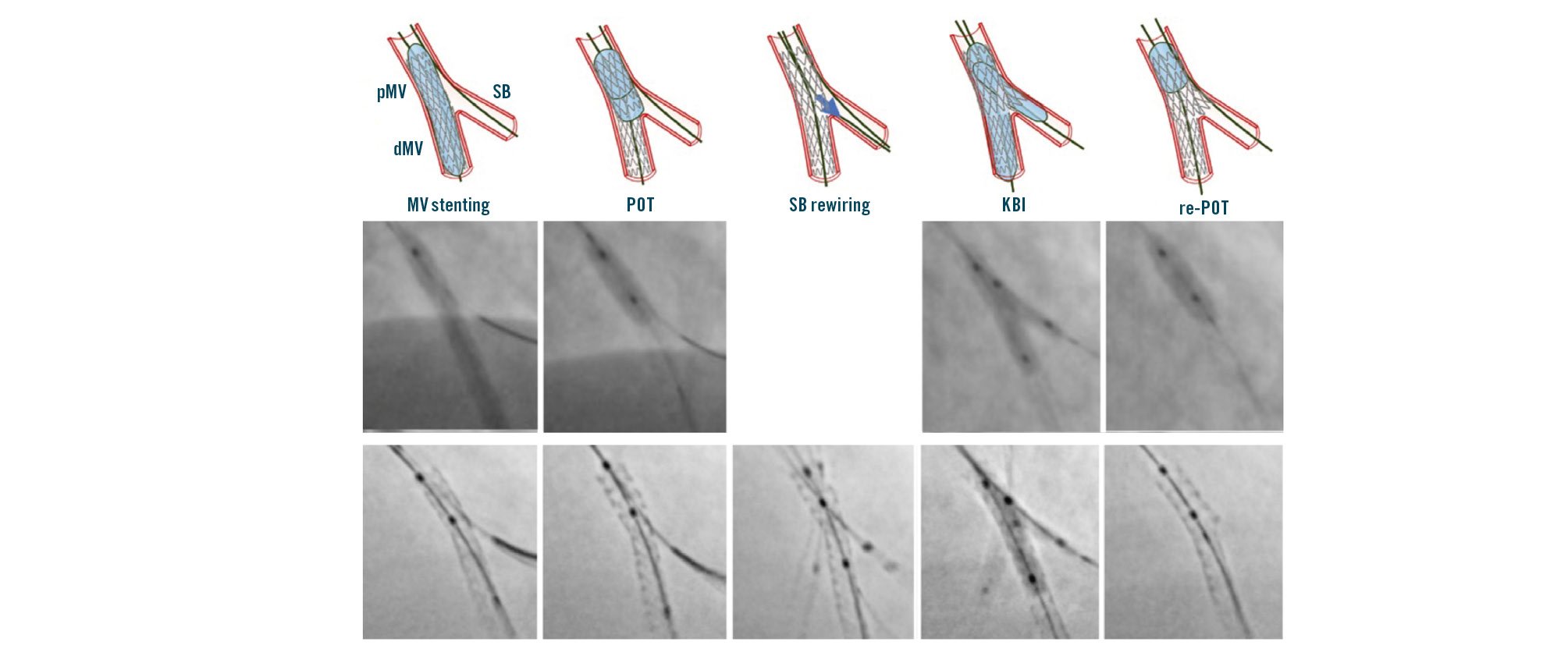
Figure 3. Sequence of stepwise provisional stenting and its clinical performance with step-by-step stent enhancement. dMV: distal main vessel; KBI: kissing balloon inflation; MV: main vessel; pMV: proximal main vessel; POT: proximal optimisation technique; SB: side branch
SB rewiring site check
SB rewiring50 is a key step in any bifurcation PCI in which the SB is treated, as the specific site where the wire crosses the stent struts influences the shape of the main vessel (MV) stent after SB dilatation. Accordingly, different rewiring sites are considered more appropriate depending on the different bifurcation PCI technique used. Current evidence supports the following concepts:
1. In stepwise provisional procedures (including those completed with double stenting according to T/TAP or culotte), the most favourable SB rewiring site is distal (close to the bifurcation carina)3;
2. In crushing procedures, SB rewiring should be non-distal (away from the bifurcation carina)3.
OCT represents the gold standard imaging modality to assess the rewiring site in bifurcation interventions8, and OCT-guided distal rewiring has been proven to be associated with more favourable stent healing51. Furthermore, a recent trial showing the superiority of OCT guidance in complex bifurcation PCI required, as part of the OCT-guided protocol, that operators confirm the ideal SB rewiring site52. In the absence of OCT guidance, it is self-evident that operators should pay maximum attention when manipulating the wire through the stent cells towards the SB, aiming at increasing the chance to rewire the most appropriate site according to the selected technique.
In the stepwise provisional technique, a pullback manoeuvre (from dMV to pMV) with an appropriately shaped wire tip increases the likelihood of distal rewiring350. Angiography may be used to confirm the achievement of the expected position. Figure 4 shows an example of distal rewiring assessed by angiography, resulting in an optimal OCT result. When the angiography is not reassuring, it can be useful to use a third wire to check if it is possible to wire closer to the carina.
In the setting of DK crush procedures, the appropriateness of stent crushing is considered pivotal to streamline a controlled rewiring3. In such cases, the wire tip should be shaped to be oriented toward the SB, in order to avoid distal crossing3. As soon as the wire crosses the crushed stent, fluoroscopy should be used to confirm the non-distal crossing site of the radiopaque wire tip (Figure 4).
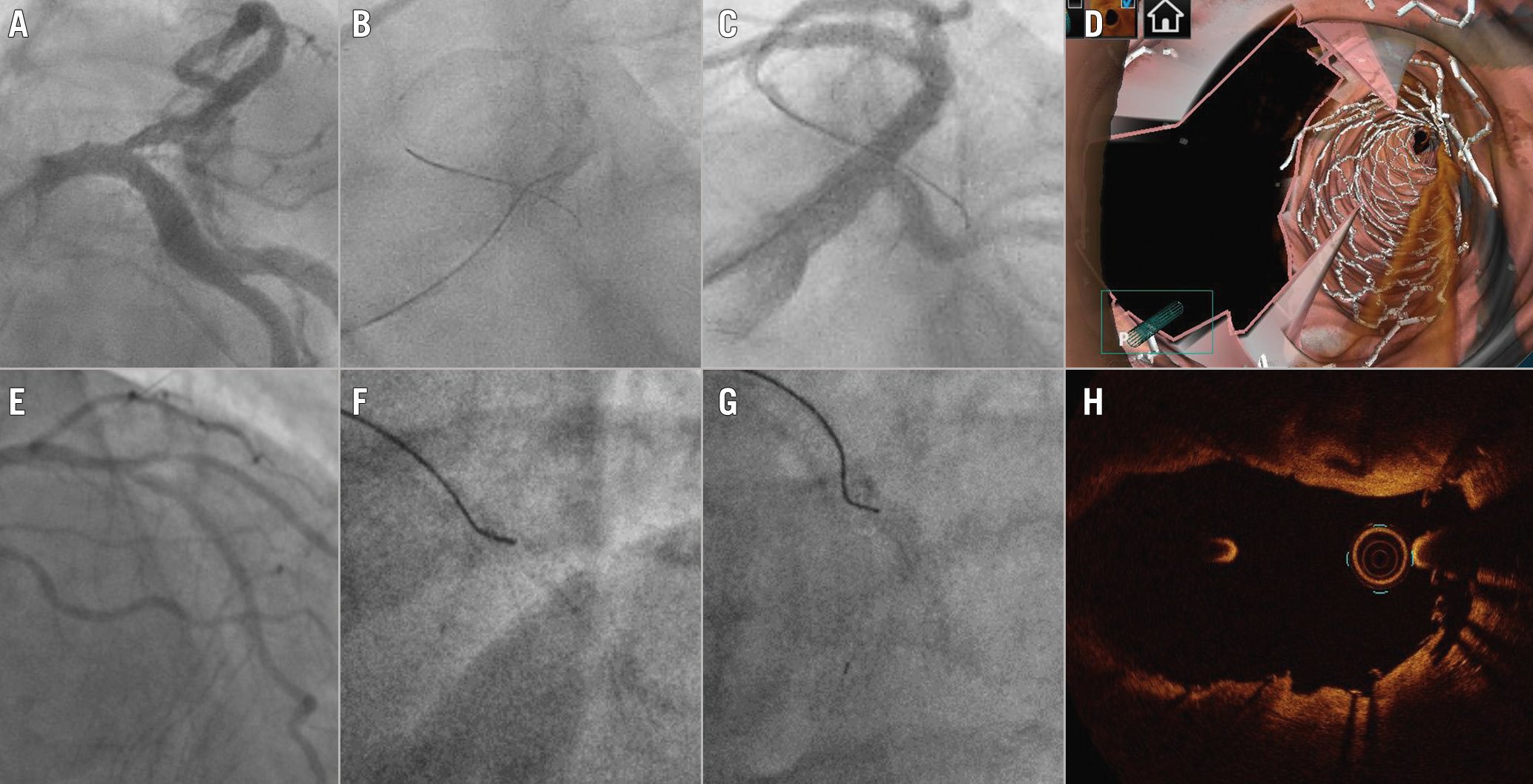
Figure 4. Optimal SB rewiring site check by angiography resulting in good OCT results after 1-stent (A-D) and 2-stent techniques (E-H). A) Baseline angiography in a patient treated by provisional. B) “Pullback rewiring” manoeuvre. C) Angiography confirming the achievement of distal rewiring. D) Post-PCI 3D OCT showing wide opening of the side branch. E) Baseline angiography in a patient treated by DK crush. F) Advancement of the wire towards the side branch ostium after balloon crush; G ) Fluoroscopic image confirming the “non-distal” rewiring site. H) Post-PCI OCT at the level of bifurcation showing optimal crushing of the side branch stent.
Procedural complications during angiography-guided PCI
Bifurcation stenting poses considerable technical challenges, and the absence of ICI guidance heightens the risk of complications while making it difficult to identify the underlying causes. Generally, adhering to a validated technique and following the recommended steps minimises the risk of suboptimal procedural outcomes46. However, the inherent complexity associated with bifurcation PCI, and the clinical conditions in which they are performed, often lead to stent imperfections. Their prompt recognition is crucial to mitigating the risk of major clinical pitfalls45. Following stent implantation and/or rewiring, any difficulty in balloon delivery within the MV or SB may reflect either stent deformation induced by the guide catheter or device interaction or imperfect stent geometry achieved in the previous steps of the bifurcation stenting techniques. As a common example, resistance when advancing the SB balloon through the MV stent struts may arise from inadequate POT, wire wrapping, or abluminal MV stent wiring. Prompt recognition of the underlying mechanistic cause allows the appropriate manoeuvres (removal of the SB wire, repetition of POT with a larger balloon) to be performed, avoiding further complications45. In such circumstances, stent enhancement imaging is highly informative, as displayed in Figure 5. Even in the presence of a satisfactory angiographic result, especially in the setting of 2-stent techniques, a post-PCI stent enhancement image acquisition has the potential to provide additional information about the real stent expansion/conformation achieved. Figure 5 shows some examples of incomplete SB ostium coverage and undesirable displacement of the neocarina detected by stent enhancement in the presence of a good angiographic result. A similar approach is advisable in the presence of intraprocedural thrombus formation (Figure 6).
Finally, whenever a procedural issue arises, and angiographic assessment or stent enhancement fail to elucidate its cause, operators should consider the use of ICI (IVUS or OCT according to operator experience) to better identify the aetiology and optimise the result.
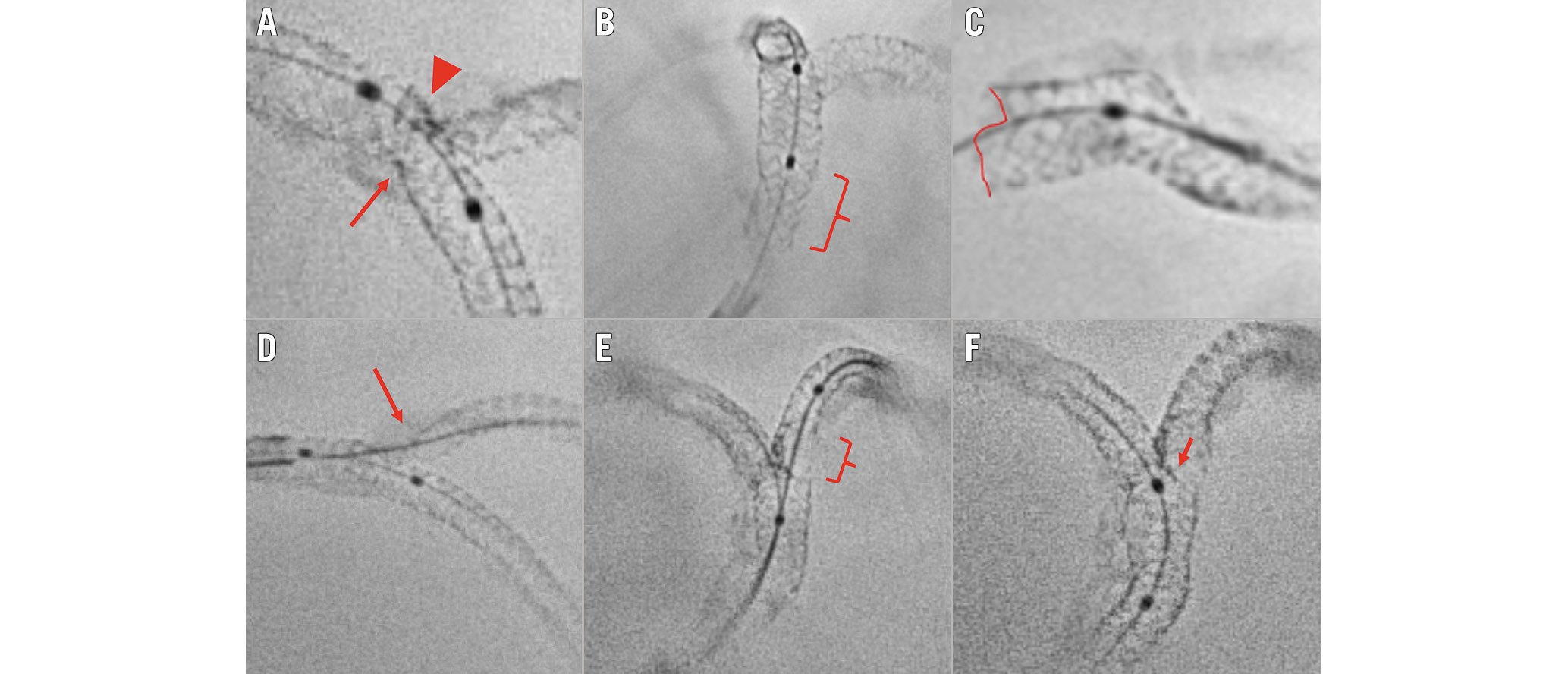
Figure 5. Suboptimal stent implantation revealed by stent enhancement imaging during bifurcation PCI. A) Stent underexpansion caused by the calcified plaque (arrow); the incomplete crush of the SB stent (arrowhead). B) Incomplete POT in the proximal segment of the LM stent (brace). C) Partial stent deformation caused by the guiding catheter at the LM ostium. D) Uncovered SB ostium (arrow) due to a too distal stent implantation. E) Abluminal SB rewiring and SB stent deformation after kissing balloon inflation (brace). F) Neocarina displacement (arrow) towards the SB ostium caused by a too distal final POT. LM: left main artery; PCI: percutaneous coronary intervention; POT: proximal optimisation technique; SB: side branch
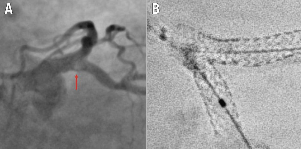
Figure 6. Example of recognised cause for intraprocedural thrombus formation during a 2-stent bifurcation stenting procedure. A) Intraprocedural angiography showing filling defect (arrow) at the SB ostium during a DK crush procedure on the LM. B) Stent enhancement revealing major deformation after kissing balloon inflation due to abluminal LM stent wiring. DK: double-kissing; LM: left main artery; SB: side branch
Conclusions
ICI is increasingly considered to provide gold standard guidance for CBL PCI, with evidence demonstrating superior results to angiography alone. However, education and access to technologies remain a major barrier to ICI adoption, and the vast majority of CBL PCI, worldwide, are undertaken with angiographic guidance alone. As shown in the Central illustration, the key points for achieving an optimal angiography-guided PCI include a thorough analysis of pre-PCI images (CTA, multiple angiographic views, QCA vessel estimation), a systematic application of the technical steps suggested for a given selected technique, an intraprocedural or post-PCI use of stent enhancement, and a low threshold for bailout use of intravascular imaging.
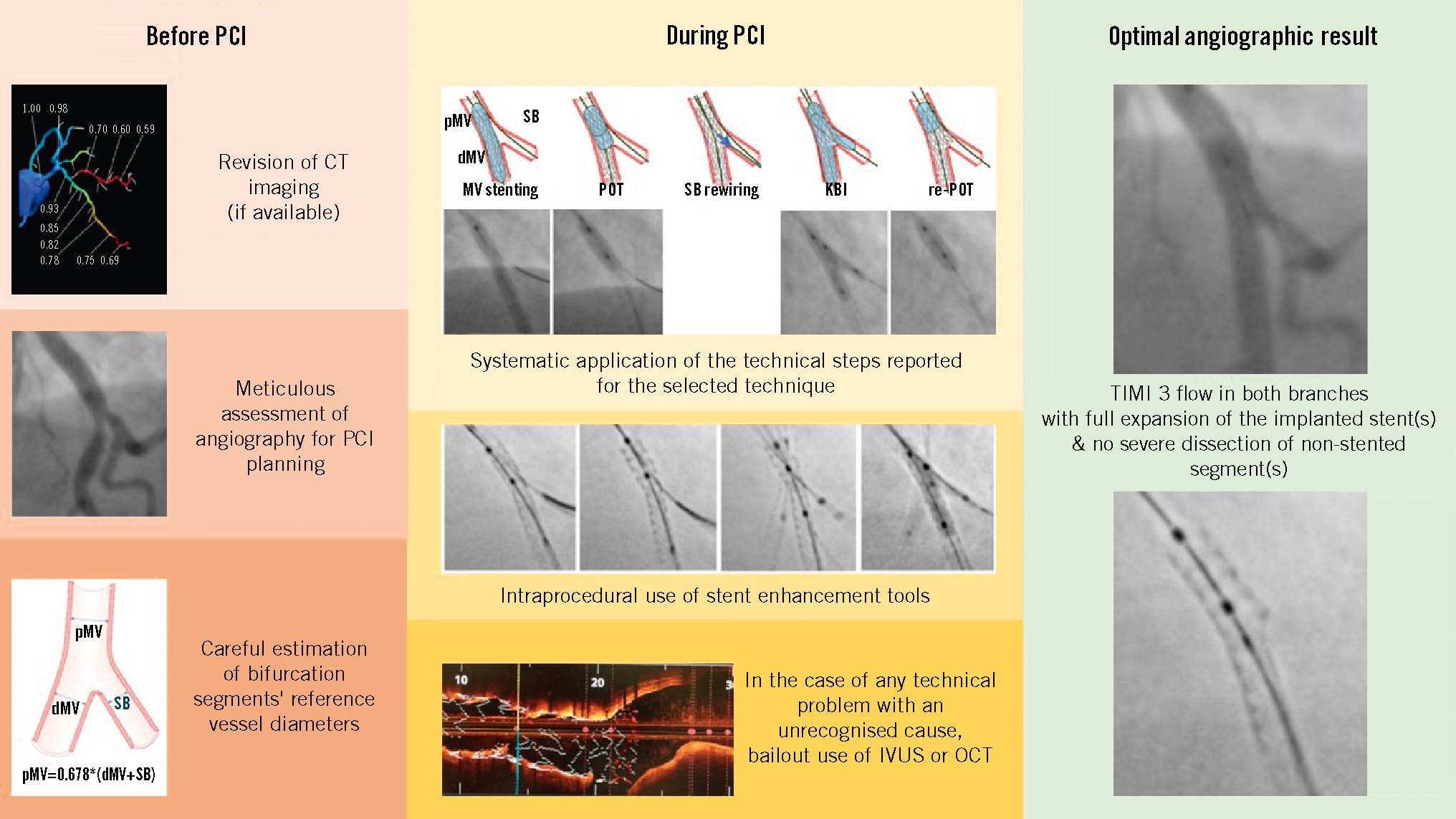
Central illustration. Key points for achieving an optimal angiography-guided PCI. The key points for achieving an optimal angiography-guided PCI include a thorough analysis of pre-PCI images (computed tomography angiography, multiple angiographic views, quantitative coronary angiography vessel estimation), a systematic application of the technical steps suggested for a given selected technique, an intraprocedural or post-PCI use of stent enhancement and a low threshold for bailout use of intravascular imaging. CT: computed tomography; dMV: distal main vessel; IVUS: intravascular ultrasound; KBI: kissing balloon inflation; MV: main vessel; OCT: optical coherence tomography; PCI: percutaneous coronary intervention; pMV: proximal main vessel; POT: proximal optimisation technique; SB: side branch; TIMI: Thrombolysis in Myocardial Infarction
Conflict of interest statement
F. Burzotta has received speaker fees from Medtronic, Abiomed, Abbott, and Terumo. J.F. Lassen has received speaker fees from Medtronic, Boston Scientific, Biotronik, and Abbott. R. Albiero has received speaker fees from Medtronic and Abbott. J. Legutko has received speaker fees from Abbott, Insight Lifetech, Philips, and Procardia. M. Pan has received speaker fees from Abbott, Boston Scientific, and Asahi. Y.S. Chatzizisis has received speaker fees/consultancy/research funding from Boston Scientific and Medtronic; and is co-founder of ComKardia Inc. T.W. Johnson has received speaker/consultancy fees from Abbott, Boston Scientific, Cordis, Medtronic, Shockwave Medical, and Terumo; and has received research funding from Abbott. A. Chieffo has received speaker/consultant fees from Abbott, Abiomed, Biosensors, Boston Scientific, Medtronic, and Menarini. G. Stankovic has received speaker fees from Medtronic, Abbott, Boston Scientific, and Terumo. M. Lesiak has received speaker fees from Abbott, Biotronik, Boston Scientific, Medtronic, Philips, and Terumo. T. Lefèvre has received minor fees from Terumo, Boston Scientific, Abbott, and Edwards Lifesciences. C. Collet has received a research grant and speaker fees and been on advisory board for Boston Scientific; has received a research grant and speaker fees from GE HealthCare, Insight Lifetech, Siemens Healthineers, HeartFlow, and Shockwave Medical; has received a research grant from Medis Medical Imaging, and Pie Medical; has stock options in Medyria; and has been a research director and equity holder of CoreAalst. O. Darremont reports support from Boston Scientific, Abbott, and Edwards Lifesciences. P.W. Serruys has received consulting fees from SMT, Meril Life Sciences, Novartis, Philips, and Xeltis. The other authors have no conflict of interest to declare.
Supplementary data
To read the full content of this article, please download the PDF.
