Abstract
Coronary artery bifurcation lesions comprise approximately 15-20% of all percutaneous coronary interventions (PCI) and constitute a complex lesion subgroup. Intravascular optical coherence tomography (OCT) is a promising adjunctive tool for guiding coronary bifurcation with its unrivalled high resolution. Compared to angiography, intravascular OCT has a clear advantage in that it depicts ostial lesion(s) in bifurcation without the misleading two-dimensional appearance of conventional angiography such as overlap and foreshortening. In addition, OCT has the ability to reconstruct a bifurcation in three dimensions and to assess the side branch ostium from 3D reconstruction of the main vessel pullback, which can be applied to ensure the optimal recrossing position of the wire after main vessel stenting. Recently, online co-registration of OCT and angiography became widely available, helping the operator to position a stent in precise landing zones, reducing the risk of geographic miss. Despite these technological advances, the currently available clinical data are based mainly on observational studies with a small number of patients; there is little evidence from randomised trials. The joint working group of the European Bifurcation Club and the Japanese Bifurcation Club reviewed all the available literature regarding OCT use in bifurcation lesions and here provides recommendations on OCT guiding of coronary interventions in bifurcation lesions.
Abbreviations
BRS: bioresorbable scaffold
CT: computed tomography
DES: drug-eluting stent
EEM: external elastic membrane
FD: frequency domain
FFR: fractional flow reserve
FKBI: final kissing balloon inflation
IVUS: intravascular ultrasound
LA: lumen area
LM: left main
MLA: minimum lumen area
MSA: minimum stent area
MV: main vessel
OCT: optical coherence tomography
OFDI: optical frequency domain imaging
PCI: percutaneous coronary intervention(s)
POT: proximal optimisation technique
QCA: quantitative coronary angiography
SB: side branch
TAP: T and protrusion
TCFA: thin-cap fibroatheroma
WSS: wall shear stress
Introduction
A coronary bifurcation lesion is a lesion occurring at, or adjacent to, a significant division of a major epicardial coronary artery1. Coronary artery bifurcation lesions comprise approximately 15-20% of all percutaneous coronary interventions (PCI)2 and constitute a complex lesion subgroup. Due to the complex three-dimensional structure of bifurcations causing overlapping and foreshortening, conventional angiography has an inherent limitation in the quantitative assessment of bifurcation lesions3.
Intravascular optical coherence tomography (OCT) is a promising adjunctive tool for guiding coronary bifurcations with its unrivalled high resolution (10-20 µm) (Supplementary Appendix 1). Currently, two systems are commercially available, OCT and optical frequency domain imaging (OFDI), using the same fundamental technology of optical frequency domain imaging, each with a different commercial implementation. Compared to angiography, intravascular OCT has a clear advantage in that it depicts ostial lesion(s) in bifurcation without the misleading two-dimensional appearance of conventional angiography such as overlap and foreshortening. In addition, OCT has the ability to reconstruct a bifurcation in three dimensions and to assess the side branch (SB) ostium from a three-dimensional (3D) reconstruction of the main vessel (MV) pullback.
Although all the potential benefits of adequately using the OCT information are highly appealing, its clinical value remains to be established. The currently available clinical data are based mainly on observational studies with a small number of patients (Supplementary Table 1). There are as yet few prospective clinical data to suggest clinical benefits of OCT guidance for bifurcation lesions (Supplementary Table 2). In the prospective randomised OPINION trial, comparing OCT and IVUS guidance in terms of patient outcome (n=829), 38% of lesions involved bifurcation4. However, no specific guidance protocol for bifurcation was available. In the ILUMIEN III trial, comparing IVUS and OCT guidance (n=450), bifurcation lesions requiring a two-stent strategy were excluded by protocol5. In the meantime, with the increasing complexity of bifurcation lesions and treatment, clinicians are more frequently implementing OCT imaging in bifurcation PCI6. Comparisons between OCT and IVUS in bifurcation lesions are summarised in Supplementary Table 3.
The European Bifurcation Club is an academic consortium created in 2004 whose goal has been to assess and recommend the appropriate strategies to manage bifurcation lesions. The Japanese Bifurcation Club was established and endorsed by the Japanese Association of Cardiovascular Intervention and Therapeutics in 2012 and shares the same aim as the European Bifurcation Club. This document provides the recommendations of the two bifurcation clubs on the OCT guiding of coronary interventions in bifurcation lesions.
– OCT may be of particular value in guiding bifurcation PCI, without the limitations of conventional angiography such as foreshortening or overlap.
OCT ACQUISITION IN BIFURCATION LESIONS
Current OCT catheters (Dragonfly™ OPTIS™ [Abbott Vascular, Santa Clara, CA, USA] and Lunawave® OFDI [Terumo Corp., Tokyo, Japan]) are used with a standard 0.014-inch steerable guidewire with a monorail system. During image acquisition, typically, contrast medium is injected at a speed of 3-5 ml/s. With a pullback speed of 10-40 mm/s, image acquisition usually finishes in 5-10 seconds. Recent consoles enable an automatic detection of luminal border as well as online 3D reconstruction, which could foster the understanding of the complex anatomy of bifurcations7,8.
In bifurcations, special attention is needed to acquire an optimal OCT image (Supplementary Table 4)9. Due to the difference in diameter of distal and proximal vessels, the scan range should be adjusted according to the size of the proximal vessel. The evaluation of a side branch ostium is often of interest; however, the guidewire shadow can hide the ostium partially or entirely. In such a case, repeat pullback after manipulation of the guidewire may be required. The nature of the bifurcation should be taken into account, including the tapering of the vessel according to conservation of flow and plaque distribution, especially on the opposite side of the carina. Predilatation of the SB is often necessary for successful OCT acquisition in the SB.
CO-REGISTRATION OF OCT AND ANGIOGRAPHY
The recent OCT consoles can co-register optical cross-section images with cineangiography acquired during a pullback, by automatic detection of the radiopaque marker of the optical lens on cineangiography. Practically, it is essential to acquire the cineangiography during the whole pullback, starting angiographic acquisition just before the start of pullback. In a complex bifurcation lesion, it is often a challenge to co-register OCT and angiography accurately due to the overlap and foreshortening of bifurcation anatomy on angiography3. It is important to select the angiographic view with the best visualisation of the bifurcation with minimal overlap and foreshortening.
The online co-registration could help the operator to position a stent in a precise landing zone according to the OCT finding, and potentially reduce the risk of geographic miss as well as subsequent adverse outcomes10,11. The DOCTOR fusion study, comparing frequency domain (FD)-OCT guidance and angiographic guidance in general PCI, demonstrated that, in the absence of such a co-registration, the target lesion (plaque) indicated by FD-OCT was not fully covered by the implanted stent in approximately 70% of cases10,12. Although co-registration may be of help in stent positioning, it should be noted that eventually the stent needs to be deployed using angiographic guidance alone.
– Use of online co-registration of OCT and angiography may facilitate the precise guidance of bifurcation PCI.
THREE-DIMENSIONAL OCT IN BIFURCATION
The application of 3D reconstruction of the coronary bifurcation has been described previously8. With two-dimensional (2D) imaging it is difficult and not always feasible to visualise the complex anatomy of the bifurcation and the effects of intervention. With 3D OCT it is easier to recognise the anatomical changes after intervention than with 2D OCT. For example, in the endoscopic 3D view of the coronary artery, it was clearly demonstrated that after stenting in the MV the carina was shifted towards the side branch, creating a stenosis at the ostium (Supplementary Figure 1)13.
ONLINE AND OFF-LINE SOFTWARE FOR 3D OCT
Recently, 3D reconstruction has become feasible online. The ILUMIEN™ Optis™ system (Abbott Vascular) has a 3D bifurcation mode, in which software automatically recognises the carina as well as side branch ostia with a diameter of ≥1.5 mm. With automatic stent enhancement, the recrossing point in bifurcation is depicted in a 3D view (Figure 1). In a “stent roadmap” view, the lumen profile reconstructed from automatic lumen delineation allows a superimposition of malapposed struts14. The Terumo OFDI console has online software of 3D imaging with stent enhancement, which enables online reconstruction within one minute (Figure 2)14.
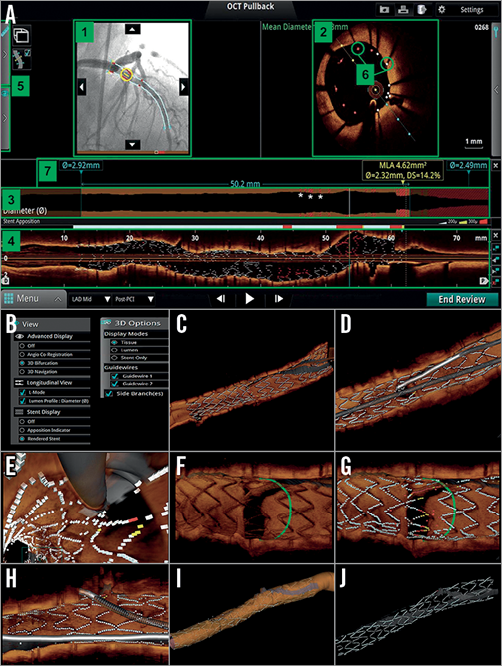
Figure 1. Overview of online 3D reconstruction. A) “Stent roadmap” indicates the location of the minimal lumen area and suggests the proximal and distal landing zones for the stent placement based on the mean lumen area measurements. At the same time bookmarks are provided on the co-registered angiogram to assist in the overall orientation. 1) Angio co-registration, 2) cross-sectional view, 3) lumen profile view, 4) longitudinal view, 5) fold-out tabs, 6) apposition indicators, 7) stent roadmap, *) invalid frame. Panels B to J represent an overview of online 3D OCT images reconstructed by the ILUMIEN™ Optis™ system (Abbott Vascular). B) In the dedicated panels for 3D reconstruction, the particular options such as “view” (i.e., longitudinal, stent display) and “display” (i.e., stent, tissue, lumen, and guidewires) are available for several types of 3D image. C) 3D navigation view with stent display. D) 3D navigation view with stent and guidewires. E) 3D navigation view (fly-through) with stent and guidewires. F) 3D bifurcation view with tissue display. G) 3D bifurcation view with stent display. H) 3D bifurcation view with stent and guidewires. I) 3D navigation view with lumen display mode. J) 3D navigation view only with stent display. (Reproduced from OCT Atlas, 2nd edition)
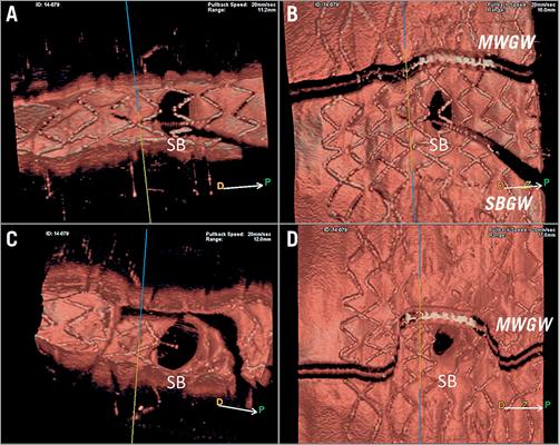
Figure 2. Online 3D reconstruction images by OFDI. Online 3D images reconstructed by OFDI (Lunawave® system; Terumo, Tokyo, Japan) are shown. A) Vessel view before kissing balloon dilatation (KBD). B) Carpet view before KBD. C) Vessel view after KBD. D) Carpet view after KBD.
The Medis company (Leiden, the Netherlands) has developed a dedicated OCT software, in which 3D angiography and OCT are co-registered. In addition, this software enables quantitative assessment of the side branch ostium by using an OCT pullback from the main branch (MB) in a cross-section which is perpendicular to the side branch centreline15. For precise sizing of a side branch ostium, OCT pullbacks could be performed in both the MV and SB, which is often challenging in clinical practice due to safety concerns including the use of an excessive amount of contrast media. Although OCT assessment in SB OCT pullback remains the gold standard, measurements of the side branch ostium performed online by cut-plane analysis of an OCT pullback of the MV have a high correlation with reference measurements performed in an SB OCT pullback and also lower errors compared with conventional analysis15. Use of such software is preferable since the insertion of the OCT catheter through the MV struts into the side branch is not always easy, may deform the stent and implies additional contrast medium (Figure 3). Quantitative assessment on 3D OCT is commonly used in clinical trials (Supplementary Table 5). The CAAS IV-LINQ software (Pie Medical, Maastricht, the Netherlands) provides the real-time co-registration of angiography with intravascular imaging, while CAAS IntraVascular software enables 3D reconstruction of the SB ostium on OCT.
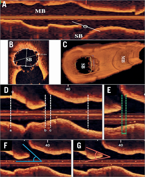
Figure 3. Analysis using reconstructed OCT images: cut-plane analysis using pullback from MV and angle measurement in side branch in longitudinal view. A) Measurements of the SB ostium can be performed in the main branch (MB) pullback (B) by cut-plane analysis. C) The 2D cross-section is adjusted to capture the true vessel morphology perpendicular to the SB centreline. Modified from Karanasos et al15. For angle measurement in the side branch (D), the specific longitudinal reconstruction image was determined when both carina and the SB ostium could be identified clearly, as well as showing the narrowest carina angle: (a) distal reference site, (b) carina tip, (c) proximal branching point, (d) proximal reference site. E) The length between the proximal branching point and the carina tip (BP-CT length). F) Side branch angle (SB angle). G) Carina tip angle (CT angle). Modified from Watanabe et al36.
– Whenever available, use of online 3D reconstruction is recommended to facilitate the understanding of complex coronary anatomy and device-vessel interaction during bifurcation PCI.
– Unlike with IVUS, 3D assessment of the ostial area from OCT pullback of the MV is a good substitute for a pullback from the SB.
PREPROCEDURAL LESION ASSESSMENT
Preprocedural assessment of lumen and plaque distribution in bifurcation on OCT may provide essential information on treatment indication and planning of bifurcation PCI. Although the functional assessment of stenosis is a standard of care for angiographically intermediate lesions, interpretation of fractional flow reserve (FFR) results is challenging, for example, in a bifurcation lesion with proximal stenosis, or downstream stenosis due to the so-called “branch-steal” phenomenon16. There are several cut-off criteria of OCT-derived minimum lumen area (MLA) to predict significant FFR; however, such a threshold should be used considering the distal myocardial mass beyond each branch of the bifurcation lesion. In other words, there is no single threshold to be used17-19. Conversely, functional assessment without anatomical information cannot predict the anatomical changes after stenting (e.g., carina shift), which is essential for bifurcation PCI planning.
Atherosclerotic change in bifurcation is influenced by distribution of wall shear stress. Coronary plaque was mostly present in low wall shear stress (WSS) regions20. In bifurcation lesions, plaque grows from the outer wall (low WSS) of the bifurcation towards the flow divider (high WSS). These findings were confirmed in an OCT study21, demonstrating that thin-cap fibroatheroma (TCFA) was localised predominantly in the region opposite the flow divider, whereas the flow divider was rarely affected. Lipid accumulation tends to develop in the zone opposite the side branch. In a multi-modality assessment of bifurcation with IVUS virtual histology and OCT, the proximal rim of the ostium of the side branch was identified as a region more likely to contain thin fibrous cap and a greater proportion of necrotic core22-24. However, it remains to be demonstrated how we can integrate this information to guide bifurcation intervention.
Assessment of calcification by OCT could indicate which lesion preparation should be performed. Since calcification does not scatter light, OCT could evaluate the circumferential extension and the depth (superficial vs. deep) of calcification. In general, extensive calcification on OCT is associated with suboptimal stent expansion, stent malapposition, and failure of device delivery10,25-30. The latter may be especially important for the delivery of a dedicated bifurcation device or bioresorbable scaffold with a large profile. For superficial and/or circumferential calcification, atherectomy using a rotablator or orbital atherectomy system may be preferred, whereas deep calcification may preferably be treated with a cutting or scoring balloon through incisions between calcified and non-calcified plaque10,31-34. However, whether the information on calcium by OCT may be used to select specific strategies aimed at improving final results still remains unproven.
OCT assessment of the preprocedural bifurcation angle could be derived from OCT pullback in the MV. The carina tip angle is measured in a longitudinal view of OCT of the MV pullback as an angulation of the proximity of the carina (Figure 3G). It has been demonstrated that the OCT-derived bifurcation angle has a good agreement with the computed tomography-derived bifurcation angle (mean bias=2.6, SD=11.4°)35. The preprocedural carina tip angle as assessed on OCT has an impact on side branch complication and strut coverage after stenting. The OCT study by Watanabe et al demonstrated that a carina tip angle less than 50° and a branching point-carina tip length less than 1.70 mm were independent predictors of side branch complication after MV stent implantation36. In the side branch ostium region, a significant negative correlation was found between the uncovered strut percentage and OCT-derived branching angle (r=−0.41, p=0.0024; r=−0.33, p=0.0167, respectively)35.
– In preprocedural OCT, assessment of plaque distribution, calcification and lipidic plaque is important in planning the stenting strategy. Special attention should be paid in case of a narrow carina tip angle (<50°) as assessed on OCT.
EEM VS. LUMEN MEASUREMENT FOR CHOICE OF STENT SIZE
It remains controversial whether lumen area (LA)-based measurement or external elastic membrane (EEM)-based measurement should be used as a sizing parameter. Due to the aforementioned limited penetration depth of OCT, visualisation of the external elastic lamina (EEL) is often not possible – especially in a large coronary vessel with significant plaque burden, or in a vessel with a lipidic plaque37. The presence of lipid or macrophage in a superficial layer of plaque could also hinder the visibility of deep plaque by OCT, because both lipid and macrophage scatter and attenuate the OCT light38. As a result, vessel area and plaque area, which have been used for IVUS guidance, are not always available with OCT measurement.
In the recent randomised trials comparing IVUS and OCT (OPINION and ILUMIEN III), lumen-based and EEM-based algorithms were developed (Figure 4). In the OPINION trial4, the reference site was set at a cross-section adjacent to the target lesion that was most normal looking and free of lipid plaque (defined as a signal-poor region with a diffuse border). Then, the stent diameter was decided by measuring the lumen diameter at the proximal and distal reference sites, and stent length was decided by measuring the distance from the distal to proximal reference sites. In ILUMIEN III5, the mean of EEL diameters at the proximal and distal references was measured and the smallest of these diameters was rounded down to the nearest 0.25 mm to determine the stent diameter. When the EEL could not be visualised, the proximal and distal reference lumen diameters were used. The investigators identified EEL in >180° of vessel circumference in 84% of cases, whereas the core lab reported the assessability of 95%. The EEL-based criteria were used in approximately 70% of cases, compared to the lumen-based criteria in 30%5. By using the EEL-EEL measurements on OCT, equal stent expansion indices between IVUS and OCT were demonstrated5. In the OPINION trial, the lumen area-based algorithm led to consistently lower stent sizes and minimum stent area (MSA) in the OCT group than in the IVUS group39-41. However, in both studies, the clinical impact of the observed difference in stent expansion was not fully investigated5,39-41.
It should be noted that both the ILUMIEN III and OPINION trials were not studies dedicated to bifurcation. In the absence of sufficient clinical data dedicated to bifurcation, both methods (EEM and lumen area-based) could be used for sizing of a bifurcation lesion. It is important to avoid as a landing zone a segment with a large plaque burden or with a lipidic plaque. Whenever the vessel, especially the proximal vessel, is too large to measure the vessel area despite the maximal scan range, the lumen area-based algorithm is recommended.
In a bifurcation lesion, it is of importance to select a size of stent and to form the stent according to the tapering of the bifurcation, in order to restore fractal geometry with the law of flow conservation42. The choice of stent size should therefore be based on measurement of the reference site(s) in the proximal MV, the distal MV and/or the distal SB according to the stenting strategy. As previously recommended by EBC consensus, the MV stent should be sized according to the distal MV reference diameter, whereas the MV stent should allow for expansion to the reference diameter of the proximal MV2.
– Either external elastic membrane areas or lumen areas can be used for sizing of the vessel. Whenever the proximal vessel is too large to measure the EEM, stent sizing according to lumen area measurement is recommended (Figure 4).
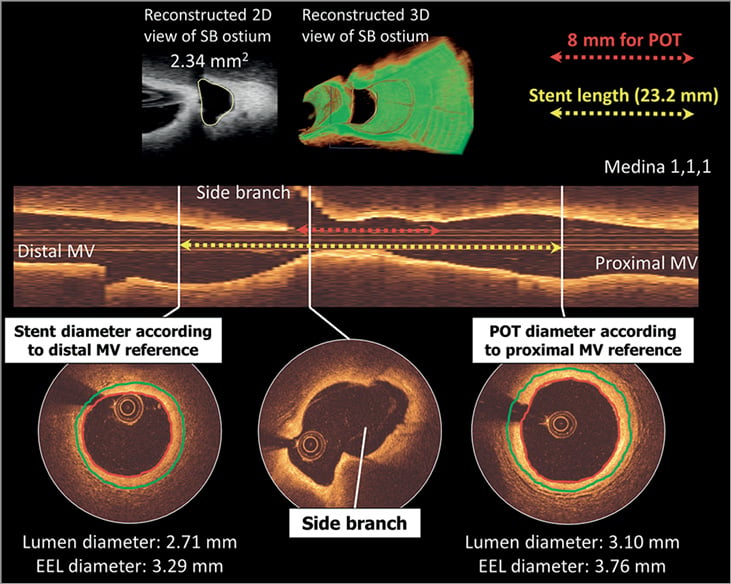
Figure 4. Lumen-based or EEL-based guidance for stent sizing. A distal RCA bifurcation with distal and proximal reference cross-sections is shown. According to the lumen-based stent sizing used in the OPINION trial, the lumen-guided stent diameter is calculated as 2.75 mm (0–0.25 mm greater than the lumen diameter at the distal reference site). On the other hand, the smallest EEL diameter from both distal and proximal reference segments is 3.29 mm (distal reference). According to EEL-based sizing used in the ILUMIEN III trial, this was rounded down to the nearest 0.25 mm and thus a 3.25 mm diameter stent will be chosen. Stent length was decided as 24 mm by measuring the distance from the distal to the proximal reference site (yellow arrow). The operator should aim to cover the bifurcation stenosis segment at least 8 mm from the proximal stent edge to the bifurcation carina (red arrow) considering the available length of the balloon for POT. EEL: external elastic lamina; MV: main vessel; POT: proximal optimisation technique; RCA: right coronary artery
– The size of stent should be selected aiming at the fractal geometry of bifurcation according to the law of flow conservation. The MV stent should be sized according to the distal MV reference diameter, whereas the MV stent should allow for expansion to the reference diameter of the proximal MV2.
LENGTH AND POSITIONING OF STENT IN BIFURCATIONS
In terms of stent length evaluation on OCT, the operator should aim to cover the bifurcation stenosis segment at least 6-8 mm from the proximal stent edge to the bifurcation carina, to enable the appropriate proximal optimisation technique (POT) with the shortest available balloon when indicated (Figure 4)2. POT is currently recommended just after implanting the stent with the distal MV diameter, whatever complementary technique may be used. In bench testing it was demonstrated that POT significantly reduced SB ostium strut obstruction, from 34.0% to 26.0%, concomitantly increasing the distal cell area ratio from 22.1% to 28.7% (p<0.05)43. As mentioned above, use of co-registration of OCT and angiography should facilitate the execution of precise stent positioning according to OCT findings.
– As far as the stent length is concerned on OCT, the operator should aim to cover the bifurcation stenosis segment at least 6-8 mm from the proximal stent edge to the bifurcation carina to enable subsequent POT with a short balloon.
DECISION MAKING ON STENTING STRATEGY USING OCT
According to the latest EBC recommendation6, the provisional SB stenting strategy is considered the “standard” approach for treatment of the vast majority of bifurcation lesions. Upfront use of two stents may basically only be needed in very complex lesions with large calcified side branches with ostial disease extending >5 mm from the carina and in bifurcations with side branches whose access is particularly challenging and where the SB should be secured by stenting once accessed.
Following this recommendation, OCT from the SB could be used to evaluate the distribution of the calcified lesion in the side branch. In the presence of a severe ostial lesion in the SB, blood clearance is sometimes incomplete for obtaining clear OCT images in the SB. Therefore, predilatation with a small balloon may be required.
GUIDANCE OF THE REWIRING IN A DISTAL CELL OF THE STENT OVERHANGING A SIDE BRANCH OSTIUM
After placing the stent in the bifurcation using either a one-stent or two-stent technique, kissing balloon inflations are used in order to form the stent in bifurcation fractal geometry2. To minimise the risk of struts being pushed inside the MV by kissing balloon inflation by creating a so-called de novo “metal carina” in the MV, it is important to rewire in the distal cell of the jailed side branch ostium (Figure 5)2. The protrusion of the metal carina into the MV is determined mainly by the recrossing point. In general, distal recrossing promotes a better ostial side branch stent coverage and apposition, while proximal recrossing results in unusual strut deflection, a lower strut coverage of the side branch ostium and more overhanging metal into the SB, resulting in a high shear rate region at the overhanging struts and a low shear rate behind them (Figure 5)44.
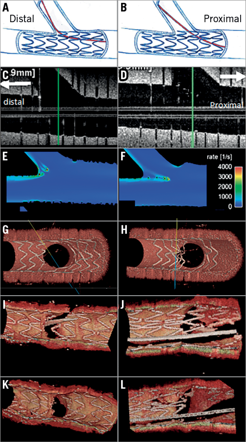
Figure 5. Impact of the rewiring position and strut malapposition in bifurcation. Left column (A, C, E, G, I and K) and right column (B, D, F, H, J, L) show distal rewiring and proximal rewiring, respectively. Panels C and D are longitudinal OFDI images. The computational flow simulation of the shear rate is shown in panels E and F. Panels G and H show the 3D reconstruction of struts in phantom. Panels I and J indicate the wiring position in 3D OCT in human coronary bifurcation before kissing balloon dilatation (KBD), whereas panels K and L are 3D reconstruction images after KBD.
The optimal position of wire recrossing after MV stenting is influenced not only by the distal position of the wire but also by the stent design and configuration of jailing struts45,46. The presence of a longitudinal link between the rings in front of the ostium was associated with more frequent malapposition compared to the cases without a longitudinal link (Supplementary Figure 2).
Taking into account the design of stent, the presence or absence of a strut link in front of the ostium and the distal positioning of the recrossing wire, the proposed optimal wire position is presented in Figure 6 (modified from Okamura et al45). In principle, the optimal recrossing point is in the distal compartment delineated by the bifurcation carina (yellow in Figure 6, panels A, A’) and the most distal ring of the stent within the bifurcation. When the most distal stent ring is in contact with the rim of the carina (Figure 6, panels B, B’), a second distal compartment is considered the optimal cell to be recrossed with a wire. In the presence of multiple second distal compartments (Figure 6, panels C, C’), a larger compartment should be selected.
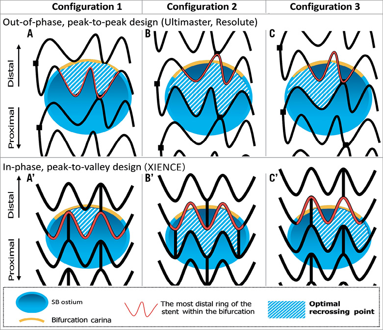
Figure 6. Optimal recrossing point in the side branch ostium according to different configurations of overhanging struts. The upper row depicts struts with out-of-phase, peak-to-peak design placed on the side branch ostium. The lower row depicts struts with in-phase, peak-to-valley design placed on the side branch ostium. In principle, the optimal recrossing point is in the distal compartment delineated by the bifurcation carina (yellow line) and the most distal ring of the stent within the bifurcation (red strut) (configuration 1: A and A’). When the most distal stent ring is in contact with the rim of the carina (configuration 2: B and B’), a second distal compartment is considered as the optimal cell to be recrossed with a wire. In the presence of multiple second distal compartments (configuration 3: C and C’), a larger compartment should be selected.
The feasibility of OCT guidance in selecting the recrossing point (with either 2D or 3D images) and its potential benefit have been assessed in a few studies (Supplementary Table 1). Alegria-Barrero et al47 reported that, in 52 patients undergoing elective treatment of bifurcation lesions using provisional stenting as the default strategy, lesions that were recrossed with OCT guidance (n=12) had a significantly lower number of malapposed stent struts, especially in the quadrants towards the SB ostium (9.5% [7.5-17.4] in the OCT-guided group vs. 42.3% [31.2-54.7] in the angiography-guided group, p<0.0001). In this study, OCT guidance was based mainly on 2D cross-sections. In a prospective registry with 3D OCT acquisition in bifurcation, Okamura et al demonstrated that the feasibility of assessment of the guidewire recrossing point after MV stenting was 89.9% (Figure 7)45,48,49. However, the evidence stemming from these two studies is limited to mechanistic observation.

Figure 7. Confirmation of the recrossing position of the wire after stent implantation by 3D OCT image. A metallic stent (Nobori 3.5/18 mm; Terumo) was implanted from the LM to LAD crossing over the LCx. OCT was performed after wire recrossing. 3D OCT images revealed that the position of the wire was located in the proximal cell (A). After a second attempt at rewiring, the distal recrossing was confirmed by 3D OCT (B). No malapposed struts were observed after KBD (C). Coronary angiography after KBD is shown in panel D.
While randomised trials such as DOCTOR Recross, OCTOBER and OPTIMUM (Supplementary Table 2) are ongoing to investigate the clinical benefit of online 3D OCT guidance in bifurcation treatment, it is recommended that 3D OCT imaging on the recrossing position after main vessel stenting is performed before final kissing balloon, to ensure the optimal position of the wire. The repeated 3D OCT imaging should be performed cautiously taking into account the cumulative amount of contrast agent.
– Prior to kissing balloon after stenting, it is important to recross the side branch ostium strut cell with a wire in the most distal cell to minimise the risk of pushing struts towards the MV.
– Use of OCT is recommended to exclude accidental abluminal rewiring and to assess the position of the recrossing wire. On 3D OCT, the optimal recrossing point is in the distal compartment without compromising the bifurcation carina (Figure 6). When the wiring position is not optimal, repositioning of the wire may be considered (Figure 7).
POST-PROCEDURAL ASSESSMENT (STENT EXPANSION, DISSECTION, MALAPPOSITION, TISSUE PROTRUSION, SIDE BRANCH OSTIUM)
After PCI in a bifurcation, OCT is used to evaluate stent underexpansion, malapposition, tissue protrusion, dissection, geographic miss and thrombus50. Stent expansion is evaluated either as an absolute measurement of the minimum stent cross-sectional area or as a relative expansion compared with the predefined reference area. In a bifurcation, considering its fractal anatomy, stent expansion should be evaluated separately in the proximal MV, distal MV and SB, with respect to each reference area51. Larger stent expansion is generally associated with better clinical outcomes. It has been demonstrated that stent malapposition is more common at the proximal MV and tissue prolapse or dissection at the distal MV segment. In addition, previous studies have demonstrated the feasibility of 3D OCT for correction of eccentricity in the ostium area of the side branch3,15,52-54. In patients with complex bifurcation stenosis undergoing PCI with a dedicated bifurcation system, FKBI is associated with improved anatomical and functional results at the SB ostium, without compromising the result at the MB55.
In general, a small edge dissection found on OCT which is undetected on angiography most likely does not have a clinical impact56-59. However, the following factors need to be considered: the longitudinal (≥3 mm) and circumferential extension (≥60 degrees) of the dissection, the intra-dissection lumen area respective to the reference (<90%) and the depth of the dissection (media or even adventitia). In ILUMIEN III, edge dissections were categorised as major if they constituted ≥60 degrees of the circumference of the vessel at the site of dissection and/or were ≥3 mm in length. In that trial, when the intra-dissection lumen area was <90% of the respective reference area, additional stent implantation was considered. In the CLI-OPCI II trial, dissection was defined on OCT as a linear rim of tissue with a width of ≥0.2 mm and a clear separation from the vessel wall or underlying plaque. In this retrospective multicentre registry, the acute dissection in the distal stent edge was an independent predictor of major adverse cardiac events60.
So far, no specific study on bifurcation is available covering this aspect. If the malapposition distance from the endoluminal lining of the strut to the vessel wall is <250 µm, such struts are likely to come into contact with the vessel wall at follow-up. Therefore, such small malapposition may be less relevant61-63. The clinical relevance of acute malapposition on stent failure has not yet been fully established60,64-66. Acute strut malapposition could persist (persistent malapposition) or resolve at follow-up (resolved malapposition), whereas strut malapposition could also develop during follow-up (late acquired malapposition). The temporal evolution and disappearance of malapposition has made the investigation of the clinical relevance of strut malapposition more complicated.
– The proximal MV is predisposed to more frequent malapposition whereas the distal MV is predisposed to more frequent tissue prolapse.
– Acute incomplete stent apposition with a distance of ≤300 microns is likely to be resolved at follow-up. Additional post-dilatation is considered when the malapposition distance is >300 microns with a longitudinal extension ≥1 mm.
– Most edge dissection detected on OCT is clinically silent, whereas additional stenting may be performed if the width of the distal edge dissection is ≥200 microns60.
LEFT MAIN BIFURCATION
Acquisition of OCT images in the left main (LM) trunk is challenging; documentation of the ostial region is in principle impossible due to cannulation of the guiding catheter beyond the ostium. Even if the guiding catheter is withdrawn from the ostium, image acquisition is difficult due to incomplete elimination of red blood cells in the aorta. In the current European guidelines for myocardial revascularisation, OCT is not considered for LM intervention, whereas IVUS is recommended as class IIa for this indication67.
Nevertheless, a few studies have demonstrated that frequency domain OCT for sizing in the non-ostial LM coronary artery is feasible68,69. In 54 patients with non-ostial LM disease, Burzotta et al demonstrated that 81% of frames were analysable and that the majority of non-analysable, artefact frames were in the proximal LM69. In the recent IDEAL-LM trial randomising XIENCE (Abbott Vascular, Santa Clara, CA, USA) and SYNERGY™ (Boston Scientific, Marlborough, MA, USA) stents in LM lesion PCI, post-implantation FD-OCT results were available in 91% of lesions.
In a study by Fujino et al, post-procedure, malapposed struts were more frequently observed in the proximal segment of the LM treated with drug-eluting stents, compared to the distal segment. At nine months, malapposition and uncovered struts were also more frequently observed in the proximal segment70. Taking into account the physiological significance of overhanging struts in front of the circumflex ostium or LAD ostium, the importance of 3D OCT guidance for the recrossing point through the cell strut is also emphasised in LM stenting (Figure 7). In the randomised EXCEL trial, acute LM stent deformation assessed by IVUS was most frequently observed in the LM ostium (5.4%) and was associated with a higher lesion failure (HR 2.15, 95% CI: 1.05, 4.40, p=0.04). On OCT, longitudinal measurement as well as 3D reconstruction is useful to detect the longitudinal deformation, although OCT is limited in the assessment of an ostial lesion.
In post-procedural evaluation, an IVUS study suggested certain cut-offs for minimal lumen areas after left main stenting71. Similar cut-offs using OCT still need to be validated; however, considering that OCT provides slightly smaller yet comparable corresponding measures, the values may safely be applied with OCT as well9.
– In interventions of non-ostial LM disease, OCT guidance is feasible and may be considered as long as the proximal stent edge is not covering the LM ostium.
OCT TO EVALUATE BIFURCATION-DEDICATED STENTS AND NEW TECHNOLOGIES
OCT has also been used to assess the procedural success of new bifurcation stenting technologies and bioresorbable scaffolds (Supplementary Appendix 2-Supplementary Appendix 7, Supplementary Figure 3-Supplementary Figure 5). Most case reports visualise the complex anatomical structure of bifurcation-dedicated stents in 3D OCT (Supplementary Table 6). There are also several studies reported (Supplementary Table 7) or ongoing (Supplementary Table 8) with endpoints defined by OCT measurements.
– OCT is used to assess the acute and chronic efficacy of a dedicated bifurcation stent system. 3D OCT facilitates the understanding of the device structures in vivo.
Conclusion
This consensus document is based on expert opinion of the members of the European Bifurcation Club and Japanese Bifurcation Club on the usage of OCT in coronary bifurcation PCI. With recent technical and technological advances, it is feasible to use OCT in guiding complex procedures in bifurcations. Although the recent clinical evidence starts to support OCT guidance, dedicated evidence for bifurcation treatment is still warranted. This document should be updated and expanded in the future according to the upcoming clinical evidence stemming from ongoing trials and investigations.
Appendix
Contributors: Pascal Motreff, MD, PhD, Cardiology Department, CHU Clermont-Ferrand, Clermont-Ferrand, France; Cardio Vascular Interventional Therapy and Imaging (CaVITI), Image Science for Interventional Techniques (ISIT), UMR CNRS 6284, Auvergne University, Clermont-Ferrand, France; Ricardo A. Costa, MD, PhD, Instituto Dante Pazzanese de Cardiologia, São Paulo, Brazil; Gérard Finet, MD, Hôpital Cardiologique, Claude Bernard University, Lyon, France; Yusuke Fujino, MD, PhD, Department of Cardiology, New Tokyo Hospital, Chiba, Japan; Juan Luis Gutiérrez-Chico, MD, PhD, FESC, FACC, Department of Interventional Cardiology, Charité University Hospital, Campus Benjamin Franklin, Berlin, Germany; Indulis Kumsars, MD, Latvian Center of Cardiology, Paul Stradins Clinical Hospital, Riga, Latvia; Massoud A. Leesar, MD, Division of Cardiovascular Diseases, University of Cincinnati, Cincinnati, OH, USA; Jacek Legutko, MD, PhD, Institute of Cardiology, Jagiellonian University Medical College, Krakow, Poland; Jasvindar Singh, MD, Division of Cardiology, Department of Medicine, Washington University School of Medicine, St. Louis, MO, USA; Yoshinobu Murasato, MD, Kyushu Medical Center, Fukuoka, Japan; Junya Shite, MD, PhD, Department of Cardiology, Osaka Saiseikai Nakatsu Hospital, Osaka, Japan; Yutaka Hikichi, MD, Saga University School of Medicine, Saga, Japan.
Guest Editor
This paper was guest edited by Adnan Kastrati, MD; Deutsches Herzzentrum München, Munich, Germany.
Conflict of interest statement
Y. Onuma is a member of the Advisory Board of Abbott Vascular. F. Burzotta has received speaker’s fees from Abbott/St. Jude in relation to talks on OCT use. N. Holm reports grants and personal fees from Abbott, personal fees from Terumo, grants and personal fees from Boston Scientific, and grants from Medis medical imaging systems. N. Amabile reports honoraria and/or consulting/lecture fees from Boston Scientific and Abbott Vascular. G. Mintz reports fellowship and/or research support from Boston Scientific, Abbott and Philips, and honoraria and/or consulting/lecture fees from Boston Scientific, Philips and Infraredx. T. Lefèvre reports fees from Abbott Vascular. P. Motreff has served as a consultant for Terumo and Abbott. J. Legutko reports lecture fees from Terumo and Abbott. J. Singh has served as a consultant/speaker for Abbott and Philips/Volcano. J. Shite reports lecture honoraria from Abbott and Terumo. P.W. Serruys is a member of the Advisory Board of Abbott Vascular. The other authors have no conflicts of interest to declare. The Guest Editor has no conflicts of interest to declare.
The references can be found in the online version of this article.
Supplementary data
Supplementary Appendix 1. OCT in comparison to QCA and IVUS.
Supplementary Appendix 2. OCT to evaluate bifurcation-dedicated stents.
Supplementary Appendix 3. OCT for bioresorbable scaffolds.
Supplementary Appendix 4. Polymeric bioresorbable scaffolds.
Supplementary Appendix 5. Magnesium scaffold.
Supplementary Appendix 6. OCT in bench testing and preclinical study.
Supplementary Appendix 7. Flow-velocity and pressure simulation in bifurcations using OCT and 3D angiography.
Supplementary Figure 1. Carina shift in the distal right coronary artery visualised on 3D OCT.
Supplementary Figure 2. Configurations of overhanging struts in front of the side branch ostium and the results of KBD.
Supplementary Figure 3. Hybrid treatment of bifurcation lesions with BVS and metallic stents.
Supplementary Figure 4. The jailed side branch with the number of compartments created by the criss-cross of the struts as well as the configuration of the jailing struts.
Supplementary Figure 5. Serial assessment of jailed side branch over five years.
Supplementary Table 1. Published clinical studies on OCT-guided PCI in bifurcations.
Supplementary Table 2. Randomised controlled trials of OCT versus angiography-guided or IVUS-guided drug-eluting stent implantation with or without bifurcation lesions.
Supplementary Table 3. Comparison of IVUS versus OCT in bifurcation treatment.
Supplementary Table 4. OCT acquisition in bifurcations. Tips and tricks.
Supplementary Table 5. Clinical studies with qualitative or quantitative endpoints using 3D OCT.
Supplementary Table 6. Case reports of bifurcation-dedicated stents with OCT evaluation.
Supplementary Table 7. Clinical studies of bifurcation-dedicated stents with OCT evaluation.
Supplementary Table 8. Ongoing device trials in bifurcation using OCT.
To read the full content of this article, please download the PDF.