Abstract
Treatment of bifurcation lesions by percutaneous coronary intervention (PCI) shows major variation in complexity. Intravascular optical coherence tomography (OCT) provides high-resolution images of the pathoanatomy, thrombus, wires and stent positions during the procedure. This information may prove crucial in optimising PCI results and clinical outcomes after complex bifurcation treatment. Mounting evidence confirms the feasibility of OCT in bifurcations, and specific steps where OCT may be advantageous in guiding bifurcation PCI have been identified. Awaiting major clinical outcome trials, OCT has already entered the European guidelines for myocardial revascularisation. This paper aims to provide an overview of the potential clinical use of OCT in bifurcations.
Introduction
Intravascular optical coherence tomography (OCT) is the most promising adjunctive imaging tool for guiding coronary bifurcation intervention1-3. Entering the European guidelines on myocardial revascularisation4, the dissemination and use of OCT are increasing rapidly. Excellent clinical results are achieved using simple crossover stenting in most bifurcation lesions5-7. With the increasing complexity of lesions and treatment, inadequate angiographic control of procedural steps may have increasing impact. Despite various stent enhancement modalities, angiography has limited capacity for showing vessel wall features, luminal masses, stent struts and wire positions. OCT provides this information in high-resolution cross-sectional images8 and three-dimensional (3D) reconstructions9-11. Here we present an overview of the potential clinical use of OCT in bifurcations.
OCT acquisition in bifurcations
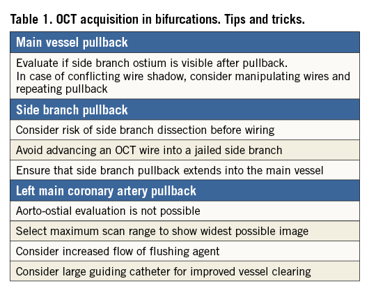
Acquiring OCT pullbacks in bifurcations is associated with specific challenges. In addition to inadequate flushing of the vessel, guidewire shadows can cover a side branch (SB) ostium partially or entirely. Careful evaluation of the pullback immediately after acquisition may ensure that the required information (e.g., SB ostium) is recorded (Table 1). Manipulating the guidewire and repeating the pullback may be required to obtain essential information. Acquisition in the SB may be of value in complex bifurcation stenting12. Care should be taken when advancing the rather stiff OCT catheter into an angulated SB after balloon dilatation but before potential stenting, as this manoeuvre might increase the risk of worsening dissections inflicted by the SB dilatation. Re-crossing into a jailed SB with the OCT catheter should be avoided as it might cause distortion of the main vessel (MV) stent or the catheter could get entrapped or damaged. When positioning the OCT catheter in the SB, ensure that the pullback extends into the MV for full evaluation of the SB ostium.
Assessment of wire positions in SB re-crossing, detection of strut fracture and the quality of 3D renderings may be aided by pullbacks with high longitudinal resolution as enabled with latest-generation OCT systems13. This should be balanced against the increased contrast use and more frequent cardiac motion artefacts seen at lower acquisition speeds14. Left main coronary artery (LMCA) acquisition is feasible except for the evaluation of the aortic ostium15, though adequate clearing of the lumen may require a higher flow of contrast during acquisition16. Ensuring that the maximum scan range is displayed on screen, OCT is able to show the entire lumen wall in most midshaft and distal LMCA lesions needing treatment15.
Methods for evaluation of the SB ostium
The correct estimation of the size of the SB ostium is important in the evaluation of bifurcation stent techniques and devices. It is thought to be useful for selecting the size of balloons and stents, and is accordingly expected to be of clinical importance17. For the most accurate assessment of the ostial area (including minimal, maximal and mean diameter), it is suggested that OCT pullbacks should be obtained from both the MV and the SB. In clinical practice, this may be challenging from a safety and feasibility point of view, and therefore ostial measurements are often estimated from one MV pullback alone. Thus far, several approaches have been proposed for this, ranging from measurements in two-dimensional (2D) single/multiple cross-sections, to more complex 3D renderings.
2D ostial measurements
Measuring the SB from a single cross-section is performed by selecting a cross-section with a well visible SB at the carina point and measuring the area and diameters18 (Figure 1A). This method is straightforward, but the results are highly dependent on the SB angulation and carry a high risk of missing smaller areas and diameters in more ostial positions in non-perpendicular planes. The measurements may result in overestimation of the largest diameter and area. Furthermore, the SB may be only partly visible due to the limited penetration depth of OCT, and the method is not applicable in SBs with around a 90 degree offspring. The SB might also be assessed from the longitudinal view, but in current OCT systems only rulers parallel to the imaging catheter are available, thereby limiting the precision. The measurement is very sensitive to the shape and angulation of the ostium, and only SBs with 90 degree offspring and round-shaped ostia may be assessed reliably this way (Figure 1B). Measuring the SB from multiple cross-sections can be performed in at least two ways. 1) The area of the oval opening of the SB is estimated by counting the number of cross-sections where the SB is visible multiplied by the thickness of cross-sections multiplied by the diameter of the largest opening of the SB multiplied by 1/4π19 (Figure 1C). The drawback is that the ostium plane is parallel to the imaging wire and not necessarily perpendicular to the SB, again resulting in overestimation of the largest diameter and area of the ostium. 2) The ostial area is assessed by measuring the width of the SB opening in all cross-sections where visible. The widths are added together and subsequently multiplied by the distance between cross-sections (Figure 1D). The advantage is that the ostium plane can be defined perpendicular to the SB vessel. The disadvantage is cumbersome measuring of width in all cross-sections where the ostium is visible.
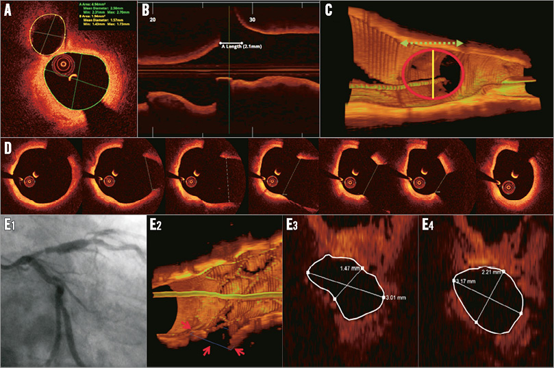
Figure 1. Five methods of measuring the area of the side branch ostium from a main vessel pullback. A) Tracing the SB in the cross-sectional image at the carina position. B) Measuring the length of the SB ostium in the longitudinal view and calculating the area as π * (1/2 * diameter)2. C) Counting the number of cross-sections where the SB is visible multiplied by the thickness of cross-sections multiplied by the diameter of the largest opening of the SB multiplied by 1/4π19. D) Measuring the width of the SB opening in all cross-sections where visible. The widths are added together and subsequently multiplied by the distance between cross-sections. E) 3D adjusted 2D measurement plane with manual detection of the minimal luminal area (Cut Plane, QAngioOCT RE; Medis).
3D ostial measurements
To overcome the limitations of the 2D techniques, Tu et al proposed a 3D rendering technique in which a volume is created from the pullback18. The technology (Cut Plane, QAngioOCT RE; Medis, Leiden, The Netherlands) was found to provide more accurate assessments of the SB ostial area compared to 2D ostial measurements by MV OCT pullbacks21. The user can interactively select a viewing plane perpendicular to the SB or manually fit the plane to obtain the smallest ostial area. In this resulting cut plane the measurements can be performed (Figure 1E). The advantage is that the cut plane can be perpendicular to the SB, but the 3D information is based on a straight vessel reconstruction, which is not the actual 3D situation. Furthermore, the method still depends on the visibility of the SB, and the cut plane selection is manual.
Stent cell measurements
Stent cell parameters covering an SB may also be determined. This can be done in 2D projections perpendicular to the imaging wire11,19 or by indicating the individual strut points and taking their 3D positions into account to calculate the actual cell areas21. These measurements are combined with the ostial measurements to determine the coverage of a side branch19. Limitations of measurements utilising 3D information include their sensitivity to the regularity of the 3D pullback information. This regularity is affected by bending of the OCT imaging wire, guidewire shadows and cardiac motion artefacts11.
Treatment strategy guided by OCT
LESION DISTRIBUTION
Atherosclerotic lesions tend to form at specific regions with low shear stress. Therefore, coronary bifurcations are extraordinarily susceptible to atherosclerosis. Pathological studies have demonstrated that, at bifurcations, the lateral wall (opposite the flow divider) rather than the flow divider itself showed significantly greater intima proliferation and necrotic core formation22. In vivo OCT analysis reported similar observations. Lipid accumulation tends to develop in regions opposite the SB in the MV, and thin-cap fibroatheroma (TCFA) is localised predominantly in the region opposite the flow divider, whereas the flow divider itself is rarely affected23. This particular predilection for distribution of atherosclerotic disease should be recognised when assessing the risk of SB compromise following MV intervention. Online Figure 1 shows a representative plaque distribution at the bifurcation lesion in a patient with acute coronary syndrome.
OCT PREDICTORS OF SB COMPROMISE
SB occlusion is a serious complication after MB stent placement, and important work has been carried out to identify predictors of SB compromise. Angiographic predictors of SB compromise include diameter stenosis >50% at the SB and proximal MV24. By intravascular ultrasound (IVUS) analysis, it was shown that larger plaque burden proximal to the SB offspring25 , lower lumen volume index, SB minimal luminal area and larger plaque burden at the distal MV26 were associated with SB compromise, whereas Kang et al found that there was no association between the MV plaque distribution and SB compromise27. Although derived from IVUS, OCT enables the same evaluation in the presence of fibrocalcific plaques, whereas lipid plaques most often preclude adequate plaque volume estimations. Eccentric plaque oriented towards the opposite side of the SB (Online Figure 1) may increase the risk of carina shift after MB stenting28. A recent OCT study suggested that a narrow bifurcation angle, a narrow carina tip angle and the diameter of the SB orifice were related to SB compromise after MB stenting28 (Figure 2).
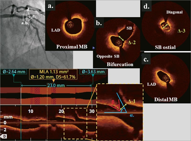
Figure 2. A 72-year-old male with stable angina pectoris. Angiogram showed a Medina 0,1,1 lesion at the LAD/diagonal bifurcation. At the bifurcation core segment, eccentric plaque was located opposite the SB. The diameter of the SB orifice can be measured by MV OCT pullback image (∆–1, ∆–2) or SB pullback (∆–3). Αlpha indicates SB angle and β indicates the carina tip angle.
SIZING AND POSITIONING OF STENTS IN BIFURCATIONS
OCT may be used to identify proximal and distal, minimally diseased, reference segments for direct estimation of the reference size, or to confirm that reference segments as suggested by angiography were appropriate. In diffuse disease, reference size estimation may integrate luminal measurements and vessel size. The vessel size is assessed by identifying and contouring the media layer in cross-sections with limited lipid plaque formation. The stent diameter should be adjusted according to the distal reference segment to avoid overdilating smaller vessels distal to the bifurcation site (Online Figure 2)29. Stent length estimation should aim to cover the narrowed segment, if possible, allowing at least 8 mm from the proximal stent edge to the carina to accommodate the proximal optimisation technique (POT) if indicated29.
OCT after stent deployment
WIRE RE-CROSS IN PROVISIONAL SIDE BRANCH STENTING TECHNIQUE
The position of the wire re-crossing into the SB influences scaffolding of the ostium30-32. Rewiring through a distal stent cell ensures a short or no metallic carina and stent coverage of the proximal part of the ostium of the SB. Thus, compared to proximal rewiring, a distal position reduces malapposition and the amount of jailing struts or carinal struts at the bifurcation core segment. OCT enables detailed evaluation of the wire position10, and strategies for repositioning of the wire are proposed. On-line 3D OCT may be of particular value in identifying the stent cell after rewiring the SB33. OCT evaluation of the wire position is also useful when balloons cannot be advanced into a jailed SB. Often, a very eccentric wire position is identified (Online Figure 3) or the SB wire has been passed at the abluminal side of the stent in the proximal segment.
WIRE RE-CROSS IN DOUBLE STENTING
The position of SB wire re-crossing may also be important in two-stent techniques34. A distal wire position may lead to a reduction in metallic carina formation and improved scaffolding of the ostium, but pursuing a very distal strut position might increase the risk of abluminal rewiring of the SB stent35. SB dilatation following abluminal rewiring will crush the SB stent, most often partially due to the wire re-entering the true lumen more distally. In two-stent techniques, especially the crush technique without the double kiss modification, OCT may also reveal if the wire is positioned in a very narrow strut opening of double stent layers obstructing advancement of balloons (Moving image 1).
Lumen size and stent strut apposition
Underexpansion of stented segments is associated with in-stent restenosis36,37, and suboptimal stent results are frequent after angiographically guided bifurcation treatment38. Current clinical OCT systems provide efficient tools to check for underexpanded lumen and stents3. When the lumen is well expanded, it is unknown to what degree acute stent strut malapposition affects the prognosis. Neointimal coverage of malapposed struts is slower than in apposed struts39. Thus, full coverage may be achieved at a later time point, potentially limiting the safety of early discontinuation of dual antiplatelet therapy. The inherent risk of stent underexpansion and malapposition in the proximal MV may be reduced by POT40. The clinical importance of POT and potential downsides remain unknown. OCT can be used to assess the potential need for POT and to assess the optimal length and diameter of the balloon needed.
Accidental rewiring between stent and lumen
Clinical outcome in patients with jailed SB is comparable to the prognosis for non-bifurcation lesions41. This may limit the need for kissing balloon dilatation if SB TIMI flow grade 3 is maintained after MV stenting42. When KBI is indicated, there is a certain risk of erroneously advancing the second wire on the abluminal side of the proximal MV stent. This may result in unintended crush of the stent during balloon inflation, and may be prevented by prior post-dilatation of the proximal MV (POT)43. Moreover, abluminal rewiring of an SB stent detected using OCT may be crucial to correct before balloon dilatation. Still, there is a small risk that abluminal wiring of the SB stent remains undetected by MV OCT. Therefore, it is important to perform a post-intervention pullback to assess the final result, including evaluation of the lumen, stent expansion and strut apposition.
Left main bifurcation
The current European guidelines provide a class IIA recommendation for using IVUS to guide left main (LM) intervention, and OCT is at present not considered for this lesion subset4. IVUS allows assessment of the LM ostium as well as the delineation of the media in diffusely diseased vessels. In comparison, OCT imaging of luminal contours is feasible in most midshaft and distal LM bifurcations15,16, although aorto-ostial lesions are generally not assessable due to the need to engage the guiding catheter in the ostium to achieve proper flush. OCT is therefore unsuitable for interventions where visualisation of the LM ostium is crucial or where the vessel size exceeds the scan range of OCT –in our experience about 10% of cases. On the other hand, OCT provides superior imaging of calcifications, wire position and stent strut apposition, while using an imaging catheter with a smaller crossing profile.
With respect to evaluating the result of LM intervention, target cut-offs for minimal lumen areas assessed by IVUS have been suggested previously44. Similar cut-offs using OCT still need to be validated; however, considering that OCT provides slightly smaller yet comparable corresponding measures, the values may safely be applied with OCT as well.
OCT in bifurcation stent thrombosis and in-stent restenosis
OCT has important clinical value in the assessment of cases of stent failure, including both stent thrombosis (ST) and in-stent restenosis (ISR)4. With the exception of cases with massive thrombus load and total or subtotal lumen narrowing, the nature of the problem is in most cases elucidated using OCT. In cases with clinical presentation indicative of stent failure and an inconclusive angiogram, OCT can detect in-stent thrombosis45 (Online Figure 4) and can be used to detect scaffold disruption in radiolucent bioresorbable scaffolds (BRS)46. In general, assessment with OCT may lead to the use of fewer additional stents in the treatment of stent thrombosis. In cases where malapposition, underexpansion or uncovered struts have been identified as the likely cause of stent thrombosis, corrective measures with thrombus aspiration and/or additional balloon dilatation are usually sufficient to ensure a good final result. In cases with excessive neointima hyperplasia or in-stent neoatherosclerosis as the dominant cause of stent failure, OCT may be used to guide lesion preparation. In some cases of early stent thrombosis, OCT reveals an optimal stent implantation result. The mechanism in such cases may be ineffective platelet inhibition or due to systemic disease like cancer or major infection. Using OCT in the assessment of stent thrombosis in a bifurcation segment, we arbitrarily propose five categories of problem as shown in Figure 3. In bifurcation lesions, the ostium of the SB is particularly prone to in-stent restenosis. Full OCT assessment of the bifurcation in stent failure should be attempted. In cases where only an MV pullback can be obtained (e.g., severe SB ostial stenosis or obstruction of the SB ostium by stent struts), important information on the SB ostium may be obtained from the MV pullback. Details on how well the ostium of the SB is scaffolded with struts, the presence of stent struts in front of the SB ostium, stent expansion and apposition of struts are important for guiding the subsequent interventional treatment process.
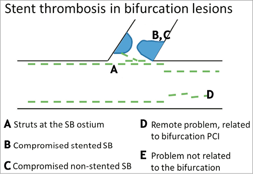
Figure 3. Schematic classification of causes of stent thrombosis in bifurcation lesions. A) Presence of stent struts at the core bifurcation segment. Permanent metallic struts or bioresorbable struts can present as: 1) jailing struts, 2) a metal neocarina where struts accumulate at the level of the bifurcation carina, or 3) non-apposed struts where struts have been manipulated and pushed into any other lumen position in the bifurcation core segment. B) Compromised stented side branch. This usually occurs due to underexpansion at the ostium of the SB, or because of an accumulation with different layers of stent struts leading to a delayed healing process leaving struts uncovered making them more prone to thrombus accumulation. C) Compromise of the non-stented SB, usually due to plaque shift or carina shift or plaque overgrowth. D) Problem remote from the core bifurcation segment, but related to the specific character of bifurcation PCI, e.g., problems due to double or triple layers of struts in the proximal main vessel or problems due to more extensive manipulation of stents in bifurcation PCI, such as damage to the polymer or mechanical integrity of the stent. E) The problem is not related to the bifurcation.
OCT for guiding PLLA-type bioresorbable scaffold implantation
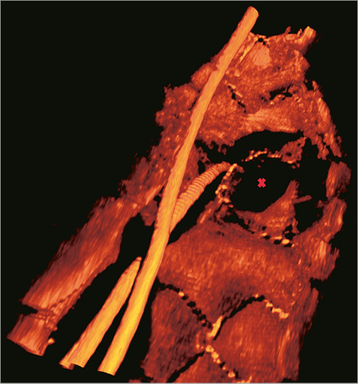
Intracoronary imaging is essential to assess BRS in bifurcation treatment since current BRS are: 1) radiolucent; and 2) made from poly-L-lactic acid (PLLA) that is more fragile and less deformable than the platform in permanent metallic stents. The clinical impact of adverse OCT findings using BRS, including stent strut malapposition (Online Figure 5A) or strut fractures detected in bifurcation treatment, is largely unknown47,48. Frequently seen signal-rich areas (scattering centres) in strut connections of the Absorb stent (Abbott Vascular, Santa Clara, CA, USA) have been identified as polymer crazing and this was not associated with strut fracture49 (Online Figure 5B). The in vivo 3D OCT appearance of current BRS may facilitate spatial perception of strut positions during bifurcation treatment (Online Figure 5C) compared to 2D images (Online Figure 5D).
Guiding BRS implantation by OCT
PRE-BRS IMPLANTATION OCT
Several treatment steps are crucial when using the Absorb BVS in bifurcations. Heavy calcification and spiculating calcifications might preclude the use of Absorb BVS in any lesion subset50. The extent and conformation of calcium are readily detected by OCT. The crossing profile of the Absorb (1.4 mm) and the 150 µm DESolve (1.5 mm) (Elixir Medical, Sunnyvale, CA, USA) mandates adequate predilatation of both the proximal and distal MV to be able to deliver the BRS. OCT can be used to evaluate the lumen after predilatation to assess whether the device may be successfully advanced (Online Figure 5D). Correct sizing using the Absorb is of paramount importance due to its limited expansion capacity beyond the nominal size51. OCT enables accurate reference size estimation of the proximal and distal references for the choice of appropriate diameter and length of the stent. Using DESolve, the higher expansion capacity might reduce the risk of fracture during upsizing of the proximal MV segment48. Still, the recommended maximum diameters stated in the instructions for use should be respected.
Post-BRS implantation OCT
BRS STRUT APPOSITION IN BIFURCATION TREATMENT
Strut apposition may be of particular importance using BRS. Thus, the high risk of malapposition in the proximal MV in bifurcations may indicate the use of POT and the use of OCT for sizing the POT balloon and subsequent evaluation of strut apposition. Cases of luminal degrading struts have been presented46 and, despite limited mechanistic insight, early strut coverage facilitated by carefully apposing struts52 and avoiding overlapping struts may be advantageous to ensure struts are encapsulated in the vessel wall when degrading.
STRUT FRACTURE USING BRS
BRS fracture represents a particular challenge in bifurcation treatment. Strut fracture and strut discontinuity can be detected by 2D OCT as: 1) overlapping struts where stents are not overlapping; or 2) abrupt strut discontinuity including struts protruding single-ended into the lumen46. High longitudinal resolution, high-quality, non-enhanced OCT renderings in 3D may become the standard for both in-procedure and core lab detection of strut fracture (Figure 4).
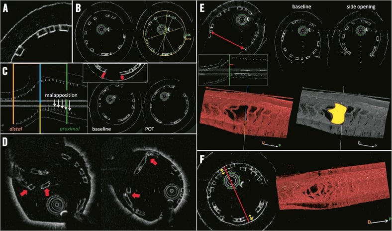
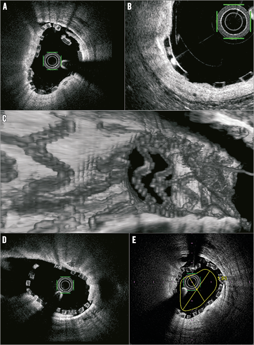
Figure 4. Optical frequency domain imaging of the Absorb Bioresorbable Vascular Scaffold (BVS) in a bench model. A) Black-box appearance of struts without shadowing. B) Measurements of lumen and BRS areas and diameters. C) Strut malapposition and impact of proximal optimisation technique (POT) on proximal apposition. D) Examples of BRS strut fractures. E) Assessment of side branch opening in cross-section, longitudinal view and in a 3D rendering; impact of side branch opening. F) Lumen obstruction in the proximal main branch treated with the culotte technique.
Wire re-cross using BRS
Bench tests have shown that dilatation of the SB by a 3.0 mm non-compliant balloon through an MV Absorb BVS did not cause strut fracture at deployment pressures up to 5 atm and up to 20 atm for DESolve BRS53. It is unknown if rewiring extreme stent cell positions in the ostium increases the risk of fracture (John Ormiston, communication at European Bifurcation Club Meeting 2014, Bordeaux, France). Thus OCT may be indicated to evaluate the actual wire position after SB re-crossing and before balloon inflation.
BRS obstruction
The thickness of present BRS struts (approximately 150 µm) and the slightly increased neointimal thickness at follow-up compared to permanent DES may lead to an early reduction in lumen area. Reports of late lumen enlargement are intriguing, but careful treatment may be needed to avoid early symptomatic restenosis using BRS. This is especially the case in small vessels, as SBs often are, and with overlapping stents as frequently used in complex bifurcation treatment. The present recommendation is to position BRS end-to-end guided by angiography50. This may translate into recommending only end-to-side application (T-stenting) in bifurcations to avoid overlap with present BRS. OCT may be used to check whether end-to-end or end-to-side positioning was successful or if an overlapping segment needs additional post-dilatation. The early resulting lumen after neointimal healing but before late lumen enlargement might be predicted by an artificial contour corresponding to a neointimal thickness of approximately 100-150 µm (Online Figure 5E).
Side branch BRS
Depending on the actual SB stenting technique or two-stent technique, OCT may be used to assess the degree of protrusion of an SB stent into the MV. If, in final OCT evaluation, the MV is jailed by the SB BRS, this may necessitate additional MV treatment. Using 150 µm thickness BRS, a careful check of the ostium in any two-stent technique may be important, as the resulting lumen after neointimal growth might be limited. Two-stent techniques using BRS are experimental, and at present only T-stenting and maybe T-and-protrude (TAP)54 in patients with highly appropriate anatomy might be of potential clinical value.
OCT in bench testing
Bifurcation stenting with BRS has been studied in various bench testing settings. Micro-computed tomography (micro-CT) is the gold standard for the evaluation of stents and stent techniques in bench testing (Figure 4). As presented at EBC 2014 by Pascal Motreff, OCT can be used for bench evaluation using translucent silicone phantoms yielding results almost comparable to micro-CT. Studying BRS requires mimicking in vivo conditions (fluid/water bath at 37 degrees Celsius). Owing to the feasibility of bifurcation bench testing evaluated by multi-step OCT, more researchers and interventional cardiologists may engage with this technology for research and training purposes.
Conclusion
The in vivo information obtained by OCT in bifurcations during PCI is unparalleled. While awaiting clinical outcome studies, OCT may be used for guiding complex PCI in bifurcation lesions. Further, multi-step OCT evaluation may be of particular importance using present-generation BRS for bifurcation treatment.
Conflict of interest statement
N.R. Holm has received institutional research grants and speaker’s fees from St. Jude Medical and Terumo. T. Adriaenssens has received a speaker’s fee from St. Jude Medical. E.H. Christiansen has received institutional research grants from St. Jude Medical and Terumo and speaker’s fees from St. Jude Medical. The other authors have no conflicts of interest to declare.
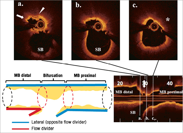
Online Figure 1. A 60-year-old male presented with non-ST-elevation myocardial infarction. Pre-intervention OCT revealed lipid-rich plaque accumulation opposite the ostium of a diagonal branch. Thin-cap fibroatheroma (TCFA) feature (asterisk), fibrous cap disruption (arrow) and thrombus attachment (arrowhead) were observed.
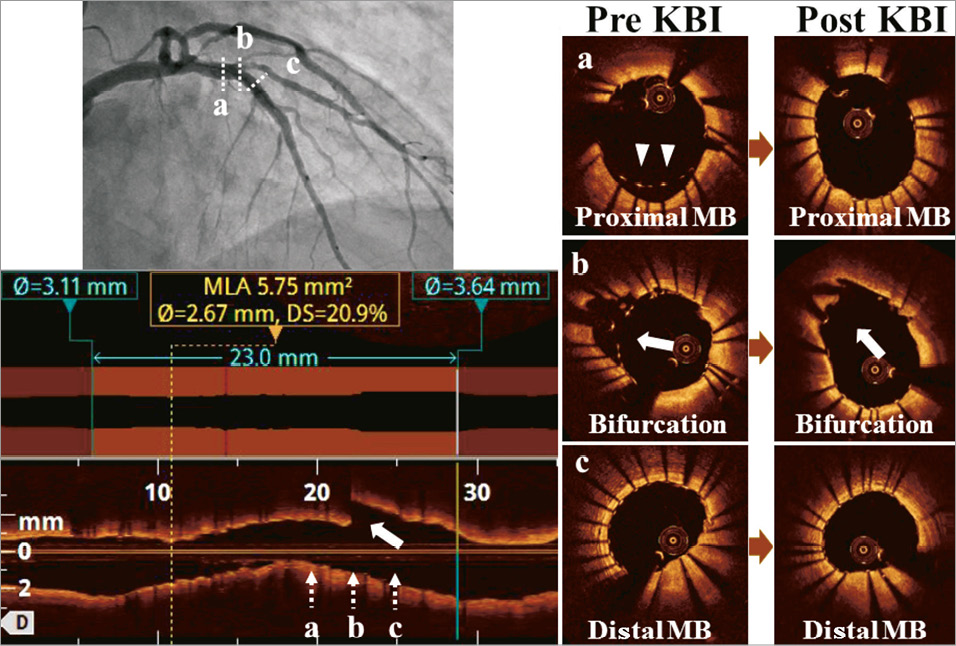
Online Figure 2. The patient in Figure 2 was treated with an everolimus-eluting stent (3.0*23 mm) since the mean lumen diameter of the distal reference was 2.64 mm and that of the proximal reference was 3.63 mm. OCT visualised incomplete strut apposition in the proximal MV (arrowheads) and jailed struts at the SB orifice (arrows). After kissing balloon inflation using 3.0 mm and 2.5 mm balloons, malapposition and jailed struts were adequately resolved with a final minimal lumen area of 5.75 mm2.
Online Figure 3. Crossover stenting with indication for SB intervention. After rewiring the SB, balloons could not be advanced. OCT revealed an eccentric wire position. After repositioning the guidewire, a balloon was successfully advanced (not shown).
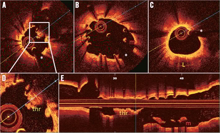
Online Figure 4. Main vessel OCT acquisition for stent thrombosis in a patient treated with T-stenting using drug-eluting stents 20 months earlier. A) Accumulation of thrombus (thr) around non-apposed struts at the level of the bifurcation (magnification in [D]). B) Malapposition (indicated with m), uncovered struts and some inter-strut cavities (between 7 and 8 o’clock) in the proximal main vessel. C) A zone of neoatherosclerosis (indicated with L) between 4 and 7 o’clock. E) Longitudinal view. The asterisk indicates the guidewire artefact. (Images provided by T. Adriaenssens, for the PRESTIGE investigators)
Online Figure 5. Main vessel OCT in bifurcation treatment using bioresorbable scaffolds (BRS). A) Malapposition is easily detected as separation between the abluminal side of the BRS strut and the vessel wall. B) Crazing is frequently seen as signal-rich spots in Absorb struts. This has been shown not to be a marker of strut disintegration. C) 3D OCT of side branch jailed by DESolve BRS. D) 2D OCT of the same side branch. E) Rough estimation of the early healing result after BRS implantation by adding an artificial lumen contour corresponding to an intimal layer of 150 µm. (Images from the DOCTOR Compare study)
Online data supplement
Moving image 1. Patient treated with the crush two-stent technique. After rewiring of the side branch through dual strut layers, balloons could not be advanced. OCT revealed that the side branch wire passed through a very narrow strut opening at the side branch ostium.
Supplementary data
To read the full content of this article, please download the PDF.
Patient treated with the crush two-stent technique. After rewiring of the side branch through dual strut layers, balloons could not be advanced. OCT revealed that the side branch wire passed through a very narrow strut opening at the side branch ostium.