Abstract
Aims: We describe three-dimensional optical coherence tomography (3D-OCT) guided bifurcation stenting and the clinical utility of 3D-OCT.
Methods and results: Twenty-two consecutive patients who underwent OCT examination to confirm the recrossing position after stent implantation in a bifurcation lesion were enrolled. Frequency domain OCT images were obtained to check the recrossing position and 3D reconstructions were performed off-line. The recrossing position was clearly visualised in 18/22 (81.8%) cases. In 13 cases, serial 3D-OCT could be assessed both before and after final kissing balloon post-dilation (FKBD). We divided these cases into two groups according to the presence of the link between hoops at the carina: free carina type (n=7) and connecting to carina type (n=6). All free carina types complied with the distal rewiring. The percentage of incomplete stent apposition (%ISA) of free carina type at the bifurcation segment after FKBD was significantly smaller than that of the connecting to carina type (0.7±0.9% vs. 12.2±6.5%, p=0.0074).
Conclusions: 3D-OCT confirmation of the recrossing into the jailed side branch is feasible during PCI and may help to achieve distal rewiring and favourable stent positioning against the side branch ostium, leading to reduction in ISA and potentially better clinical outcomes.
Abbreviations
2D: two-dimensional
3D: three-dimensional
ACT: activated clotting time
DES: drug-eluting stent
FD: frequency domain
FKBD: final kissing balloon post-dilation
ISA: incomplete stent apposition
MV: main vessel
OCT: optical coherence tomography
PCI: percutaneous coronary intervention
SB: side branch
Introduction
Bifurcation lesions represent 15-20% of all percutaneous coronary interventions (PCI)1. In the era of drug-eluting stents (DES), bifurcation treatment is one of the predictors of stent thrombosis2 and target lesion revascularisation3,4. Incomplete stent apposition (ISA) at the bifurcation segment can be a cause of these adverse sequelae5-9. The coronary guidewire recrossing position before final kissing balloon post-dilation (FKBD) is important to reduce the incidence of ISA10,11. Optical coherence tomography (OCT) can evaluate stent apposition more clearly than intravascular ultrasound (IVUS) due to its high resolution12. However, it is difficult to understand the spatial relationship between the stent and bifurcation structure only with cross-sectional OCT images. The in vivo appearance and pattern of the overhanging stent strut in front of the side branch (SB) ostium opened by the FKBD also remains speculative.
Three-dimensional (3D) reconstruction of OCT images is useful to assess the spatial aspect of bifurcation stenting13-17. We developed a novel off-line software for 3D stent imaging13 and tested the feasibility of 3D-OCT assessment of the recrossing position during the procedure. Moreover, the incidence of ISA after FKBD was assessed by OCT.
Methods
PATIENT POPULATION
All consecutive patients who underwent OCT examination to confirm the recrossing position after stent implantation in bifurcation lesions from September 2011 to July 2012 were enrolled in this study. The main exclusion criteria were <2 mm diameter of side branch (visual assessment), haemodynamic instability, renal insufficiency (serum creatinine ≥1.2 mg/dl or estimated GFR ≤50 mL/min/1.73 m2), and in-stent restenosis.
PROCEDURE
Patients received unfractionated heparin to maintain an activated clotting time (ACT) >250 sec, checked hourly. Procedures were performed using 6 or 7 Fr guiding catheters at the operator’s discretion. Predilatation of the main vessel (MV) was performed in all patients, whereas the SB was dilated before stenting only if there was flow compromise after MV predilatation. The stent was implanted in the MV across the SB. A jailed wire in the SB was maintained to straighten the SB origin and facilitate the identification of the SB ostium. A third wire was advanced into the distal MV with a small loop and then pulled back into the stent and advanced to the side branch in an attempt to recross the stent struts distal to the jailed SB wire, under fluoroscopic guidance.
OCT was performed after rewiring. If the position of the wire was not located in the most distal cell, further attempts to redirect the wire to a more distal cell were performed, with subsequent OCT acquisitions to confirm position in two-dimensional (2D) and off-line 3D reconstruction. FKBD was performed following the sequential dilatation if needed (not mandatory). When a second stent was required, the culotte technique was used18,19. After the second stent deployment, rewiring and OCT acquisition were repeated. OCT in the SB and MV were obtained after FKBD.
FD-OCT IMAGE ACQUISITION AND ANALYSIS
FD-OCT was performed using the ILUMIEN™ OCT imaging system (St. Jude Medical, Minneapolis, MN, USA) and C7 Dragonfly™ intravascular imaging catheter (St. Jude Medical). Automatic pullbacks were performed at 10 mm/sec during contrast injection at a setting of either 4 ml/sec, total 14 ml for LCA, or 3 ml/sec, total 10 ml for RCA, using a power injector. The C7 Dragonfly catheter was inserted distal to the MV stent and the pullback continued until either the guiding catheter was reached or the maximal pullback length (5.5 cm) was completed. OCT raw data were exported into the hard drive and transferred to the off-line workstation20. Automatic stent strut detection and enhancement was performed using the dedicated software. Images were exported as bitmap sequence files and imported into a volume-rendering software called INTAGE Realia (Cybernet, Tokyo, Japan).
Quantitative, off-line analysis of the OCT images was performed using proprietary computer software (St. Jude Medical). Frame-by-frame cross-sectional images were analysed by an experienced analyst, counting every single strut on each frame. Lumen area and stent area as well as strut malapposition were measured.
Incomplete stent apposition was defined as separation of at least one stent strut from the vessel wall. Struts were classified as ISA if the distance between the strut marker and the lumen contour was bigger than the specific strut thickness plus the axial resolution of OCT (14 μm)21. The cut-off points used for each stent type were: everolimus-eluting stent (XIENCE V®; Abbott Vascular, Santa Clara, CA, USA, and PROMUS Element; Boston Scientific Corp., Natick, MA, USA) 99 µm, zotarolimus-eluting stent (Endeavor®; Medtronic, Minneapolis, MN, USA) 111 µm, and biolimus-eluting stent (Nobori®; Terumo, Tokyo, Japan) 131 µm. Strut apposition was assessed in four segments: proximal MV segment (extending 5 mm proximal to the first cross-section where the SB was visible), bifurcation (divided into two 180-degree halves towards or opposite the origin of the SB) and distal MV segment (extending 5 mm from the last cross-section where the SB was visible)22. All distances were measured in perpendicular cross-sections from an OCT pullback in the MV. The number of malapposed struts was counted.
3D-OCT ASSESSMENT
Configuration of overhanging struts in front of the SB ostium and the recrossing position were assessed on a “cut-away” view and a “fly-through” view of 3D-OCT. Configurations of overhanging struts were divided into two groups according to the presence of the longitudinal link at the carina as follows: connecting to carina type, there was a link connecting to the carina, free carina type, there was no link at the carina (Figure 1A). The most distal cell was defined as the area which was enclosed by the carina and the stent strut having at least one distal top of the stent hoop located in front of the SB ostium (Figure 1B).
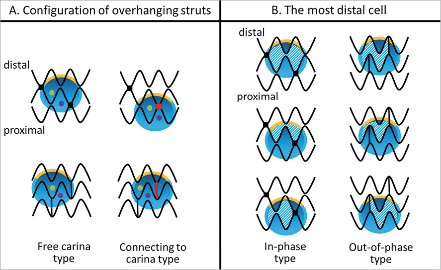
Figure 1. Classification of configuration of overhanging struts in front of the side branch ostium and definition of the most distal cell. Yellow line indicates the carina, red colour indicates the link between hoops connecting to the carina, green and purple dots indicate the distal and proximal recrossing position, and the shaded area indicates the most distal cell.
Statistical analysis
Discrete variables are presented as counts and percentages. Continuous variables are presented as means±SD, and ranges. Statistical analyses were performed with the use of SPSS 16.0 (SPSS Inc., Chicago, IL, USA). For comparisons of two continuous variables, a two-tailed unpaired Student’s t-test was used. A p-value less than 0.05 was considered statistically significant.
Results
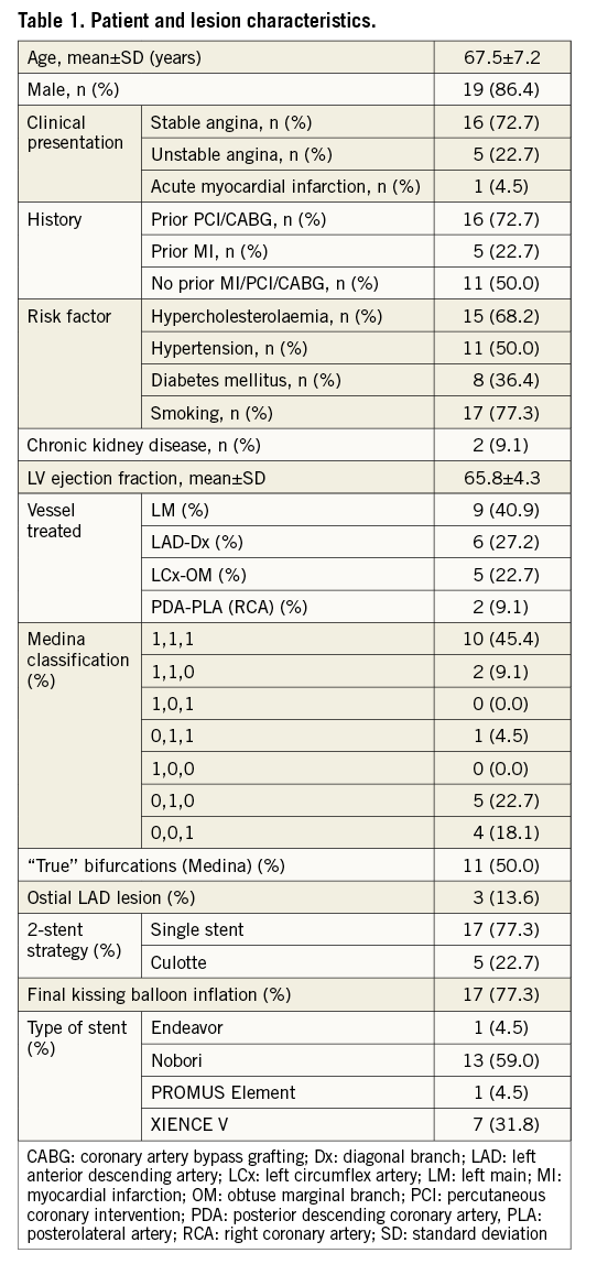
The total number of patients with bifurcation lesions during the study period was 61 (26% of total PCI in our institute). Of these, thirty-four patients underwent OCT examination. Twelve patients were excluded due to SB <2 mm (n=5), haemodynamic instability (n=2) and in-stent restenosis (n=5). Thus, 22 bifurcation lesions in 22 patients (16 stable angina and six acute coronary syndromes) were enrolled in this study. Patient and procedural characteristics are summarised in Table 1. Incidence of Medina true bifurcation23 (1,1,1; 1,0,1; 0,1,1) was 50%. Forty-one percent of target lesions involved distal left main bifurcation. Among those, three cases had an LAD ostial lesion.
A procedural flow chart is shown in Figure 2. After stent implantation in the main vessel across the side branch, 3D-OCT assessed the position of the second wire recrossing the deployed stent at the side branch ostium in 18/22 (81.8%) cases. In four cases, the recrossing position of the second wire could not be assessed due to main vessel guidewire shadow artefact, severe motion artefact or concealment by thrombus. The recrossing position was changed according to 3D-OCT findings in three cases. After deploying the second stent using the culotte technique (and before FKBD), the recrossing position was also confirmed in these four cases. Thus, in a total of 26 attempts to assess the recrossing position, 22 (84.6%) attempts were successful.
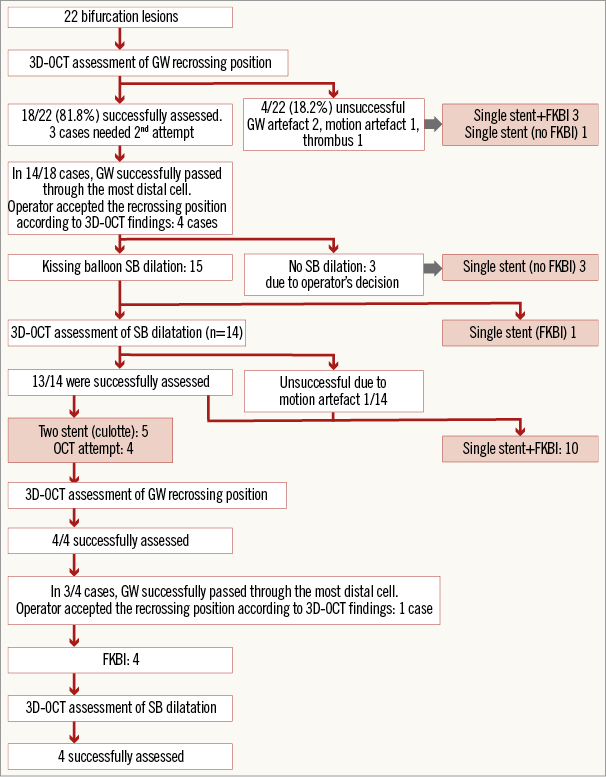
Figure 2. Procedural flow chart. 3D-OCT: three-dimensional optical coherence tomography; FKBI: final kissing balloon inflation; GW: guidewire
In 14/18 (77.8%) cases after the rewiring of the first stent deployment and in 3/4 (75.0%) cases after the rewiring of the second stent deployment, the guidewire successfully passed through the most distal cell. In the remaining five cases, the non-distal recrossing position was accepted by the operator according to the configuration of overhanging struts by 3D-OCT. The main reason affecting the operator’s decision was that the most distal cell appeared much smaller than the rewiring cell.
There were 13 cases where we assessed both the recrossing position and SB dilation after kissing balloon inflation by 3D-OCT. Of these 13 cases, six cases were connecting to carina type, while seven cases were free carina type. In 10 cases the recrossing guidewire passed through the most distal cell; however, in three cases the recrossing position was the proximal cell. All cases of free carina type complied with the most distal cell rewiring (n=7). After kissing balloon inflation, side branch ostia were evaluated with 3D-OCT. The percentage of ISA (%ISA) at the bifurcation segment in each category according to the recrossing position and the configuration of overhanging struts is summarised in Table 2. The %ISA of the free carina type was significantly smaller than that of the connecting to carina type (0.7±0.9% vs. 12.2±6.5%, p=0.0074). When %ISA at each bifurcation segment (four segments) was compared among the cases which complied with both the free carina type and the most distal cell rewiring (category A, n=7) and others (category B, n=6), the %ISA in category A tended to be smaller than that in category B in all segments. In particular, there were significant differences at all bifurcations and towards the SB (Figure 3). Unsurprisingly, angiographic findings had no correlation with ISA.
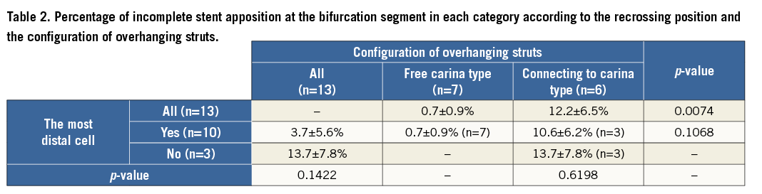
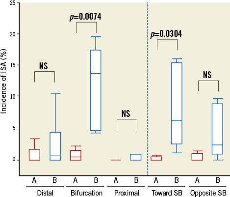
Figure 3. Incidence of incomplete stent apposition at each segment. A) The cases which comply with both the free carina type and the most distal cell rewiring. B) The cases which do not comply with either the free carina type or the most distal cell rewiring. ISA: incomplete stent apposition
3D-OCT can be helpful in practice in assessing and repositioning the guidewire, as illustrated in our representative cases (Figure 4-Figure 8). In case 1 (Figure 4), the recrossing position achieved angiographically was deemed suboptimal. Configuration of overhanging struts in front of the SB ostium was free carina type. As the first recrossing position was the proximal, the recrossing position was changed to the most distal cell. After FKBD, 3D-OCT demonstrated that the SB ostium opened well without any strut malapposition (%ISA at bifurcation, 0%). Conversely, the representative case 2 highlights a situation where the link connecting to the carina was in front of the SB ostium (Figure 5). Although the recrossing position was the most distal cell, the strut could not be stretched to the lateral vessel wall due to restricted mobility by the link connecting to the carina, resulting in ISA (%ISA at bifurcation, 16.3%). In the third example (Figure 6), the operator accepted the recrossing position which passed through the proximal cell with consideration for the link position. After FKBD, stent struts remained at the carina (%ISA at bifurcation, 19.5%). We have also shown serial 3D-OCT of two cases with culotte stenting (Figure 7, Figure 8). In case 4 (Figure 7), left main stenting was performed using the culotte technique. The wire passed through the most distal cell which had no links connecting to the carina after both the first and second stent deployment. After FKBD, there were no malapposed struts at the ostium of the LAD and the LCx. OCT and angiography at the follow-up demonstrated that the stent struts were well covered without restenosis (Figure 7). The final representative case (case 5, Figure 8) illustrates culotte stenting at the LAD diagonal bifurcation. The recrossing wire could not pass into the diagonal branch through the distal cell due to a small cell, and the link connecting to the carina was present. After deployment of the second stent using the culotte technique, the new metallic carina was created. The second rewiring could not select the distal cell, resulting in the presence of malapposed struts near the carina after FKBD. At follow-up, there was no angiographic stenosis at the bifurcation; however, thrombi attached to the metallic carina were seen on OCT (Figure 8).
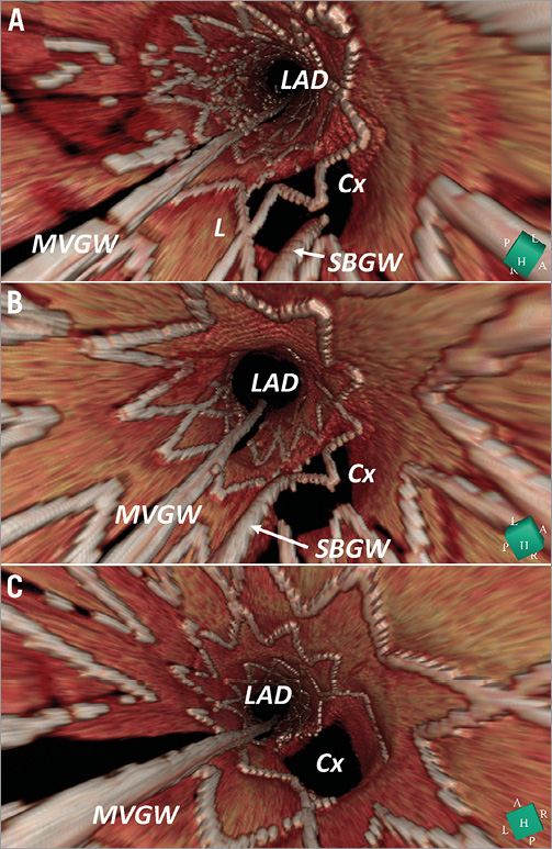
Figure 4. Representative case 1: the recrossing position was changed according to three-dimensional optical coherence tomography findings. A) First attempt at rewiring. B) Second attempt at rewiring. C) After final kissing balloon inflation. L: link; MVGW: main vessel guidewire; SBGW: side branch guidewire
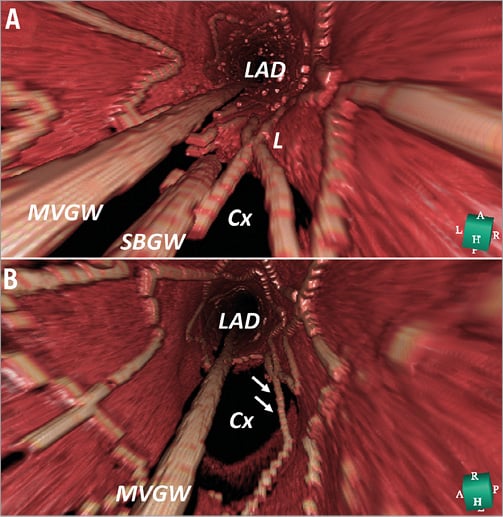
Figure 5.Representative case 2: connecting to the carina type configuration and the distal cell rewiring. A) After the rewiring, the side branch guidewire (SBGW) is located at the most distal cell. L indicates the link between hoops connecting to the carina. B) After final kissing balloon inflation, arrows indicate the malapposed strut. MVGW: main vessel guidewire
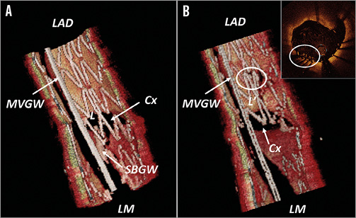
Figure 6. Representative case 3: connecting to the carina type configuration and the proximal cell rewiring. A) After the rewiring, the side branch guidewire (SBGW) is located at the proximal cell. L indicates the link between hoops connecting to the carina. B) After final kissing balloon inflation, L’ indicates the moving link distally. Circle indicates the overlapping struts. MVGW: main vessel guidewire
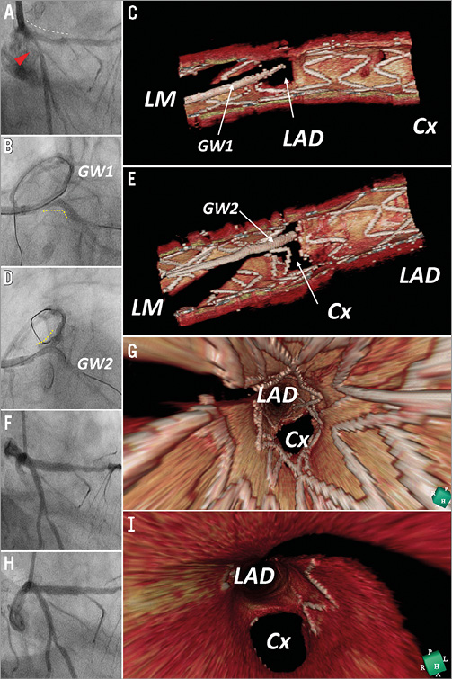
Figure 7. Representative case 4: serial 3D-OCT of culotte stenting for left main bifurcation. A) Pre-stenting, red triangle indicates the stenosis at the proximal circumflex coronary artery (Cx), white dotted line indicates diffuse plaque from the proximal left descending coronary artery (LAD) to left main (LM). B) After biolimus-eluting stent (BES) deployment from LCx to LM and rewiring to LAD (GW1), yellow dotted line indicates BES. C) Post kissing balloon inflation. D) Second stent (BES) was implanted from LAD to LM and rewired to Cx (GW2). E) GW2 locates the most distal cell and there are no links connecting to the carina. F) Final angiography after final kissing balloon inflation. G) Final 3D-OCT: there are no malapposed struts in the bifurcation segment. H) 3-month follow-up angiography. I) 3-month follow-up 3D-OCT.
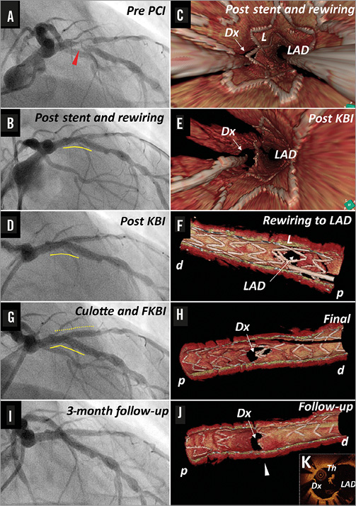
Figure 8. Representative case 5: serial 3D-OCT of culotte stenting for LAD/Dx bifurcation lesion. Red triangle indicates the target lesion of LAD, yellow line indicates the biolimus-eluting stent implanted in LAD, yellow dotted line indicates the second BES implanted in LAD/Dx. Th: thrombus, white arrow head indicates the corresponding site of cross-section (K); p: proximal; d: distal
Discussion
This study has shown, for the first time, the clinical application of high-quality off-line 3D-OCT to optimise side branch opening by identifying the configuration of overhanging struts in front of the side branch ostium according to the presence of the link between hoops at the carina (free carina type and connecting to carina type) and the appropriate distal cell for the recrossing position. We have shown that achievement of both distal rewiring and free carina type strut configuration can significantly reduce the incidence of ISA at the bifurcation.
So far, 3D-OCT has largely been confined to bench tests24-27, computer simulations5,28,29 and generation of pretty pictures for presentations. This is the first report demonstrating the utility of this technique in bifurcation stenting, especially for confirmation of the recrossing position13, which was successfully visualised in 85% of cases. The 15% failure was in the cases where the recrossing position was hidden by a thrombus (mainly STEMI patients) or by the MV guidewire shadow or misalignment of the stent due to motion artefacts. To visualise the implanted stents precisely, we used a slow pullback speed which increased the longitudinal resolution in ILUMIEN FD-OCT (100 frames/second). The cardiac motion artefacts can potentially increase on 3D-OCT imaging16,30. However, the commercially available newer-generation FD-OCT system (ILUMIEN OPTIS; St. Jude Medical) or optical frequency domain imaging (OFDI; Terumo) have a faster frame rate and may reduce the motion artefacts and obtain even better 3D-OCT images. Finally, it is also argued that 3D-OCT cannot be used in routine clinical practice as the off-line image reconstruction takes too long. The usual time taken for 3D reconstruction in this study was five to six minutes. This reconstruction time may be unacceptably long in acute haemodynamically unstable patients. The technology is rapidly evolving and in the near future we can expect systems generating on-line 3D reconstructions. With the advent of ILUMIEN OPTIS and the high resolution pullback mode, a second vendor now provides hardware compatible with the acquisition of high-quality 3D images.
Provisional stenting is the generally accepted technique for treatment of bifurcations31. A distal position of wire recrossing is important for better side branch dilatation after FKBD. Alegria-Barrero et al reported that the rate of ISA was significantly reduced when OCT (2D) was used to optimise the recrossing position compared with an angiography-guided group11. The incidence of ISA in their OCT-guided group was 7.5%. In our study, %ISA was 3.7% in all cases where the recrossing position was in the most distal cell, and it further decreased to 1.0% where the configuration of the overhanging strut was free carina type. The incidence of connecting to carina type was 7/13 (46.2%) in their study, which may explain the incidence of ISA11. We have shown that %ISA of all segments in the connecting to carina type tended to be greater than that in the free carina type, suggesting that stent distortion after FKBD was less affected when the stent was deployed in a favourable position against the SB ostium. It has also been shown that the position of the MV stent in relation to the SB ostium strongly correlates with the extent of strut deformation, with optimal SB access being obtained only if a cell was centrally placed with respect to the SB ostium28,29. Hence, the stent cell design can affect strut apposition after SB dilation, pointing towards mandatory KB when dilating an open-cell type stent28.
A second stent in the side branch is required in 5%-30% of true bifurcations because of dissection and/or slow flow in the side branch32. While stent malapposition in complex stenting (i.e., culotte) is considered to be greater than that in simple stenting25, Tyczynski et al have reported no difference in stent malapposition between single and complex stenting22. Possible reasons were: 1) the recrossing position was not confirmed by OCT, and it has been shown that in 1/3 of cases crossing was proximal in the first attempt; and 2) favourable stent positioning might be seen in only half of cases according to our study. Thus, the optimal condition (distal rewiring and favourable configuration) for kissing balloon inflation was achieved in only 1/3 of cases. In culotte stenting, since achievement of these conditions is required twice before kissing balloon inflation, the optimal condition after culotte stenting was achieved in only 1/9 of cases. In our representative case 4 (Figure 7), the distal recrossing position and favourable configuration after the first and second stent deployment resulted in 0% ISA after FKBD in culotte stenting. In case 5, we have shown that the wiring positing and configuration of overhanging struts can lead to ISA. Although we do not have the outcome data as yet, the appearance of thrombus at OCT follow-up of this case highlights the potential impact on clinical outcomes. To recross through the most distal cell would be possible in most cases under 3D-OCT guidance. This might reduce the incidence of ISA in complex stenting. If we could optimise stent deployment in a favourable position in relation to the side branch ostium, the clinical outcome of bifurcation stenting could potentially be improved.
Limitations
Though this is the largest series to date, this study has a modest number of patients. The cohort with full assessment of both the recrossing position and SB dilation after FKBD comprised 13 patients. This cohort was further subdivided into six cases with connecting carina type and seven with free carina type. These small subsets treated with heterogeneous strategies with or without FKBD might limit the interpretation of the study findings. Moreover, the impact of using 3D-OCT on long-term clinical outcomes is not assessed in the present study. Although the stent design might have influenced our findings, all stent types used in this study are in routine clinical practice. Since OCT imaging was acquired only from the main vessel, small incomplete stent apposition at the side branch side may not have been evaluated precisely. Finally, online 3D-OCT can never become online guidance. With OCT the operator may perform repeated pullbacks until he makes sure that the wire is in the best possible distal cell, but he cannot guide the recrossing itself.
Conclusions
In bifurcation stenting, confirmation of the recrossing position and assessment of the configuration of the overhanging strut in front of the SB ostium were feasible using 3D-OCT. The distal rewiring and favourable stent positioning were important to reduce the incidence of ISA.
Guest Editor
This paper was guest edited by Carlo Di Mario, MD, PhD, FRCP, FESC; NHLI Cardiovascular Biomedical Research Unit, Royal Brompton Hospital, London, United Kingdom.
| Impact on daily practice The rewiring position and the configuration of overhanging struts in front of the side branch (SB) ostium assessed by 3D-OCT may affect the strategy for bifurcational stenting. An operator can manipulate the second wire to pass through the proper cell with knowledge of the jailing configuration. When both the distal rewiring and favourable strut configuration are achieved, SB dilatation can reduce the floating struts from the SB ostium. This facilitates the second stent deployment, if necessary, and may improve the clinical outcome. |
Conflict of interest statement
T. Okamura received honoraria for technical consulting from Terumo. The other authors have no conflicts of interest to declare. The Guest Editor has no conflicts of interest to declare.