Abstract
With the advance of optical coherence tomography (OCT) technology, three-dimensional (3D) reconstruction based on the optical coherence tomography has become feasible. In bifurcation lesions, 3D OCT may guide positioning of the wire through the appropriate (distal) cells. The early studies suggested that such a guidance strategy could reduce the incidence of malapposition in bifurcation lesions. The pre-installed “real-time” 3D OCT on the console will promote the utilisation of 3D assessment in bifurcation treatment and possibly establish the clinical benefit of such guidance in the near future when investigated in a prospective study.
Introduction
THREE-DIMENSIONAL (3D) OPTICAL COHERENCE TOMOGRAPHY
Intravascular optical coherence tomography (OCT) is a light-based imaging modality which provides high-resolution images of the coronary arteries1-3. With its unrivalled high resolution (10-15 microns) compared with other coronary imaging modalities (IVUS: 100-150 microns, angiography: 100-200 microns), OCT is increasingly used to investigate the pathological mechanisms of coronary artery disease and/or to evaluate the interaction between the coronary artery and the implanted stent.
The recently developed optical frequency domain imaging (OFDI) technique (or Fourier-domain OCT [C7/C8; St. Jude Medical, St. Paul, MN, USA, and OFDI; Terumo Corp., Tokyo, Japan]) provides higher image acquisition speeds, greater penetration depth, and a higher-quality image resolution as compared to conventional time-domain OCT4-7. Furthermore, its higher frame rate and higher pullback speed reduce the impact of possible motion artefacts and improve longitudinal resolution, facilitating a more detailed depiction and more accurate quantitative analysis of coronary arteries as compared to time-domain OCT8,9. These new imaging systems have enabled 3D reconstruction to enhance the understanding of complex coronary lesions and the complex interaction between the coronary devices and the vessels by assembling/compiling the two-dimensional (2D) cross-sections (Online Figure 1).
In general, the potential clinical applications of 3D technology include the global assessment of areas of possible stent malapposition, the identification and localisation of the extent of thrombus1, the assessment of complex lesions and the potential guidance of PCI. For example, if clustering of malapposition is obvious on the 3D reconstruction, the operator could consider performing further post-dilatation. Similarly, detection and localisation of thrombus could trigger subsequent additional thrombectomy and/or administration of IIb/IIIa inhibitors2,3.
CLINICAL APPLICATION OF 3D OCT RECONSTRUCTION IN BIFURCATION
In bifurcation, it is difficult and not always feasible to visualise with 2D imaging the complex anatomy of the bifurcation and the effects of intervention1. With 3D OFDI it is easier to recognise the anatomical changes after intervention than with 2D OCT. For example, in the endoscopic 3D view of the coronary artery from the proximal LAD to the distal LAD (Online Figure 2), it is clearly demonstrated that, after stenting in the main vessel (LAD), the bifurcation carina of the LAD-diagonal was shifted towards the side branch, creating a stenosis at the ostium.
After stenting in a main branch, the pullback from the side branch is not always feasible and implies additional contrast medium administration. Quantitative measurements of the side branch ostial area based on 3D reconstructed OCT pullback from the main branch may therefore have clinical application, facilitating the assessment as to whether the side branch is haemodynamically obstructed. Recently, dedicated software has been developed to enable ostial area assessment in a reconstructed cross-section (cut plane) that is perpendicular to the side branch centreline4. It has been demonstrated that the cut-plane analysis of an OCT pullback of the main branch has a high correlation with reference measurements performed in a side branch OCT pullback and also lower number of errors compared with conventional analysis4.
Another indication is the serial assessment of the overhanging bioresorbable scaffold struts in front of the small side branch ostium5,6. The 3D image could be used to classify the jailed side branch according to the number of compartments created by the criss-cross of the struts as well as the configuration of the jailing struts (Figure 1). At follow-up, the 3D image demonstrates the alteration of the carina due to the bioresorption process. Three-dimensional OCT can also be applied to judge the presence or absence of damaged scaffold struts after complex bifurcation scaffolding (such as T-scaffolding with a combination of a metallic stent) (Figure 2).
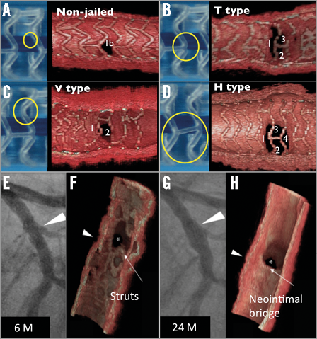
Figure 1. Side branch jailing with a bioresorbable scaffold. A-D illustrate a proposed classification of jailed side branch by bioresorbable scaffold at baseline according to the number of compartments divided by the jailing struts (A: strut free, B: 3 compartments, C: 2 compartments, D: 4 compartments) as well as the configuration of jailing struts (B: T-shape, C: V-shape and D: H-shape). The 3D OCT is applied to a serial assessment of jailed side branch ostia. Six months after implantation the ostium of the diagonal branch was still jailed with a hoop of bioresorbable scaffold (E & F), which completely disappeared at two-year follow-up (G & H). The jailing hoop now creates a new bifurcation carina with a neointimal bridge. (Figures adapted with permission from Okamura et al6)
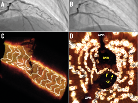
Figure 2. After treatment of a bifurcation lesion with a bioresorbable scaffold in the main branch and a metallic stent in the side branch. A LAD/diagonal bifurcation lesion (A) was treated with an Absorb bioresorbable scaffold (main branch) and a metallic stent (side branch). A final kissing balloon inflation (FKB) was then performed at 4 atm. OCT 3D reconstruction (C & D) was performed to ensure the preserved integrity of the bioresorbable vascular scaffold rings and complete opening of the side branch ostium. (Figures courtesy of V. Dzavik)
GUIDANCE IN THE REWIRING OF A DISTAL CELL OF THE STENT OVERHANGING A SIDE BRANCH OSTIUM
The important potential practical application of 3D FD-OCT is to guide the rewiring of the distal cell of the jailed side branch ostium to minimise the risk of struts pushed inside the main vessel creating a so-called de novo “metal carina” (Figure 3)7.
The protrusion of the metal carina into the main branch is determined mainly by the re-crossing point. In general, distal re-crossing promotes a better ostial side branch stent coverage and apposition, while proximal re-crossing results in a lower strut coverage of the side branch ostium and more overhanging metal into the main branch. In a phantom model, after proximal re-crossing and kissing balloon, the metal still remains in front of the side branch, protruding into the lumen in the main branch, while after distal re-crossing and balloon inflation the rings of the main branch struts are expanded to appose themselves to the vessel wall rim of the side branch ostium, resulting in a jailed side branch without overhanging struts (Figure 3, Moving image 1). The computational flow simulation of the shear rate showed that after proximal re-crossing the remaining unapposed metal carina (strut jailing the side branch) could cause an abnormal high shear rate level above 2,000 s–1, whereas after distal crossing and kissing balloon less disturbance of shear rate exists8.
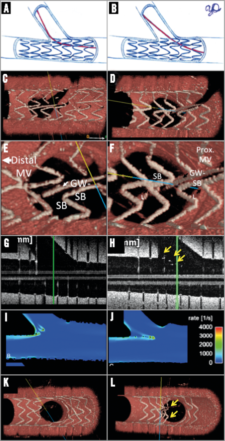
Figure 3. Stent configuration before and after kissing balloon in different rewiring positions. After stenting in the main branch, rewiring the side branch through the strut of a stent is usually possible through two or three different cells. The choice of re-crossing cell influences the acute results as assessed by OCT. In a phantom model, the distal re-crossing (A) is confirmed by 3D OCT (C & E). After kissing ballooning, the bifurcation carina is free of struts (G & K) and there is a minimum influence on the shear stress simulation (I)8. On 3D OCT, the side branch ostium is widely open. On the contrary, when the proximal cell is rewired (B, D & F), the metallic struts still remained unapposed in the lumen even after kissing balloon (arrows in H), creating a new metallic carina, which disturbs the shear stress (J). 3D OCT confirms the presence of metallic carina. (Panels I and J were adapted from Foin et al with permission8.)
The feasibility of OCT guidance in bifurcation lesions (either with 2D or 3D images) and its potential benefit were assessed in only a few studies. Alegria-Barrero et al reported9 that, in 52 patients undergoing elective treatment of bifurcation lesions using provisional stenting as the default strategy, patients who were treated using OCT-guided re-crossing (n=12) had a significantly lower number of malapposed stent struts, especially in the quadrants towards the SB ostium (9.5% [7.5-17.4%] in the OCT-guided group vs. 42.3% [31.2-54.7%] in the angiography-guided group, p<0.0001). In 33% of the OCT-guided group after the first attempt to re-cross the stent towards the side branch, the wire was found to have crossed in a proximal cell, requiring a second positioning of the wire and in one case even a third attempt to cross through a distal cell successfully. In this study, OCT guidance was mainly based on 2D cross-sections.
More recently, Okamura et al demonstrated10,11 in a series of 22 patients that off-line 3D OCT reconstruction during a PCI procedure was feasible. Once OCT images had been acquired, raw data were transferred to the off-line workstation, where automatic stent strut detection and enhancement were undertaken. A 3D OCT reconstruction was completed in five to six minutes and 3D images were used to confirm the re-crossing position of the wire after stent implantation in a bifurcation lesion (Figure 4). The assessment of the side branch ostium by off-line 3D OCT was feasible in all cases with the exception of four cases in which guidewire shadow artefacts, severe motion artefacts or presence of intraluminal mass hindered the evaluation. According to the 3D assessment, malapposition in bifurcation lesions was influenced not only by the re-crossing position but by the configuration of jailing struts. More specifically, the presence of a longitudinal link between the rings in front of the ostium was associated with more frequent malapposition compared to the cases without a longitudinal link.
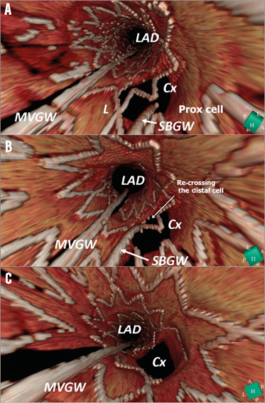
Figure 4. 3D OCT images during left main intervention. During percutaneous coronary intervention to a left main lesion, the re-crossing position of the guidewire towards a side branch was assessed by 3D OCT. After the main branch stenting, 3D OCT demonstrated that the rewiring was through the proximal cell (A). The re-crossing point was changed through the distal cell (B) and a kissing balloon was performed, resulting in a wide opening of the side branch ostium free from metallic structure in front of the side branch (C). Cx: circumflex; LAD: left anterior descending artery; L: link; MVGW: main vessel guidewire; SBGW: side branch guidewire. (Reprinted from Okamura et al11, with permission)
The study demonstrated the feasibility of 3D OCT imaging guidance during the procedures, but it is noted that the 3D reconstruction was still conducted off-line.
CURRENT LIMITATIONS AND THE FUTURE
In the initial experiences in 2011, 3D reconstruction was a time-consuming process: first, all 2D images were outputted with bitmap sequences. Subsequently, in bitmap images, the struts were manually identified off-line and segmented so that the 3D software could differentiate the strut from the vessel wall. This process was very time-consuming: for example, a pullback of an 18 mm stent generated approximately 150 cross-sectional images, each of which was post-processed manually. The post-processed 2D image sequence was then imported into dedicated 3D software such as OsiriX (Pixmeo SARL, Bernex, Switzerland) or INTAGE Realia. In the initial experience, it took at least two hours to obtain a 3D image for a short stent. With the advent of software, the strut detection became automatic12. Such software significantly reduced the reconstruction time to a mere five to ten minutes, which enables off-line 3D reconstruction during the procedure. However, data needs to be transferred to an off-line computer and at least two software packages are needed to obtain the final 3D images.
More recently, 3D reconstruction with strut segmentation has become feasible on-line. For example, the Terumo OFDI console has on-line software of 3D imaging with a possibility of stent enhancement, which enables on-line reconstruction within one minute (Moving image 2). To investigate the potential clinical benefit of 3D OFDI guidance, it would be important to collect the clinical data prospectively under “guidance” criteria. The Medis company (Leiden, The Netherlands) has also developed on-line OCT software where the 3D angiography and OCT are co-registered with a possibility of 3D reconstruction.
Conclusion
With the advance of OFDI technology, 3D reconstruction based on OCT has become feasible. In the period 2011-2014, the potential of the technology was demonstrated in off-line 3D OCT with manual strut identification. In bifurcation lesions, 3D OCT may guide positioning of the wire through the appropriate (distal) cells. The early studies suggested that such a guidance strategy could reduce the incidence of malapposition in bifurcation lesions. Currently, a few software facilitate the 3D OFDI with strut detection on-line. The equipped “real-time” 3D OFDI will promote the utilisation of 3D assessment in bifurcation treatment and possibly establish the clinical benefit of such guidance in the near future when investigated in a prospective study.
Conflict of interest statement
The authors have no conflicts of interest to declare.
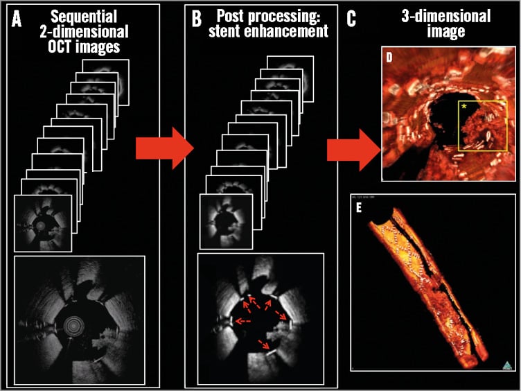
Online Figure 1. General workflow for the 3D reconstruction process following stent enhancement. After acquisition of sequential 2D OCT/OFDI images (A), the 2D images are further processed. Each stent strut in all cross-sections is highlighted with white (B: red dotted arrows). After the stent enhancement, the 3D images are reconstructed using dedicated software (OsiriX) (C). Due to the stent enhancement, the stent structure (white in panels D & E) is clearly distinguished on 3D images from the vessel structure and the intraluminal mass (red in D & E) that creates a thrombotic arch. 3D images are presented typically as a fly-through (or endoscopic) view (D) or a half-cut view (E).
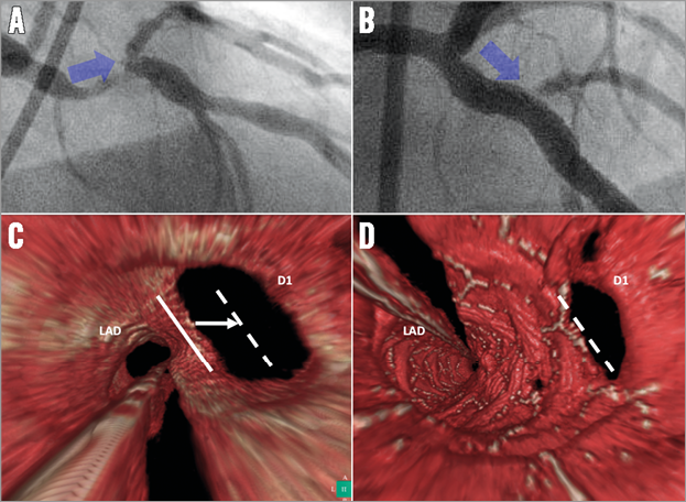
Online Figure 2. A stent was implanted to treat a bifurcation lesion of the LAD and the diagonal branch. On angiography, the ostium of the diagonal branch became stenotic after stenting (blue arrow in A [pre-procedure] and B [post procedure]). Fly-through 3D OCT images before and after stenting (C & D, respectively) reconstructed to demonstrate the anatomical changes in the bifurcation lesion with an endoscopic-like view which looks at the bifurcated lesion from the proximal LAD into the two daughter branches. After the procedure, the position of the carina (white line in C) was shifted towards the side branch (dotted white line in C & D), which is considered to be the cause of the post-procedural stenosis at the side branch ostium.
Online data supplement
Moving image 1. OFDI pullback after kissing balloon in different configurations.
Moving image 2. On-line 3D reconstruction on console.