Abstract
Aims: The aim of this study was to characterise the coronary stent longitudinal resistance of new coronary stents under worst case clinical crossing simulated configurations.
Methods and results: Six coronary balloon-expandable stents were evaluated using two different tests. The first was a direct parallel plates longitudinal crush resistance test: it was conducted on stents deployed to 3 mm diameter, and three samples of each model were used. The second was performed by tracking over the wire and deploying the stents in two types of coronary model: good and malapposition models. Two samples of each model were used for this test. After deployment, a PTCA balloon was advanced over the wire. For each stent, the force required for balloon tracking and the stent shortening were recorded. In the first crush test, three out of six stent models demonstrated higher longitudinal crush rates compared to the Resolute Integrity (Medtronic, Minneapolis, MN, USA): PROMUS Element™ (Boston Scientific, Natick, MA, USA) p<0.0001, Coroflex® Blue (B. Braun, Melsungen, Germany) p<0.0001, and Orsiro (Biotronik, Berlin, Germany) p=0.038. In the simulation test, there were no statistical differences when comparing all good and malapposition groups.
Conclusions: Lower resistance to mechanical longitudinal compression of some stents did not correlate to significantly higher crush rates in simulated clinical conditions. Nevertheless, it would be useful for cardiologists to be aware of the actual mechanical characteristics of new stents to take them into account and thus minimise longitudinal compression during difficult stent implantations.
Introduction
A new generation of drug-eluting stents (DES) has been designed with thinner struts and with a reduced number of connectors between the hoops in comparison to the first CYPHER® stent (Cordis, Johnson & Johnson, Warren, NJ, USA). This is in part due to the use of alloys such as cobalt-chromium or platinum-chromium, which allows for the design of stents with thinner struts, while maintaining radial resistance and radiopacity. These recent devices generally have a series of hoops to provide radial resistance to crushing when scaffolding the vessel wall, and connectors between the hoops to hold the stent together. Stents with thin struts have added benefits such as increased deliverability and conformability. Moreover, the number, the orientation, the shape, the thickness and the material of the connectors are major contributors to stent longitudinal flexibility and deliverability before deployment, and contribute to vessel conformability, longitudinal strength and stability after deployment1.
As a trade-off, these innovations may adversely affect stent longitudinal resistance and, consequently, stent designs are more sensitive to shortening or elongation when struts are being pushed or pulled apart. Clinical observations of significant longitudinal compression in certain new coronary stents have been reported2-5, when re-crossed with other devices such as post-dilatation balloons or IVUS catheters. These longitudinal compressions have been observed with various stent platforms, particularly with the PROMUS Element platform and to a lower extent with the Driver stent platforms.
The aim of this bench-top study was to evaluate the effect of stent design on longitudinal compression behaviour, when subjected to forces similar to those seen in clinical practice.
Bench testing1 was initially performed in a rather crude way and we performed additional bench-top testing to simulate clinical stent usage in order to reassess the value of the initial testing with direct application of forces. Our objective was to provide indications on whether there were quantifiable differences in longitudinal compression resistance among various stent designs.
Methods
The longitudinal strength of six new stent designs was experimentally evaluated under clinically relevant compression forces, using a bench-test method and standardised test protocols specifically developed for this purpose.
The bench-top comparative test included two crush tests. First, a direct parallel plates longitudinal crush resistance test was conducted after deploying the three stents to 3 mm diameter. Three samples of each model were used. The second test simulated two clinically relevant situations in coronary vessel models (good and malapposition cases) where stents were tracked over a 0.014’’ interventional wire, positioned and deployed in either good apposition or malapposition coronary vessel models, six samples each, respectively. After deployment and withdrawal of the balloon, a new balloon was advanced over the 0.014’’ wire automatically. For each sample, the force required for tracking the balloon through the stent was recorded and the change of stent length after balloon crossing was calculated.
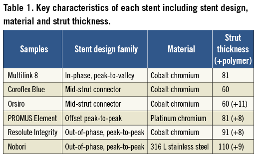
The six platforms were two BMS, Multilink 8, 3.0×18 mm (Abbott Vascular, Santa Clara, CA, USA) and Coroflex® Blue 3.0×19 mm (B. Braun, Melsungen, Germany) and four DES: Orsiro 3.0×18 mm (Biotronik, Berlin, Germany), PROMUS Element™ 3.0×20 mm (Boston Scientific, Natick, MA, USA), Resolute Integrity 3.0×18 mm (Medtronic, Minneapolis, MN, USA) and Nobori 3.0×18 mm (Terumo, Tokyo, Japan). The Multilink 8 is the BMS platform of the XIENCE PRIME™ DES (Abbott Vascular, Santa Clara, CA, USA). Furthermore, the Nobori DES has abluminal coating only while all other DES have coating around the entire strut. Table 1 summarises the key characteristics of each design.
Direct longitudinal crush resistance test
The nominal expansion diameter of stents used in this study was 3.0 mm with stent lengths ranging from 18-20 mm. First, stent samples were deployed at ambient temperature, without external stress, to an internal diameter of 3.0 mm according to the compliance table (i.e., external balloon diameter). Initial length and diameter of stent samples were measured using a SmartScope optical gauging machine, accuracy 5 micrometres (OGP, Inc., Singapore) and recorded (Table 2). Three samples from each design were tested. Samples were positioned on a specific vertical stent fixture (Figure 1). The sample stood vertically with its inferior extremity guided by a specific stent fixture. A piston, controlled by a stepper motor, was used to compress the stent upper extremity at a fixed rate while measuring the compression force using a force gauge (MARK-10 BG2; Mark-10 Corporation, Copiague, NY, USA). Piston displacement and force were recorded. The test was stopped either when the force reached 1 newton (N) or when the stent length reduction reached 50%. A video camera was used to record the stent behaviour during compression. Stent samples were removed from the fixture. Final length and diameter were measured (using the SmartScope) and recorded. Stent length reduction was calculated and expressed in %:
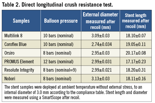
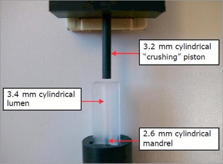
Figure 1. Stent specific vertical fixture for longitudinal compression. The expanded stent is placed in the cylindrical lumen and the crushing piston can compress it.
Length reduction (%)=([initial length – final length] / initial length)×100
Simulation longitudinal length stability test
The objective was to characterise stent longitudinal resistance under simulated clinical worst case crossing configurations in good and malapposition bench-top models. The simulation longitudinal length stability tests were performed using the IDTE 2000 (Interventional Device Testing Equipment; Machine Solutions, Inc., Flagstaff, AZ, USA) using water at a constant flow of 0.02 L/min and a temperature of 37°C±2°C.
The same accessories were used for all tests: introducer sheath (Radiofocus® Introducer II, 6 Fr; Terumo), wire (HI-TORQUE BALANCE MIDDLEWEIGHT UNIVERSAL II, 0.014”, L=190 cm; Abbott Vascular), guiding catheter (Z2™, 6 Fr, AL1.0, ID=0.070”, OD=0.081”, L=100 cm; Medtronic), dilatation catheter (NC Quantum Apex™ monorail PTCA Dilatation Catheter, 3.0×18 mm; Boston Scientific). After stent deployment (good or malapposition case), a non-compliant Quantum Apex monorail balloon (pushing balloon) was pushed automatically to cross the stent.
A predefined and specific tortuous path for trackability was developed to deploy the stent in a coronary vessel model (3.1 mm internal diameter silicone tube) to simulate good and malapposition cases (Figure 2). The path was 75 cm long and had five curves: an aortic arch model (curves 1 and 2: 9 and 4 cm radius of curvature), entrance into left coronary artery (curve 3: 2 cm radius of curvature), and two curves in the coronary artery of 5 cm and 2 cm, respectively. At the end of the path, a specific module was used for the deployment of each stent (Figure 3). To simulate a good apposition case, a 3.1×0.5 mm transparent silicone tube (length=120 mm) was used as an artery model. The malapposition model used a 3.1×0.5 mm transparent silicone tube (length=60 mm) with a 5×2 mm cut at its proximal end, which was inserted in a 4×0.5 mm transparent silicone tube (length=110 mm). The stent proximal end fitted into the 3.1 mm internal diameter (ID) tube proximal end. The combined effect of the cut in the 3.1 mm ID tube and the insertion within the 4.0 mm ID tube forced the stent in this area not to be apposed to the silicone wall (Figure 4).
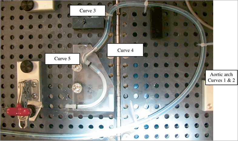
Figure 2. Trackability through a tortuous path model. The specific path is 75 cm long, with five curves. Curves 1 and 2 represent the aortic arch (9cm and 4 cm radius of curvature), curve 3 represents the entrance into the left coronary artery (2 cm radius of curvature), and the two curves 4 and 5 (5 cm and 2 cm radius of curvature, respectively) represent the coronary artery. A specific module is used for each stent at the end of the path.
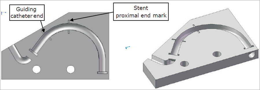
Figure 3. The specific module where the stent is deployed. Each stent has its specific module.
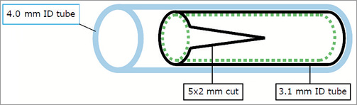
Figure 4. Model of artery used in the malapposition case. Transparent, 0.5 mm thick silicone tubes with different internal diameters (ID) were used in the models. For the good apposition case, a tube with a 3.1 mm ID (length=120 mm) was used. To simulate malapposition, a 3.1 mm ID tube (length=60 mm) with a 5 mm×2 mm cut at its proximal end, was inserted into a 4 mm ID tube (length=110 mm). The stent was deployed inside the 3.1 mm ID tube so that the proximal end of the stent fitted inside the proximal end of the tube. The combined effect of the cut in the 3.1 mm ID tube and its insertion inside the 4 mm ID tube caused the stent to be malapposed in the area of the cut (there is a free space between the stent and the 4 mm ID tube).
A video camera was used to record stent behaviour. The second pushing balloon was manually advanced so that its distal tip reached the distal end of the guiding catheter. Then, the balloon catheter was automatically tracked through the stent. The balloon catheter tracking force was measured on the IDTE 2000 proximal load cell. Balloon tracking was stopped if 2 N force was reached; this level of force is the maximum seen advancing in the typical coronary system. The crush test sequence was repeated a maximum of five times in order to try to catch the stent. If the 2 N force occurred before the last attempt, the test was stopped. Finally, the balloon was withdrawn manually. The following data were recorded: maximal force (N), stent length difference on the external wall (outside of the curve) (%), stent length difference on the internal wall (inside of the curve) (%), and migration (%). Maximum, minimum, mean and standard deviations of percent stent length reduction were assessed.
Pictures of the initial and final positions of the sample were extracted from the film and recorded. Initial and final sample positions were measured on the external and internal walls, on the proximal and distal ends. Stent length differences at external and internal walls were calculated, expressed in % and recorded:
Stent length difference (%)=([initial length – final length] / initial length)×100
Statistical analysis
For the direct longitudinal crush resistance test, we used an ANOVA analysis to assess statistical differences between values of each group (three samples per group, six groups). Each measurement of longitudinal crush (%) and of force (N) was used as the primary output. In both good and malapposition cases, we used an ANOVA analysis to assess statistical differences between values of each group (six samples per group, six groups), and to assess statistical differences between good and malapposition cases for each sample model. Each measurement of crush (external and internal) (%), maximum force (N) and migration (%) was used as the primary output. If the ANOVA analysis showed significant differences (p-value <0.05), we then computed 95% confidence intervals and p-values on the differences between the values of groups using the Tukey’s Honest Significant Difference method. The function is corrected for the unbalanced design and allows the taking into account of the entire data set as opposed to multiple comparison t-tests. The results of the Tukey’s Honest Significant Difference method are interpreted as significant if the p-value is <0.05.
Results
DIRECT LONGITUDINAL CRUSH RESISTANCE TEST
All the stents of the first bench test shortened when a compressive force was applied to them. Figure 5 shows the curve effort versus longitudinal strain for each group of three samples, and the crush due to a 1 N compressive force. Figure 6 summarises the behaviour of each group of stents (mean shortening for the three stents) considering a longitudinal crush under a force from 0 to 1 N. Figure 7 shows the photographs of the different stents after the crush due to a 1 N compressive force.
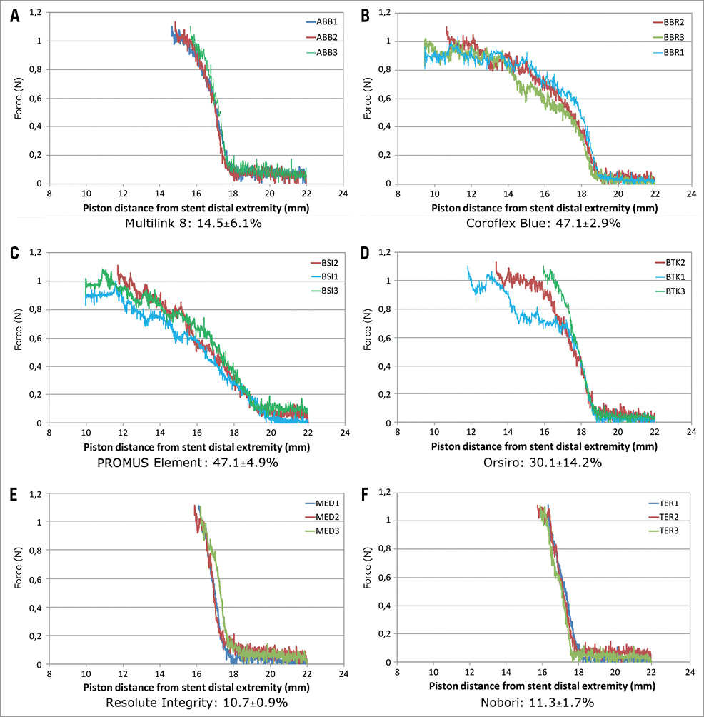
Figure 5. Direct longitudinal crush resistance: crush (%) under a 1 N compressive force. Three samples (numbered 1, 2 and 3) of each stent model were used. This figure shows the curve effort (force) versus longitudinal strain for each group of 3 samples, and the crush (%) resulting under a 1 N compressive force. All the stents of this first bench test shortened when a compressive force was applied to them.
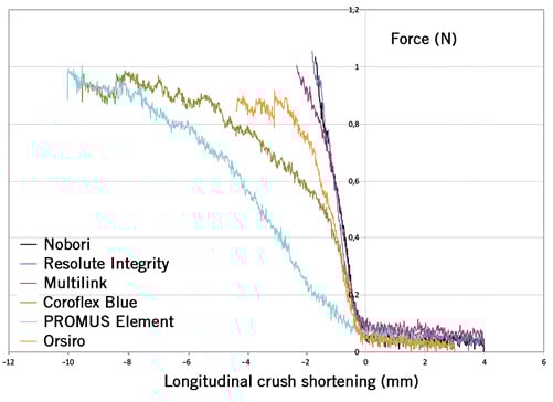
Figure 6. Direct longitudinal crush resistance: shortening under a force from 0 to 1 N. This is a comparison of the behaviour of each group of stents (mean shortening for the 3 stents) considering the longitudinal crush under a force from 0 to 1 N. Three of the six stent models demonstrated significantly higher longitudinal crush rates in comparison with the Resolute Integrity: the PROMUS Element (p<0.0001), the Coroflex Blue (p<0.0001) and the Orsiro (p=0.038). The Nobori had a statistically significant lower crush strain than the Orsiro (p=0.045), the PROMUS Element (p<0.0001) and the Coroflex Blue(p<0.0001). The Multilink 8 also had a statistically highly significant lower crush strain than the PROMUS Element (p<0.001) and the Coroflex Blue (p<0.001).
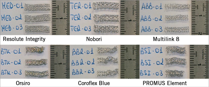
Figure 7. Longitudinal distorsion of deployed stents. This figure shows the photographs of the six different stents after crushing under a 1 N compressive force.
The first mechanical conclusion resulting from these trials is that the Resolute Integrity, the Nobori and the Multilink 8 had significantly higher pure mechanical resistance to pure mechanical longitudinal crush than the Orsiro, the Coroflex Blue and the PROMUS Element (under a 1 N compressive force, without any radial stress).
SIMULATION LONGITUDINAL LENGTH STABILITY TRIALS
Graphs of the proximal strength versus “pushing” balloon position, pictures of the initial and final states of the sample, and pictures of the final state under radiography were obtained. Among the recorded data for each sample, maximal force (N), stent length difference on the external wall (%), stent length difference on the internal wall (%), stent length differences at external and internal walls and the rate of migration (%) were calculated and expressed in %. The results were grouped by stent model and by good or malapposition cases.
Figure 8 summarises the data in a good apposition case and Figure 9 summarises the data in a malapposition case. It was observed that stent migration occurred for only one group of stents (Coroflex Blue). The cause of this Coroflex Blue stent migration could have been due to a problem of high recoil rate.
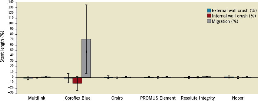
Figure 8 .Good apposition cases. Positive stent length difference represents a decrease in stent length. Negative stent length difference represents an increase in stent length (the stent can become elongated when the distal tip of the balloon catches the distal edge of the stent when crossing). There was no statistically significant difference in internal wall crush between the stents (p=0.899) and, after exclusion of the Coroflex Blue stent, there was no significant difference for external wall crush (p=0.395). The Coroflex Blue stent has a statistically highly significant higher migration rate than the other stents (p=0.0002). This result is probably related to the Coroflex Blue stent external diameter value (inferior to the silicone tube internal diameter).
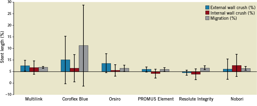
Figure 9. Malapposition cases. For the external wall crush, there was no statistical difference when comparing the remaining five malapposed stents (p=0.19). Concerning the internal wall crush, there was also no statistical difference between any of the malapposed stents (p=0.185). Concerning migration rate, there were no statistical differences between stents (p=0.1284)
In the external wall crush Anova analysis of the five remaining groups of stents, there were no statistical differences when comparing all good apposition groups (p=0.836) and all malapposition groups (p=0.447). For each group of stents, there were no statistical differences when comparing good versus malapposition for the PROMUS Element samples (p=0.696), the Orsiro samples (p=0.179), the Resolute Integrity samples (p=0.554), Coroflex Blue samples (p=0.298) and the Nobori samples (p=0.907).
In Multilink 8 samples, the malapposition group had statistically significant different external wall crush results compared to good apposition (p=0.0271).
In the internal wall crush comparison of the six groups of stents, there was a significant statistical difference among all good apposition groups (p=0.011). Coroflex Blue had significantly higher internal wall crush than the other groups (p range from 0.015 to 0.038), but there were no statistically significant differences among all malapposition groups (p=0.447). For each group of stents, there were no statistically significant differences when comparing good apposition versus malapposition for the Multilink 8 samples (p=0.141), the Coroflex Blue (p=0.065), the PROMUS Element samples (p=0.708), the Orsiro samples (p=0.612), the Resolute Integrity samples (p=0.219) and the Nobori samples (p=0.268).
Concerning the maximal force required for tracking the balloon, there were no statistically significant differences among all good apposition groups (p=0.752), but there was a statistically significant difference among all malapposition groups (p=0.043). The Multilink 8 stent had significantly higher maximum force results than the forces measured for the PROMUS Element stent tracking. For each group of stents, there were no statistical differences when comparing good versus malapposition for the Multilink 8 (p=0.236), the Coroflex Blue (p=0.814), the PROMUS Element (p=0.069), the Orsiro (p=0.798), the Resolute Integrity (p=0.926) and the Nobori (p=0.646).
Discussion
The bench-test results of the present study allow for two mechanical conclusions. According to our first longitudinal crush test the Resolute Integrity, Nobori and Multilink 8 stents have a significantly higher pure mechanical resistance. Nevertheless, in “clinically relevant” situation testing, we found no statistically significant differences in the longitudinal crush for both good apposition and malapposition cases, except for the Coroflex Blue.
DIRECT LONGITUDINAL CRUSH RESISTANCE TEST
The results of our first longitudinal crush test confirm some previous works reported in the literature. Prabhu et al6 have also shown that the Element family (including the Omega and Ion) may shorten up to 47% under a 0.49 N force, as have the data already described by Ormiston et al7. According to these authors, the PROMUS Element and the Driver with only two connectors between hoops were more likely to distort under longitudinal loads than those with three or more connectors. For example, the stainless steel CYPHER SELECT (Cordis) with a 6-connector platform had the greatest resistance to longitudinal compression. However, this first DES is no longer widely used because of its bad flexibility, deliverability and crossing profile; the side branch access is also limited. Furthermore, the side branch access of the first-generation DES is also limited. Basalus et al8 showed that that the closed cell stent platform CYPHER DES had particularly small cells even after aggressive post-dilatation. Nevertheless, this strong stent was not free from fatigue stent fractures9, inducing long-term in-stent restenosis. Interestingly, platinum and cobalt chromium, the alloys used in later-generation DES, are less susceptible to corrosion than 316 L stainless steel10. The number of connectors does not seem to be the only component of longitudinal deformation. In our first “piston” test, despite its two connectors, the Resolute Integrity had the greatest longitudinal resistance to compression, probably explained by its helical single wire winding.
Concerning the stent thickness, we note that the thinner stent Coroflex Blue evaluated on our first bench test (despite its three connectors) had a significantly higher direct longitudinal deformation compared to the Resolute Integrity (p<0.0001).
The reduction of stent thickness has successfully improved stent flexibility and deliverability. Furthermore, Kastrati et al11 have demonstrated that the use of a device with a thinner stent was associated with a significant reduction in angiographic and clinical restenosis after coronary artery stenting in vessels >2.8 mm in reference diameter. In the second generation of DES, thinner stent struts were associated with improved clinical outcomes due to a better and faster re-endothelialisation12. In conclusion, a compromise between a decrease in stent thickness and a good longitudinal resistance has to be found and the stent thickness should not be less than 60 µm.
SIMULATION LONGITUDINAL LENGTH STABILITY TRIALS
Our first bench test concerned longitudinal resistance of stents deployed in “free air” without any external radial force applied around the stent as it would be in clinical conditions. Our second bench test simulated a crush test of a stent implanted in two different types of curvature, one simulating a good apposition and the second a malapposition case. We found no statistically significant differences in longitudinal crush among all stent models, except for the Coroflex Blue, for both good apposition and malapposition cases. The Coroflex Blue showed significantly higher longitudinal crush in the malapposition model compared to the good apposition model. A high recoil value may be the explanation for the unfavourable behaviour of the Coroflex Blue.
These results, coming from simulating clinical situations, may explain the clinical observations published on a few stents among several thousand new stent implantations. On the other hand, longitudinal compression has not been reported in large multicentre trials and international registries. Finet et al13 suggested that not all stent platforms have equal radiopacity, and that the PROMUS Element being much more “visible” can lead interventional cardiologists to a much easier detection, hence the larger number of PROMUS Elements reported.
CLINICAL IMPLICATION
There have been great clinical advances in coronary bare metal stent platforms over the last three decades. Thinner struts, lower metal/artery ratio and lower fixed connectors between cells have contributed to providing us with stent platforms that can be implanted in most challenging situations. Should we as interventional cardiologists use the new generation of stents with great caution? Most likely, yes, and, to ensure good stent implantation, use a lower profile balloon to avoid over-dilatation. Probably we should choose longer stents, anticipating longitudinal recoil. Also, appropriate “stronger” stents should be selected for ostial lesions where guiding catheter position may compromise the integrity of the proximal stent, avoiding rough intubation. Furthermore, we must take into account that the strut thickness may differ between larger and smaller stents in the different stent types: for instance, Orsiro DES below 3.5 mm has 60 µm strut thickness while the 3.5 and 4.0 mm have 80 µm struts. Even if the new generation of thinner and more flexible stents has improved deliverability, the pursuit of increasingly deliverable stents should not compromise the platform integrity.
STUDY LIMITATIONS
Bench-top research may not accurately replicate stent behaviour in a clinical situation. As with many bench-test methods, our second test was not intended to replicate perfectly a diseased coronary artery and its results have to be treated with caution. Furthermore, only three stents of each design were tested, these stents were crossed only once and the silicone used obviously could not simulate the wide range of clinical scenarios.
Conclusions
Lower resistance to mechanical longitudinal compression of some stents did not correlate to significantly higher crush rates in simulated clinical conditions. However, longitudinal compression may occur during difficult procedures. Prospective clinical trials with head-to-head comparison of DES in all-comer patient populations where longitudinal stent deformation would be systematically assessed on all angiograms, and where operators would be asked to report related adverse events, may help to understand the problem.
Funding
This study was entirely supported by Abbott Vascular, B. Braun, Biotronik, Boston Scientific, Medtronic and Terumo.
| Impact on daily practice Should we as interventional cardiologists use the new generation of stents with great caution? Most likely yes, and, to ensure good stent implantation, use a lower profile balloon to avoid over-dilatation. Even if our work confirms previous reports according a simple piston test, our data simulating clinical situations may explain the few clinical observations published among several thousands of new stent implantations. Therefore the manufacturers should take into consideration the cardiologists’ anxiety and offer them stent platforms with a minimal longitudinal deformation. |
Conflict of interest statement
P. Barragan is a stockholder in Protomed SA. V. Garitey and K. Mouneimne are both stockholders and employees of Protomed SA. R. Rieu has no relationship to disclose relevant to the contents of this paper.