Abstract
Aims: Modern drug-eluting stents are constructed with thin struts and are easy to deliver and highly conformable. However, although innovative designs have enabled maintenance of radial strength, longitudinal strength may be lower with these stents and there have been recent reports of longitudinal stent compression of ostially deployed stents. We report the experience in our centre on longitudinal stent deformation and explore mechanisms of this complication and its frequency with various drug-eluting stent platforms.
Methods and results: Nine cases of longitudinal stent deformation were identified over a four year period representing 0.2% of cases and affected 0.097% of stents deployed. There were several mechanisms for this complication including compression by post-dilatation balloons, guide catheter extensions and proximal embolic protection devices. The rate of stent deformation varied from 0% in several stent types to 0.86% in the case of the Promus Element stent. There was one case of late stent thrombosis attributable to longitudinal stent deformation.
Conclusions: Longitudinal stent deformation can occur secondary to a variety of mechanisms and identification is important as, left untreated, it may be associated with a risk of stent thrombosis. Although seen with several different stents, in our series it was more commonly observed with the Promus Element stent.
Introduction
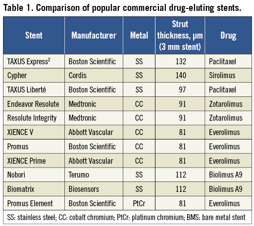
Thin strut bare metal stents have been shown to result in improved outcomes compared to thick strut designs1, with more recent data suggesting the existence of a similar relationship in drug-eluting stents (DES)2,3. Thin-strut stents have the added benefits of increased deliverability and conformability. As a result, modern DES platforms have been designed with much thinner struts than the original TAXUS Express2 (Boston Scientific, Natick, MA, USA) and Cypher (Cordis, Bridgewater, NJ, USA) stents (Table 1). The use of alloys such as cobalt chromium and platinum chromium allows stents to be created with thinner struts than with stainless steel, whilst maintaining strength and radio-opacity.
With the reduction in strut thickness, innovative designs have enabled maintenance of radial strength. However, longitudinal (or axial) strength may be lower with these new designs and is not routinely reported by stent manufacturers. Longitudinal stent deformation can be defined as the distortion or shortening of a stent in the longitudinal axis following successful stent deployment. Hanratty and Walsh recently reported three cases of longitudinal stent deformation in modern generation stents related to guide catheter compression of stents deployed in an ostial location4. We have seen several cases of longitudinal stent deformation in our centre, and report on our experiences describing several additional mechanisms of deformation to those reported by Hanratty and Walsh. We also examine the frequency of stent deformation of the various DES platforms to gain mechanistic insight into the processes that may contribute to this phenomenon and discuss treatment options for this complication.
Methods
Operators at our centre identified possible cases of longitudinal stent deformation which they had experienced over a four year period between September 2007 and September 2011. Case note and angiographic review were performed for all possible cases to ensure longitudinal stent deformation had occurred. Clinical follow-up was available for all patients.
The number of interventional procedures performed and the total number and type of stents deployed during this time period were recorded. The rate of stent deformation was estimated by dividing recorded cases of deformation by the number of implanted stents for each platform during the study period.
Results
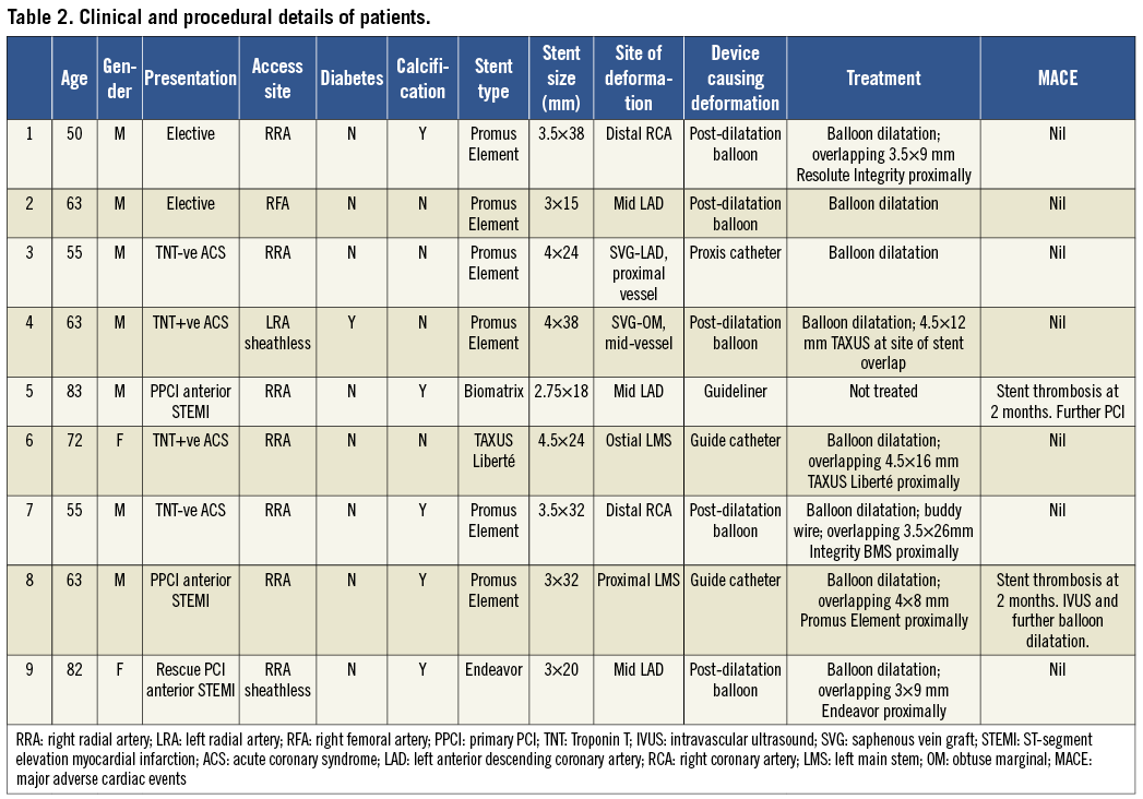
We identified nine patients with definite longitudinal stent deformation during the study period. These cases were performed by six different operators. The clinical and procedural characteristics are shown in Table 2.
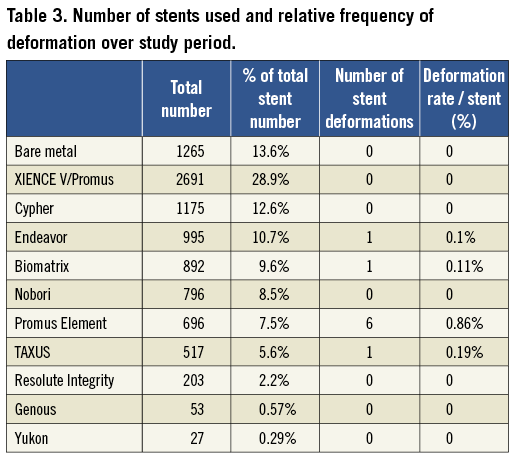
There were 4,455 interventional cases performed during this time period. A total of 9,310 stents were deployed (mean 2.1 stents/procedure) and 82.4% of these were DES. Stent deformation occurred in 0.2% of cases and affected 0.097% of stents deployed. The breakdown of stent types is shown in Table 3. Six cases involved a Promus Element (Boston Scientific, Natick, MA, USA) stent and there was one case each involving an Endeavor (Medtronic, Minneapolis, USA), Biomatrix (Biosensors Interventional Technologies, Singapore) and TAXUS Liberté (Boston Scientific) stent. Stent deformation varied from 0% in several stent types to 0.86% in the case of Promus Element (Boston Scientific) with six stent deformations observed out of 696 stents deployed.
The details of six of the cases are described below.
Case 1: Post-dilatation balloon
A 50-year-old man was admitted for elective percutaneous coronary intervention (PCI) to the distal right coronary artery (RCA). Access was obtained via the right radial artery using a 6 Fr multipurpose (MPA-1) guide catheter. A BMW Universal II (Guidant, Indianapolis, IN, USA) wire was passed to the distal vessel and the lesion was direct stented with a 3.5×38 mm Promus Element stent with normal appearances of the stent architecture following deployment (Figure 1, Panel A). However, a 3.75×15 mm non-compliant balloon would not advance into the stented segment. Subsequently, it was clear angiographically that the proximal stent edge had been deformed at the site where wire bias had caused contact between the tip of the balloon catheter and the stent struts along the outer curve of the vessel (Figure 1, Panel B). Several smaller diameter balloons (down to 1.5mm diameter) would also not advance into the stent, catching at the site of stent deformation. Finally a 0.85×10 mm Schwager balloon (SIS Medical AG, Switzerland) was passed (Figure 1, Panel C) and, following dilatation with this, serial dilatation was performed with 1.1 mm, 1.25 mm, 1.5 mm, 2 mm and 3.5 mm compliant balloons. A short 3.5×9 mm Resolute Integrity (Medtronic) stent was overlapped proximally and final post-dilatation was performed with a 3.75 mm non-compliant balloon. This showed good stent expansion (Figure 1, Panel D). The patient remained well at 4-month clinic follow-up.
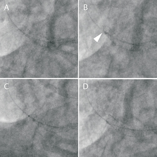
Figure 1. A) A 3.5×38 mm Promus Element stent is deployed in the distal RCA. B) Following unsuccessful attempts to advance a 3.75 mm non-compliant balloon, stent deformation of the proximal stent edge is noted (arrowhead). C) A 0.85 mm Schwager balloon is finally passed. D) Final appearance following serial balloon dilatation and deployment of an overlapping 3.5×9 mm Resolute Integrity stent.
Case 2: Post-dilatation balloon
A 63-year-old man was admitted for elective PCI to the mid-left anterior descending coronary artery (LAD) (Figure 2, Panel A). Access was obtained via the right femoral artery using a 6 Fr XB 3.5 guide catheter. The vessel was wired with a BMW (Guidant) wire and the lesion was pre-dilated with a 3 mm compliant balloon and then stented with a 3×15 mm Promus Element stent with a normal appearance of the stent post deployment (Figure 2, Panel B). A 3.5 mm non-compliant balloon would not advance into the stented segment and it became apparent that the proximal stent edge had been deformed by the balloon where wire bias has caused contact between the tip of the balloon catheter and the stent struts (Figure 2, Panel C). A 2.5 mm balloon was then successfully advanced into the stent and the stent was re-expanded. Final post-dilatation with the 3.5 mm non-compliant balloon produced an excellent result (Figure 2, Panel D).
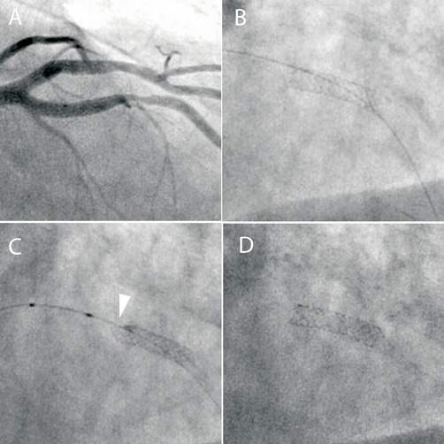
Figure 2. A) Angiographic appearance of a severe mid-LAD lesion. B) A 3×15 mm Promus Element stent following deployment. C) Following unsuccessful attempts to advance a 3.5 mm non-compliant balloon, stent deformation of the proximal stent edge is noted (arrowhead). D) Final appearance following compliant and non-compliant balloon dilatation.
Case 3: Proximal embolic protection catheter
A 55-year-old man with previous coronary artery bypass grafting (CABG) was admitted with an acute coronary syndrome. Diagnostic angiography via the right radial artery demonstrated critical disease within a vein graft supplying the LAD with only TIMI 2 flow distally. A 6 Fr LCB guide catheter was used and a ChoICE Floppy wire (Boston Scientific) was passed down the graft to the native LAD. A 6 Fr Proxis device (St. Jude Medical, St. Paul, MN, USA) was placed in the proximal graft for embolic protection. The graft was pre-dilated and then stented with a 4×38 mm Promus Element that was overlapped proximally with a 4×24 mm Promus Element, both deployed at 14 atmospheres (Figure 3, Panel A). On withdrawal of the stent balloon, the Proxis catheter (with its occlusion balloon deflated) was pulled in and deeply engaged the graft into the stented segment. Subsequent angiography showed severe deformation of the proximal stent edge (Figure 3, Panel B). It proved impossible to pass either a 2.5 mm or 2 mm balloon into the stent. Finally, a 1.5 mm balloon was passed (Figure 3, Panel C) and inflated and serial dilatation was performed with 2 mm, 2.25 mm, 2.5 mm compliant balloons and a 4.5 mm non-compliant balloon. This resulted in full expansion of the stent although the stent was shortened and the proximal edge was more radio-opaque as a result of crowding of the struts (Figure 3, Panel D). The patient was well at 4-month clinic follow-up.
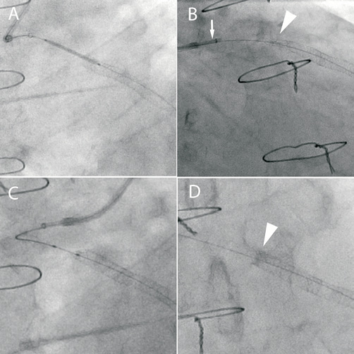
Figure 3. A) A 4×24 mm Promus Element stent is positioned overlapping a previously deployed stent in a vein graft to the LAD. A Proxis catheter is used for proximal embolic protection. B) During withdrawal of the stent balloon, the Proxis catheter (arrow) deeply engaged the graft causing severe deformation of the proximal stent edge (arrowhead). C) Serial balloon dilatation of the deformed proximal stent edge. D) Final result following balloon dilatation. Note the increased radio-opacity at the proximal stent edge due to strut crowding (arrow).
Case 4: Distal crush
A 63-year-old man with a previous CABG presented with an acute coronary syndrome. Re-opening of an acutely occluded obtuse marginal vein graft was attempted. This was approached via a 7.5 Fr sheathless JR4 guide catheter (Asahi Intecc Co, Japan) from the left radial artery. A BMW wire was successfully passed through the occlusion into the native vessel. Thrombectomy was performed and a Proxis device was deployed in the proximal graft to minimise embolisation associated with stent deployment. Two overlapping 4×38 mm Promus Element stents were implanted (Figure 4, Panel A). Post-dilatation of the distal stent was performed with a 4.5x20 mm non-compliant balloon whilst the Proxis device was inflated in the proximal portion of the stented segment. On attempting to remove the deflated balloon, mild resistance was encountered and so angiography was performed. This showed severe deformation of the stents at a point of angulation proximal to the balloon (Figure 4, Panel B). Following balloon removal, the area of deformation was dilated with 3 mm and 4 mm compliant balloons and a 4.5 mm non-compliant balloon which re-expanded the stent (Figure 4, Panel C). However, when the deflated 4.5 mm balloon was withdrawn, severe deformation of the stents at the site of vessel angulation was again observed (Figure 4, Panel D). It was thought that traction of the large deflated balloon on the stent struts at the point of angulation, with the guide catheter unable to move in due to the inflated Proxis device, had led to longitudinal stent crush with the associated deformation. The area of deformation was therefore dilated again and then re-stented with a TAXUS Liberté 4.5×12 mm stent to improve longitudinal strength (Figure 4, Panel E). Further post-dilatation of the distal segment without the Proxis device was uncomplicated with an excellent angiographic result (Figure 4, Panel F).
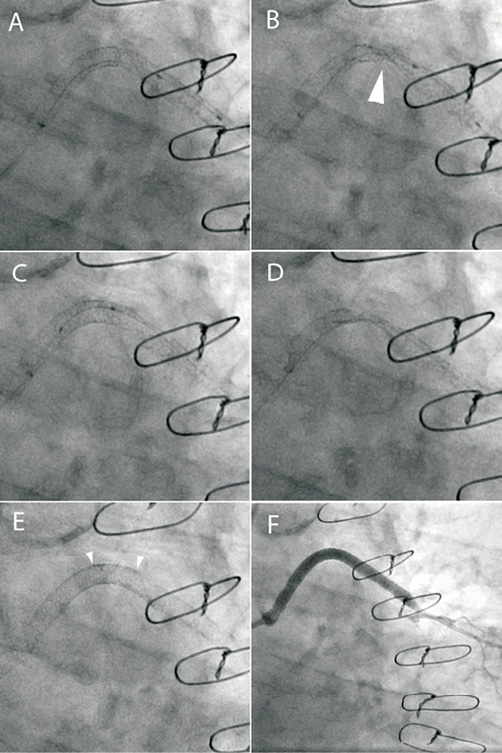
Figure 4. A) Two overlapping 4×38 mm Promus Element stents are implanted into a vein graft to obtuse marginal. B) Following withdrawal of the post-dilatation non-compliant balloon with the Proxis catheter balloon inflated there is severe disruption of the stented segment (arrow). C) The stent is re-expanded with serial balloon dilatation. D) During withdrawal of the non-compliant balloon there is again severe stent deformation. E) A TAXUS 4.5×12 mm stent is deployed at the area of deformation to increase longitudinal strength (arrowheads). F: Final angiographic result.
Case 5: Guide catheter extension
An 83-year-old man with an anterior ST-elevation myocardial infarction (STEMI) was transferred directly to the catheter laboratory for primary PCI. Access was obtained via the right radial artery and a 6 Fr XB3 guide catheter. Restoration of flow to an occluded LAD was achieved using thrombectomy and balloon dilatation. This revealed diffuse, calcific disease of the proximal and mid-LAD that was treated by deploying a 2.5×36 mm Biomatrix stent overlapping with a 2.75×18 mm Biomatix stent proximally (Figure 5, Panel A). Stent deployment was complicated by slow reflow that was successfully treated with intra-coronary vasodilator therapy. This was delivered directly into the LAD using a Guideliner catheter extension (Vascular Solutions, Inc. Minneapolis, USA) (Figure 5, Panel B). Contact between the Guideliner catheter and the proximal edge of the stent caused minor deformation and shortening of the proximal stent edge that was accepted with a good angiographic result (Figure 5, Panel C).
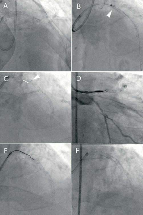
Figure 5. A) Following LAD opening during primary PCI for an anterior STEMI, two overlapping Biomatrix stents are deployed. B) A Guideliner catheter extension is used to deliver intracoronary vasodilators for “no reflow” (arrowhead). C) This resulted in stent compression (arrowhead) and shortening (arrow) but there was TIMI 3 flow and this result was accepted. D) Re-presentation with acute stent thrombosis with occlusion at the proximal stent edge. E) Wiring the deformed stent inlet proved very difficult. F) Final result after serial dilatation and deployment of an overlapping 3×24 mm Promus Element stent.
Seven weeks later the patient re-presented with a further anterior STEMI and was taken directly to the catheter laboratory. He had maintained good compliance with dual antiplatelet therapy of aspirin and prasugrel. An intra-aortic balloon pump was inserted as there was haemodynamic compromise. Angiography demonstrated occlusion of the LAD stent consistent with late stent thrombosis (Figure 5, Panel D). It was apparent that the stent inlet was deformed, and it proved impossible to enter the stent with a BMW Universal II wire (Figure 5, Panel E), but eventually a Whisper wire (Abbott Vascular, Santa Clara, CA, USA) was negotiated into the distal LAD. The stent inlet was dilated with a 2.75 mm balloon and thrombectomy was performed which restored flow. A 3×24 mm Promus Element stent was deployed proximally overlapping the previously deployed stents. Further dilatation of the proximal stent was performed with a 3 mm non-compliant balloon with an excellent angiographic result (Figure 5, Panel F).
Case 6: Guide catheter
A 72-year-old woman was admitted with an acute coronary syndrome. Coronary angiography performed via the right radial artery showed a long highly angulated left main stem (LMS) and an ostially occluded small circumflex. A 6 Fr XB3.5 guide catheter was used and during attempts to pass a guidewire into the circumflex the left main stem was dissected (Figure 6, Panel A). A 4.5×24 mm TAXUS Liberté was deployed back to the ostium of the left main stem and then an overlapping 3.5×16 mm Promus Element stent was placed distally (Figure 6, Panel B). At this point there was deep engagement of the guide catheter and crushing of the proximal stent (Figure 6, Panel C). As a result, the stented segment was shortened in length by 5 mm (Figure 6, Panel D). The stent was dilated with a 4 mm compliant and 4.5 mm non-compliant balloon and then an overlapping 4.5×16 mm TAXUS Liberté was deployed back to the LMS ostium (Figure 6, Panel E). The final result was excellent (Figure 6, Panel F). Diagnostic angiography performed at six months showed no evidence of in-stent restenosis and the patient remains well at follow-up.
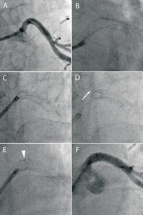
Figure 6. A) The LMS is dissected during attempted PCI of an occluded circumflex artery. B) A 4.5×24 mm TAXUS Liberté is deployed back to the ostium of the LMS. C) There is deep engagement of the guide catheter causing stent deformation. D) There is approximately 5 mm of shortening of the stented segment (arrow). E) An overlapping 3.5×16 mm TAXUS Liberté stent is deployed back to the ostium. F) Final angiographic result.
Three other cases of stent deformation were identified and are summarised in Table 2 with the underlying mechanism of stent deformation highlighted.
Discussion
This case series extends the initial report of Hanratty and Walsh on longitudinal stent deformation4. These authors reported three cases, all of which occurred in ostial stents. Two cases occurred due to guide catheter compression of the proximal stent edge. The third case involved a LMS stent which was deformed at both ends: distally secondary to an intravascular ultrasound (IVUS) catheter and proximally secondary to guide catheter compression. This current report identifies several other mechanisms through which stent deformation may occur in addition to those described by Hanratty and Walsh and we provide further data on the frequency of occurrence of stent deformation of the various DES platforms which may provide mechanistic insight into this previously unrecognised complication. Finally, the current report discusses a systematic approach to the treatment of this complication.
In this series, we identified nine cases of stent deformation at our centre over a four year period. The cases occurred with six different operators making it unlikely to be solely due to procedural technique. Unlike the cases described by Hanratty and Walsh, all cases were readily identifiable angiographically. Similar to their report, we describe two cases of ostial stents crushed by the guide catheter, but we also describe seven cases where stent deformation occurred by alternative mechanisms. Two stents were crushed by guide catheter extensions (Proxis and Guideliner), and five stents were crushed by uninflated balloons –to the best of our knowledge this is the first such report of these complications in the literature.
Whilst it can be appreciated that a guide catheter, or indeed a guide catheter extension, can apply significant force to an unapposed proximal stent, we view the cases in which uninflated balloons have caused stent deformation as unexpected and concerning. Furthermore, once deformation has occurred, subsequent balloon advancement may be extremely difficult, requiring careful introduction of very small diameter balloons, gradually building up to larger diameter balloons with extreme care not to crush the stent further if balloons fail to enter the deformed segment. This involved using an 0.85 mm balloon to enter a 3.5 mm stent in case 1 after a 1.5 mm balloon failed to enter the deformed stent.
In four cases, the mechanism by which post-dilatation balloons caused stent crush was by wire bias causing contact between the tip of the balloon catheter and the proximal stent edge along the outer curve of bend (Figure 7; illustrated in cases 1 and 2). Although not evident angiographically in these cases, the stent edge may not have been fully embedded into the vessel wall at this point. In a further case, traction of a deflated balloon at a point of angulation mid-stent in a vein graft caused deformation. Force transmission to the stent was thought to be related to fixation of the guide catheter by an inflated Proxis device preventing the guide catheter being pulled in to the vessel. In this case, the poor support that a vein graft wall offers to a deployed stent, in contrast to a more rigid coronary artery, may have also contributed.
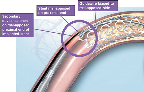
Figure 7. Diagram demonstrating mechanism of proximal stent edge deformation by balloon catheter or other device, as a result of guidewire bias. Illustration for information purposes, not indicative of actual size or clinical outcome. © 2011 Boston Scientific Corporation or its affiliates. All rights reserved. Used with permission of Boston Scientific Corporation.
The importance of treating longitudinal stent deformation is exemplified in case 5 in which stent crush at the end of the index procedure was thought to be related to subsequent stent thrombosis associated with a concentrated mass of unapposed stent struts. In addition, the difficulties encountered re-wiring the crushed stent can be appreciated as re-wiring may frequently involve wire passage through lifted struts rather than through the centre of the stent. It is therefore important to recognise the complication before wire removal. The good medium term outcome of the cases in which stent crush was recognised and treated is reassuring.
We have likely significantly underestimated the true number of cases of longitudinal stent deformation. Firstly, this complication has only very recently become appreciated and is likely to have been under-diagnosed as a result. Identification of the cases relied on operators diagnosing the complication and recalling the details of the case. This may have been more incomplete at the start rather than at the end of this series, possibly under-representing the incidence associated with first generation DES. In addition, stent deformation may be difficult to detect angiographically, as illustrated in case 5, in which stent crush only became evident at the time of re-presentation due to stent thrombosis. Similarly, in one of the cases described by Hanratty and Walsh, stent deformation visible on IVUS was not detected angiographically. Adjunctive imaging with IVUS or optical coherence tomography (OCT) was not performed in any of the cases in this series; all involved significant stent deformation and attempting to pass a bulky IVUS or OCT catheter would likely have resulted in further stent distortion.
Although numbers are small, longitudinal deformation occurred most frequently with the Promus Element stent in this series. The rate of stent deformation was observed in nearly 1% of Promus Element stents deployed (0.86%), compared to 0.1-0.2% with other platforms, and no cases associated with the XIENCE V/Promus or Cypher stents were identified which were the most commonly used stents at our centre during the study period. The difference in stent deformation incidence observed across the different stent platforms may provide mechanistic insight into the processes that contribute to the phenomenon, and in particular aspects of stent design that may predispose to this complication. The Promus Element stent, has a thin strut, open cell design leading to marked flexibility, conformability and deliverability5. However, such a design may contribute to reduced longitudinal rigidity increasing the risk of deformation. Pseudofracture of the Endeavor Micro Driver stent with wide separation of struts (i.e., loss of longitudinal integrity) is perhaps a related phenomenon, also seen with a very open cell stent design6. Interestingly, the other case in which a stent was crushed at the point of entry of a post-dilation balloon occurred with an Endeavor stent. It is possible that the increased radio-opacity of the platinum chromium Promus Element stent, as compared to other DES, may partly explain the increased frequency of deformation observed. However, this was not detected previously with platforms such as Cypher, that are also relatively radio-opaque. In addition, several cases involving the Promus Element stent were identified because of an inability to enter the stent with a post-dilatation balloon, which would have been noted by the operator even if stent deformation was not detected (cases 1, 2, 3 and 7), and two of the cases (cases 3 and 4) involved such severe stent deformation that the whole vessel appeared collapsed at this point.
In conclusion, longitudinal stent deformation can occur secondary to a variety of mechanisms and identification is important as, left untreated, it may be associated with a risk of stent thrombosis. Care needs to be taken if there is any resistance to passage of post-dilatation balloons and in ostial lesions, where the guide catheter or guide catheter extensions may contact the stent. Stent crush is more likely to occur when stents are incompletely apposed to the vessel wall and may be more common in vein graft interventions due to the poor support to the stent offered by the wall of the vein graft. Although seen with several different stents, in this small retrospective series it was more commonly observed with the Promus Element stent. We concur with Hanratty and Walsh that stent manufacturers should develop a standardised method of measuring longitudinal stent strength and tests to determine the likelihood of its occurrence involving both contact with guide and extension catheters and entry by balloon catheters.
Conflict of interest statement
D.G. Fraser and F. Fath-Ordoubadi have served as advisory board members and /or have received consulting fees for Boston Scientific and Terumo, and have received speaker fees from Cordis. All other authors have no conflicts of interest to declare.