Abstract
Aims: There have been recently reported clinical observations of significant longitudinal compression or “stent shortening” in certain contemporary drug-eluting stents (DES), when re-crossed with other devices such as post-dilatation balloons, stent delivery systems or intravascular ultrasound (IVUS) catheters. The aim of this study was to understand the effect of stent design on longitudinal compression for coronary stents, when subjected to certain forces in vitro. This goal was achieved by experimentally evaluating the longitudinal strength of 14 contemporary stent designs under a clinically relevant compression force using a bench test method developed for this purpose. The results from the study are intended to provide an indication whether there is a quantifiable difference in the ability of the different stent platform designs to resist longitudinal compression in a deployed configuration.
Methods and results: A test method was developed to evaluate the longitudinal compression behaviour of coronary stents. The test method was used to compare the longitudinal compression of four stent design families including a total of 14 commercialised stent platforms under a clinically relevant longitudinal compression force. The nominal expansion diameter of stents used in this study was 3.0 mm with stent lengths ranging from 28-30 mm. A test method was also developed to estimate a value of the clinically relevant longitudinal compression force to which a deployed stent may be subjected in a situation when a catheter tip is caught while trying to cross a freshly deployed stent. That force was determined to be 50 gram force (gf) (0.49 N). Based on the results of the testing it was noted that three of the four design families (13 of the 14 stents tested) demonstrated a longitudinal compression in the range of 1.25-5.30 mm (longitudinal compression of 4.46%-18.93% compared to the nominal expanded stent length), with the exception of the offset peak-to-peak stent platform having results clearly outside of this grouping. The stent in the offset peak-to-peak design category (Element stent platform) had an average longitudinal compression of 13.20 mm (longitudinal compression of 47.07%), thus demonstrating a markedly lower resistance to longitudinal compression.
Conclusions: Stent design is a primary driver determining the longitudinal compression behaviour of coronary stent platforms. The results of this study comparing the longitudinal compression performance of four different commercial stent design families indicate that the tendency of a deployed stent to undergo longitudinal compression is associated with the stent design concept. It was determined that the particular 2-link offset peak-to-peak design evaluated in this study had the lowest compression resistance compared to the other stent design families.
Introduction
Since the commercialisation of the first coronary stent, stent manufacturers have been working to continually improve the acute and long-term performance of stent designs. This improvement in performance has been achieved through the development of advanced stent designs and the use of new materials in their design. The advent of drug-eluting stents (DES) resulted in further improvement in long-term event rates associated with restenosis, target lesion revascularisation (TLR) and target vessel failure (TVF). Even though DES have been successful in improving the safety and efficacy of revascularisation procedures, in order to further improve acute and long term clinical performance, the focus has once again shifted to stent design. As advanced designs are being developed, it should be kept in mind that stent design is a balancing act of several performance attributes such as crimped and expanded stent flexibility, shortening upon expansion, trackability, scaffolding, radiopacity longitudinal strength, radial strength and recoil. Care should be taken to ensure that in enhancing one particular stent attribute, other key stent attributes are not negatively affected in a clinically unacceptable way.
Recently, researchers and clinicians have identified longitudinal compression or post-deployment stent shortening as a new failure mode not previously observed in coronary stents.1-3 This phenomenon consists of the deployed stent shortening dramatically due to the stent rings coming close to each other and nesting or overlapping onto each other when subjected to a longitudinal compression force. This shortening usually occurs when the clinician attempts to cross the stent placed in an artery with other devices such as post-dilatation balloons, stent delivery systems or intravascular ultrasound (IVUS) catheters.
This paper presents the results of an investigation of the longitudinal compression behaviour of the four contemporary coronary stent design families using elaborate bench test methods.
Materials and methods
Stent designs evaluated for longitudinal compression
Abbott Vascular evaluated the longitudinal compression behaviour of the four stent design families by testing 14 commercially available metallic balloon expandable coronary stents. The researchers determined that the stent designs can be classified into four different families based on the manner in which two adjacent rings of a stent are oriented and connected to each other. The four stent design families are (1) in-phase, also known as peak-to-valley, (2) out-of-phase, also known as peak-to-peak, (3) mid-strut connector, and (4) offset peak-to-peak. Figure 1 provides an example and description of each of these stent families.
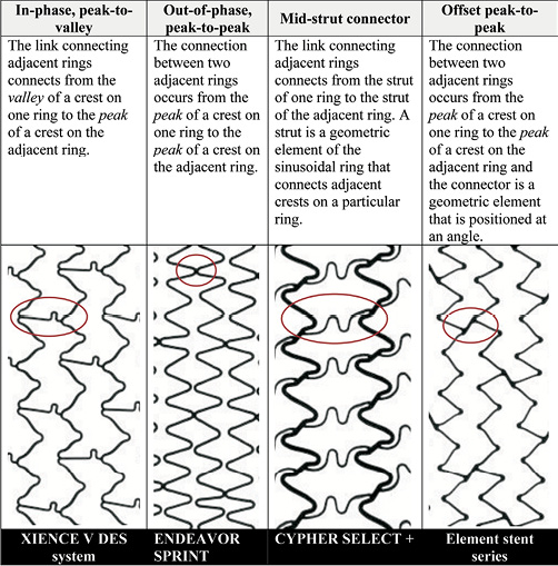
Figure 1. Description of stent families.
When available, the bare metal stent (BMS) version of the product was used to conduct the testing. The results are expected to apply to the drug-eluting versions of the stents as the presence of the drug coating will have negligible influence on the longitudinal compression behaviour of the stent. Table 1 lists the stent designs evaluated in this study. MULTI-LINK VISION is the BMS version of the XIENCE V DES System (Abbott Vascular, Santa Clara, CA, USA) and the MULTI-LINK 8 is the BMS version of the XIENCE PRIME DES System (Abbott Vascular). The Omega stent is the BMS version of the Promus Element and Taxus Element (known as Ion in the US) DES (Boston Scientific, Natick, MA, USA). Further, the BMS versions of Taxus Express (i.e., Express2), Taxus Liberté (i.e., Liberté) (Boston Scientific), Endeavor Sprint (i.e., Driver) (Medtronic, Minneapolis, MN, USA) and Resolute Integrity (i.e., Integrity) (Medtronic) were used in this study. In all other cases, the DES versions of the stents were used. Throughout the remainder of the paper, the stents will be referred to by the DES product name. Figure 2 shows the footprint images of each of the stent designs tested and classifies them as (1) peak-to-valley/in-phase, (2) peak-to-peak/out-of-phase, (3) mid-strut connector or (4) offset peak-to-peak. All stent designs were evaluated at the 3.0 mm diameter (nominal expansion). Since most products are available in the 28 mm length, the 3.0×28 mm size was selected. Some products are not offered in the 28 mm length, so the 29 mm and 30 mm lengths were evaluated (3.0×29 mm Firebird2 [MicroPort Medical Co., Ltd., Shanghai, P.R.China], 3.0×30 mm Endeavor Sprint [Medtronic], 3.0×30 mm Integrity [Medtronic], 3.0×30 mm Coroflex Blue [B. Braun, Melsungen, Germany]).
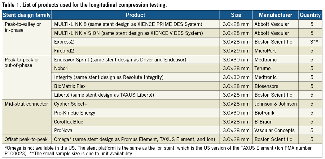
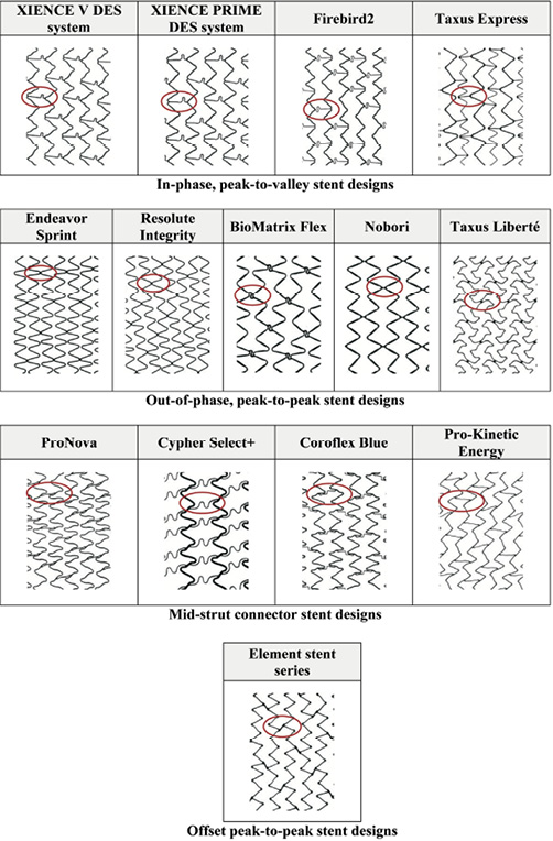
Figure 2. Stent designs evaluated for the longitudinal compression behaviour and their classification into four different families.
Longitudinal compression test method
A test method was developed to evaluate the longitudinal compression behaviour of coronary stents. This test method can be used to characterise the resistance of a stent to longitudinal compression. Prior to being subjected to longitudinal compression, the stents were expanded to the approximate nominal diameter of 3.0 mm in accordance with their compliance chart. Each stent was placed on the mandrel of a test fixture mounted on an Instron mechanical testing system (refer to Figure 3A for a close-up image of the test fixture with a stent mounted on the mandrel) and was compressed by 14 mm. The longitudinal compression force was measured as a function of the compression distance and a plot of the longitudinal compression force versus amount of longitudinal compression was generated. Figure 3B shows a close-up of test fixture after compression of a stent by 14 mm. The testing procedure was repeated for each of the 14 commercialised stent designs using a sample size of n=5 stents per design.
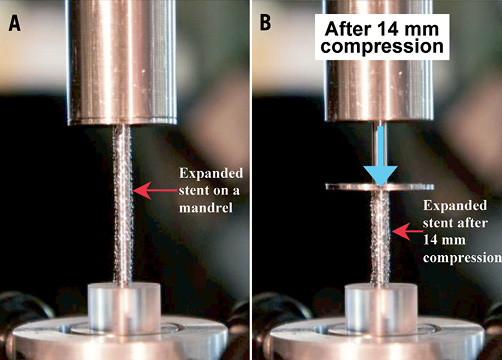
Figure 3. Close-up view of the longitudinal compression fixture with A, the stent placed on the mandrel and B, after longitudinal compression of the stent
Determination of clinically relevant longitudinal compression force
In order to evaluate the extent of longitudinal compression of a stent under a longitudinal compression force, a clinically relevant value of this force is required. The amount of longitudinal compression for the different stent designs should be compared at this force value. A test method using a simulated arterial model was developed to estimate a value of the clinically relevant force. The intent of this test method was to measure the amount of force that an interventional cardiologist could reasonably use when crossing through the deployed stent with a post-dilatation balloon catheter. Figure 4 shows the test system developed to measure this clinically relevant force. The system consists of a synthetic arterial model that includes an aorta with a coronary artery emanating from it and a constriction in the artery to simulate the tip of a balloon catheter catching on an implanted coronary stent. The constriction is connected to a force transducer which measures the amount of applied longitudinal force. A BMW Universal II guidewire (manufactured by Abbott Vascular) was introduced into the artery through a guide catheter and passed through the constriction. A Voyager NC post-dilatation balloon catheter (manufactured by Abbott Vascular) was introduced over the guidewire and the distal tip was pushed against the constriction. Two interventional cardiologists were asked to push the balloon dilatation catheter against the constriction with the force that they would generally apply in a clinical situation when a catheter tip is caught while trying to cross a freshly deployed stent. Each of the cardiologists was asked to repeat the experiment three times. This testing was performed using 6 Fr and 7 Fr guide catheters. The average force applied using the 6 Fr guide catheter was 45±12.5 gf and the average force applied using the 7 Fr guide catheter was 57±12.4 gf. A clinically relevant force of 50 gf was chosen to encompass both clinical scenarios. The longitudinal compression behaviour of all the stents were compared at this force value of 50 gf.
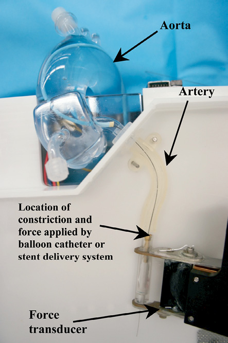
Figure 4. Test fixture used to measure an estimate of the clinical relevant compression force.
Results
From the data generated using the longitudinal compression test method, the amount of longitudinal compression for each sample of a particular stent design was determined at a load of 50 gf. Table 2 lists the average longitudinal compression under the applied force of 50 gf for each of the 14 stent designs tested. In addition to the average, the table also lists the standard deviation, the minimum, and the maximum longitudinal compression measured for each stent design. Figure 5 illustrates the average longitudinal compression at 50 gf for the 14 stent designs tested. Also, shown in Figure 5 are the strut thicknesses and materials used for the 14 stent designs. Figure 6 shows a plot of the longitudinal compression distance versus longitudinal force extracted from the test data. The plot shows the amount of longitudinal compression for each stent platform as applied longitudinal force values ranging from 0 to 60 gf.
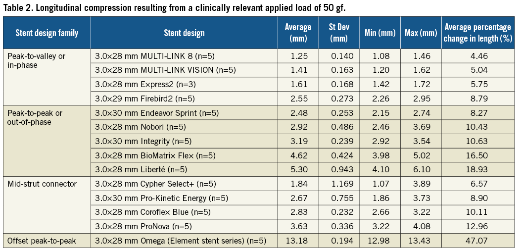
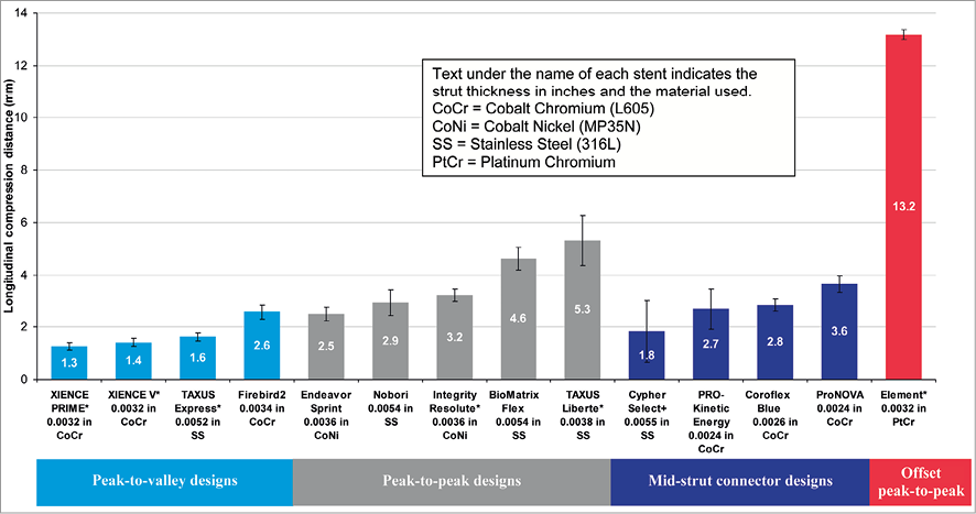
Figure 5. Longitudinal compression under a clinically relevant force of 50 gf (*bare metal versions of these platforms were used for testing)
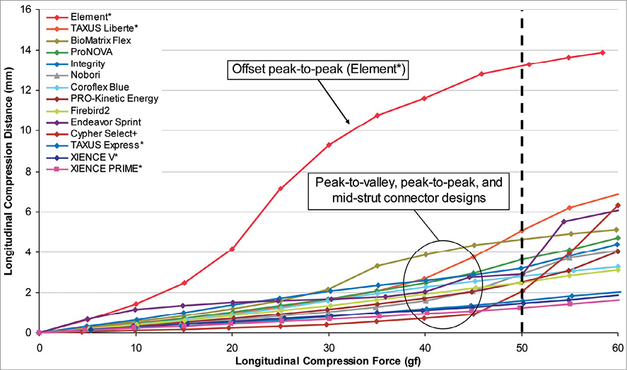
Figure 6. Plot of amount of longitudinal compression versus longitudinal compression force (*bare metal versions of these platforms were used for testing)
For most of the stents tested, under a longitudinal compression force of 50 gf and at the nominal expansion diameter of 3.0 mm, the average longitudinal compression varied from 1.25 mm (4.46% of nominal expanded stent length of 28 mm) for the lowest of the peak-to-valley designs (XIENCE PRIME DES system) to 5.3 mm (18.93% of the nominal expanded stent length of 28 mm) for the highest of peak-to-peak designs (TAXUS Liberté), with the exception being the offset peak-to-peak design (the Element stent series which includes the Promus Element and TAXUS Element [known as Ion in the US] DES and Omega BMS). The offset peak-to-peak design was highly differentiated from the rest of the tested stent designs in its ability to resist longitudinal compression with an average longitudinal compression of 13.20 mm (47.07% of the expanded stent length of 28 mm) under the compression force of 50 gf.
Discussion
In a clinical setting, examples of situations in which a deployed stent can be subjected to longitudinal force include (1) IVUS pull-back during post-deployment inspection of the deployed stent, (2) withdrawal of a stent delivery system when the balloon gets caught in struts of the deployed stent, (3) crossing of a newly deployed stent with a stent delivery system for treatment of a distal lesion, (4) crossing of a balloon dilatation catheter through a deployed stent for post-dilation of the stent, and (5) guide catheter contact with the stent after stent deployment due to ostial location or deep-seating of the guide. While these are just some examples of situations in which a stent can experience a longitudinal compression loading, there are potentially a number of other situations where a deployed stent can experience such a loading condition. Further, malapposition of the stent struts to the vessel wall can also accentuate the situation as it provides an edge for the system used in the post-deployment interventional procedure (such as an IVUS catheter, balloon dilatation catheter or a stent delivery system) to more easily get caught and apply a longitudinal compression force to the stent.
Based on these data generated from various designs, strut thicknesses and materials, only stent design plays a critical role in determining the longitudinal strength of a stent and to a large extent determines the compression resistance of a stent. A review of the stent designs tested and the data from the bench testing suggests that the main cause for the longitudinal compression is the nesting of stent rings into and over each other upon the application of a longitudinal force. The stent design(s) that can inherently undergo nesting of the rings upon application of a longitudinal force on a deployed stent appear to be more likely to demonstrate this effect. Figure 7 illustrates the effect of stent design configuration on the compression resistance of a stent design. For the in-phase or peak-to-valley designs, all of which have three links connecting adjacent rings, the long links connecting two adjacent rings are oriented along the longitudinal axis of the stent and therefore, provide the stent with the required column strength while preventing the rings from nesting into each other. As can be noted from Table 2, stent designs with this configuration generally demonstrated the highest resistance to longitudinal compression, indicated by the fact that they generally experienced lower amounts of longitudinal compression under the application of the 50 gf force. For the out-of-phase or peak-to-peak designs (most designs evaluated have two links connecting adjacent rings, with the exception of Taxus Liberté with three links), upon application of the longitudinal force, the crests from the adjacent rings come in contact with each other and thus, resist longitudinal compression. For the mid-strut connectors (most designs evaluated have three links per ring with the exception of Cypher Select+ with six links), the longer struts connect the middle of the bar-arms of two adjacent stent rings and provide the required resistance to longitudinal compression. The offset peak-to-peak design with two links connecting adjacent rings, has short angled links as illustrated in Figure 7. These links cause crests from two adjacent rings to be offset from each other. Based on this testing, when a longitudinal compression force is applied to the stent with this offset peak-to-peak configuration, the stent rings nest within each other resulting in significant longitudinal compression or shortening as shown in Figure 5. Moreover, even at force values higher and lower than 50 gf, the offset peak-to-peak stent experienced substantially higher longitudinal compression compared to the other stent families as shown in Figure 6.
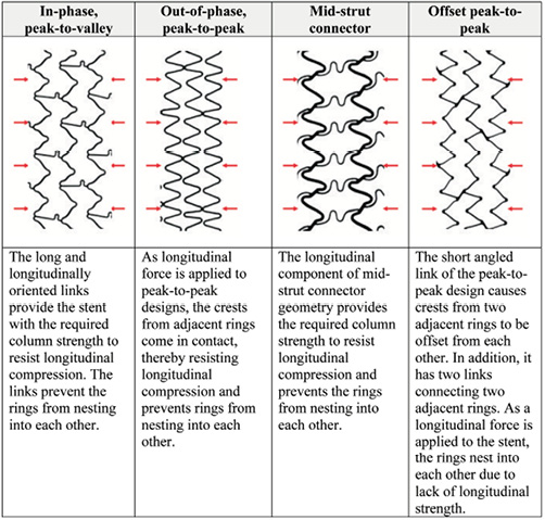
Figure 7. Compression resistance of stent design families.
The thickness of the struts for the different stent designs tested along with the stent materials used in developing these stent platforms are indicated in Figure 5. From the data, it was noted that there is no apparent correlation between the amount of longitudinal compression and the stent strut thickness (correlation coefficient, r =–0.10). Further, it was also determined that there was a moderate correlation between the amount of longitudinal compression and the number of links (correlation coefficient, r=–0.35). As far as stainless steel, cobalt chromium and cobalt nickel are concerned there seems to be no clear correlation between longitudinal compression behaviour and stent material. However, further research is needed to understand the correlation between longitudinal compression and the platinum chromium alloy.
In this paper, the researchers focused on the attribute of longitudinal stent compression. However, in the case of a stent design that has relatively low longitudinal strength under elongation, the stent rings can also undergo major deformation or separation under elongation forces. Other researchers have commented that this gives the appearance of stent fractures under angiography. This phenomenon has been termed “pseudo fractures” and has been reported by Pitney et al.4
Limitations
The test method described in this paper is used to compare the longitudinal compression behaviour of 14 commercialised stent designs. In this test method, the longitudinal compression force is applied to one end of the stent. This does not specifically simulate the situation where devices such as balloon dilatation catheters, stent delivery systems or IVUS catheters get caught on stent struts and apply a localised force. Also, the stents are tested in an unconstrained manner and could potentially have different amounts of longitudinal compression as compared to stents that are deployed in arteries. As with many engineering test methods, this particular test set-up was not intended to exactly replicate a clinical situation, but to isolate a particular design attribute being investigated. While it is impossible to replicate every possible clinical situation, the purpose of this test method was to provide an understanding of the comparative response of the different stent designs to longitudinal compression forces using the same loading method. The researchers believe that any stent that is an outlier using this test method will likely demonstrate similar behaviour in a clinical situation.
Conclusion
Stent design plays a major role in determining the longitudinal compression behaviour of stents. Three of the four stent design families evaluated in this study were in the relatively narrow compression range of 1.25 mm to 5.30 mm (longitudinal compression of 4.46% to 18.93% compared the nominal expanded stent length). These stents belong to the peak-to-peak, peak-to-valley or mid-strut connect stent configurations with two to six links connecting adjacent rings, depending on the design. However, the 2-link offset peak-to-peak design demonstrated the lowest resistance to longitudinal compression by shortening 13.20 mm (longitudinal compression of 47.07% compared to the nominal expanded stent length). These results support the conclusion that the tendency for a stent to undergo longitudinal compression or shortening under a longitudinal compression force is not an issue with newer stents with thinner struts, but specific to this particular offset peak-to-peak stent design.
Conflict of interest statement
Santosh Prabhu, Tanya Schikorr, Tamer Mahmoud, James Jacobs and Adriaan Potgieter and Charles Simonton are employees of Abbott Vascular.