- stent strut apposition
- stent induced wall stresses
- finite element analysis
Abstract
Aims: The aim of this study was to compare the stent strut apposition and stent induced vessel wall stresses of currently used coronary stent designs. This may help to better understand their clinical performance and provide the insights necessary for further optimisation.
Methods and results: We compared the stent strut apposition of six different stent designs when deployed (at 12 atm) in an idealised stenosed vessel using a novel approach based on finite element simulations. Additional insights into the mechanical behaviour of the investigated stents were obtained by virtually quantifying the stent induced vessel wall stresses. For the investigated stenosed vessel model, the percentage of malapposed struts (distance to wall > 10µm) ranged between 9% (Integrity stent) and 43% (Promus Element stent). The largest strut-artery distances were observed at the plaque shoulders. The 95 percentile of the axial stress within the intima ranges from 32 (Promus Element stent) to 83 kPa (Liberté stent). Stress peaks were mainly located at the inner curvatures of the vessel model and at the stent ends.
Conclusions: For the investigated case, considerable differences were observed between the studied stent platforms in terms of stent strut apposition and stent induced vessel wall stresses. These differences in mechanical behaviour may help to explain clinical observations.
Abbreviations
BMS bare metal stent
DES drug-eluting stent
ISA incomplete stent apposition
IVUS intravascular ultrasound
OCT optical coherence tomography
CT computed tomography
MLA minimal luminal area
MLD minimal luminal diameter
Introduction
The design of bare metal stents (BMS) clearly influences the immediate and long-term clinical outcome as shown by Kastrati et al1. They compared five different uncoated stents of the same material during a randomised trial and ascribed the significant differences in event-free survival at 1-year (ranging from 69.2% to 82.4%) to differences in stent design. The role of the design became less clear after the introduction of drug-eluting stents (DES). These devices consist of multiple components (coating, drug and design) which makes it more complicated to assess the impact of one individual factor. The fact that all DES lead to low restenosis rates, with small differences between the available products2, also contributed to the reduced attention given to the design. However, research focusing on the design of stents remains justified because a further improvement of the clinical outcomes will only be achieved through further optimisation of both the drug delivery system and the underlying platform.
Many different stents are currently available on the market and the differences between the designs of these products are not always clear. Objective comparisons may help to better understand the clinical performance of the available products and may also provide the insights necessary for further optimisation. We therefore evaluated the mechanical behaviour of six different stent platforms in terms of stent strut apposition and stent induced vessel wall stresses.
Incomplete stent apposition (ISA) or stent malapposition is the lack of contact between stent struts and the underlying arterial wall. ISA has been associated with significantly higher levels of thrombus deposition3, but little is known about the role of the stent platform. In this paper, we propose a novel method based on advanced computer (i.e., finite element) simulations to investigate the phenomenon of ISA. The proposed approach allows quantification and visualisation of ISA over the complete stent length, in contrast to the currently used ISA measurement procedures that use intravascular ultrasound (IVUS)4 or optical coherence tomography (OCT)5 cross-sectional images. It should be feasible, however, to perform similar 3D analysis and visualisation of ISA over the complete stent length using 3D OCT reconstructions, although such analysis has not yet been reported.
Stent induced vessel wall stresses were also quantified for the six different stent designs using a similar computational approach. These stresses should ideally be low as it has been suggested that high stresses cause vessel injury and may act as a chronic stimulus for cell proliferation6.
Materials and methods
Stents
The following stents were evaluated in this study: (i) Integrity stent (Medtronic, Minneapolis, MN, USA), (ii) Liberté or Veriflex stent (Boston Scientific, Natick, MA, USA), (iii) Multi-Link 8 stent (Abbott Vascular, Santa Clara, CA, USA) (iv) Multi-Link Vision stent (Abbott Vascular), (v) Pro-Kinetic Energy stent (Biotronik, Bülach, Switzerland), (vi) Promus Element stent (Boston Scientific). Table1 contains information on the stent dimensions and alloys and links the investigated BMS to their corresponding drug-eluting version (and vice versa).
One sample of each stent was scanned in its crimped state at two different resolutions. All scans were performed using a Nikon XT H 225 CT system which consists of a Nikon open type X-ray tube (Nikon Metrology, Leuven, Belgium) and a Paxscan 2520V X-ray amorphous-Si flat panel detector (Varian Imaging Systems, Palo Alto, CA, USA). The complete stent length, 16 or 18mm, was scanned with a CT voxel size of 9.3µm. Only 2mm of the total stent length was scanned at the higher resolution (voxel size of 1µm). This resolution is required to obtain accurate information on the strut dimensions.
All unknown stent dimensions were derived from the low and high resolution micro-CT data of the crimped stents. This information was then used to generate virtual stent models with pyFormex (www.pyformex.org) that accurately represent the actual geometries of the crimped stents (see, for example reference 7). Residual stresses induced by the crimping process were neglected. Material properties for the four different metallic alloys were taken from O’Brien et al8. All stents were meshed with linear hexahedral elements.
Folded balloon models
The compliance behaviour of the different balloons combined with the investigated stents was unknown, and therefore, the compliance behaviour of the balloon-stent systems (as printed on the stent packaging) was used to estimate an initial value for the Young’s moduli and for the unfolded balloon diameters (at zero pressure) by extrapolating the given pressure-diameter curves. For all balloons, a five folded pattern and a uniform membrane thickness of 0.02 mm was used. All stents were then virtually deployed and the simulated compliance behaviour was compared to the data provided by the manufacturers. The unfolded balloon diameters (at zero pressure) and Young’s moduli were adjusted until the virtual compliance behaviour was in satisfactory agreement with the data provided by the manufacturers.
Artery models
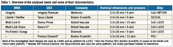
Stent strut apposition was evaluated by virtually implanting the stents in an idealised stenosed artery model, while the stent induced axial stresses were evaluated using a curved non-diseased vessel model (Figure 1). An inner diameter of 2.9 mm was used for the non-diseased vessel segments. The outer wall diameter was taken 1.6 times larger than the inner diameter as this results in a realistic wall thickness according to the anatomical data published by Holzapfel et al for non-atherosclerotic coronary arteries9. The layered structure of the arterial wall was taken into account and the ratios of adventitia, media and intima thickness to total wall thickness were 0.37, 0.36 and 0.27, based on the work of Holzapfel et al9. For the stenosed model, two asymmetric plaques were added, each characterised by a length of 3.9mm and a percent area stenosis of 61%. The curved sections of the tortuous vessel model have a radius of curvature of 12 mm. An anisotropic hyperelastic constitutive model was used to describe the mechanical behaviour of the three arterial layers9. This constitutive model was implemented as a user-defined material (VUMAT) in Abaqus/Explicit (Simulia, Providence, RI, USA) and the accuracy of the implementation has been demonstrated in a previous study7. Different material parameters were assigned to each arterial layer corresponding to Specimen I documented in reference 9. An isotropic and hyperelastic third order Ogden constitutive model was used to describe the mechanical behaviour of the plaque6. The vessel geometry and the corresponding hexahedral mesh were generated using pyFormex.
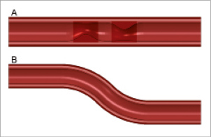
Figure 1. Cross-sectional view of the two vessel models. Stent strut apposition was evaluated using model A, while stent induced stresses were investigated in model B. The two asymmetric plaques are characterised by a percent area stenosis of 61%. The four different colours indicate the zones with different material properties (plaque, intima, media and adventitia).
Simulations
All stents were virtually deployed at 12 atm within the stenosed and the curved artery model as shown in Figure2 using the Abaqus/Explicit finite element solver. The stent strut apposition was evaluated for the stenosed vessel model after deflating the balloons by measuring the distance from the centreline of the outer stent surface to the inner surface of the arterial wall. For the Integrity stent, which has circular struts, the initial outermost point of the struts was taken for the distance measurements as indicated in Figure3.
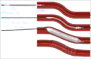
Figure 2. Illustration of the simulated insertion and deployment procedure. The top panel shows the original configuration. The position of the balloon-stent system prior to balloon inflation is depicted in the second panel. The third panel shows the deformations at the maximum balloon pressure, while the final configuration after balloon deflation is visualised in the bottom panel.
Figure 3. Measurement of strut-artery distance. Assessment of the stent strut apposition requires a quantification of the distance between the stent struts and the inner surface of the arterial wall. For stents with rectangular struts, the distance was measured between the arterial wall and the centreline of the outer (or abluminal) stent surface. In case of circular struts, the initial outermost point was taken for the distance measurement.
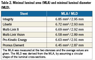
The minimal luminal area (MLA) at the two stenoses was measured after balloon deflation. This was done by importing the deformed luminal cross-sections into pyFormex, which contains functionalities to characterise two-dimensional closed curves. Corresponding minimal luminal diameters (MLD) were calculated by assuming a circular shape of the luminal cross-sections.
The stent induced vessel wall stresses were measured for the curved vessel model after balloon deflation. In particular, the 95 percentile of the axial stresses within the intima was calculated and compared. Only 5% of the volume of the intima has a stress value higher than this 95 percentile.
Results
Validation of the stent deployment behaviour
The accuracy of the compliance behaviour of the virtual balloon-stent systems was verified by comparing the simulation results with the data reported by the stent manufacturers. For all stents, the maximum percentage difference in diameter was less than 3% (for pressures up to 14 atm). A comparison of the virtual and a real deployment of the Integrity stent is depicted in Figure4. One can observe that the transient deployment behaviour (including the so-called “dog-boning effect”) is well predicted by the finite element simulation.
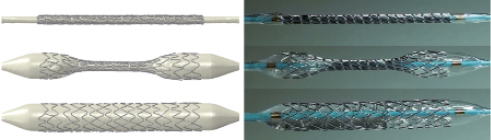
Figure 4. Validation of the virtual stent deployment behaviour. The virtual deployment of the Integrity stent is shown on the left, while a real deployment is depicted on the right. The deformations predicted by the finite element simulations correspond well with the experimentally observed deployment behaviour.
Stent strut apposition
All stents were virtually implanted in the stenosed artery model. Based on these deformed configurations, the distance between the struts and the inner arterial wall was calculated in order to quantify the stent strut apposition.
The contour plot shown in Figure5 illustrates the stent strut apposition of the different investigated stents. A blue colour corresponds with a minimal distance between the struts and the inner arterial wall and thus with a good apposition of the stent struts, whereas a red colour reflects a larger strut-artery distance. The struts of all stents are well apposed at the location of the stenoses. Severe malapposition, if present, occurs mainly immediately proximal or distal from the diseased segments.
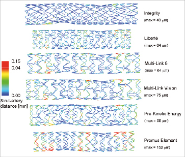
Figure 5. Contour plot of the strut apposition of the different stent designs. The contour plots show the distance between the centreline on the outer strut surface and the inner surface of the arterial wall. A nonlinear colour scale has been used, with red reflecting values between 0.04 and 0.15 mm, in order to obtain a better differentiation at lower values. The maximum strut-artery distance for every stent is also reported.
The percentage of struts at a distance larger than a certain threshold can easily be calculated by dividing the length of the centreline which is at a distance larger than this threshold by the total length of this centreline. This allows easy comparison of the different stents (see Figure 6). The percentage of struts at a distance larger than 0.01 mm ranges from 9% (Integrity stent) to 43% (Promus Element stent).
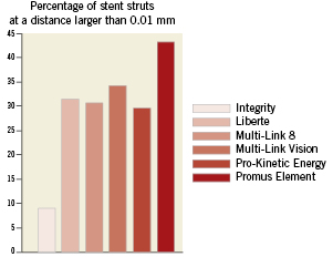
Figure 6. Comparison of the strut apposition of the different stent designs. The percentage of stent struts at a distance larger than 0.01mm is depicted in order to quantitatively compare the strut apposition of the different stents.
Luminal gain
The MLA was measured at the two stenoses and the average values are reported in Table2 together with the derived MLD. The two extreme MLA values are 6.45 and 6.85 mm², corresponding with the Promus Element and Integrity stent.
Stent-induced vessel wall stresses
The 95 percentile of the axial stress ranges from 32 (Promus Element stent) to 83 kPa (Liberté stent) as illustrated in Figure7. Acontour plot of the axial stresses at the intima-media interface is shown in Figure8. It can be observed that the highest tensile stresses are located at the inner curvatures and at the stent ends.
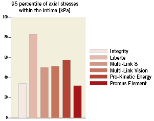
Figure 7. Comparison of the axial stresses caused by the different stent designs. The 95 percentile of the axial stresses within the intima was calculated in order to quantitatively compare the axial stresses caused by the different stent designs. Only 5% of the volume of the intima has a stress value higher than this 95 percentile.
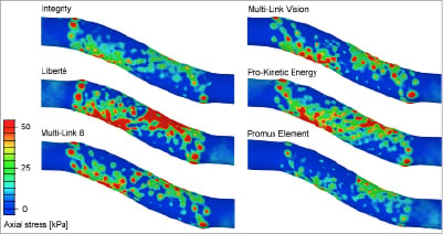
Figure 8. Comparison of the axial stress distribution after implantation of the different stents.These contour plots show the axial stresses at the interface between the intima and media. Stress peaks are mainly located at the stent ends and at the inner curvatures.
Discussion
Incomplete stent apposition (ISA) is the lack of contact between stent struts and the underlying arterial wall not overlapping a side branch. Several mechanisms may lead to ISA and a distinction should be made between acute and late malapposition. Acute malapposition occurs at the time of stent deployment and is more frequent with increasing lesion complexity (e.g., calcified lesions, larger vessels, longer lesions)10. At follow-up, initially malapposed struts can be well-apposed due to neointimal hyperplasia, or can remain malapposed (late persistent ISA). On the other hand, initially well-apposed struts may loose contact with the tissue because of positive remodelling of the vessel wall, or due to thrombus dissolution behind the struts (late acquired ISA)11.
Late ISA has been significantly associated with the development of OCT-detected thrombus at follow-up3. Ozaki et al hypothesised that the greater prevalence of attached thrombosis for incompletely apposed struts relative to well-apposed struts reflects the greater exposed surface area and the possible flow disturbances. However, the clinical relevance of incomplete stent apposition is still a matter of debate. Some studies suggest that incomplete stent apposition plays a role in the pathogenesis of stent thrombosis3,12,13, while other studies conclude that stent malapposition is a pure IVUS finding without significant impact on the incidence of major adverse cardiac events4,10,11,14-16. The main limitation of all these studies is their inadequate statistical power. It is extremely difficult to demonstrate an association between a relatively uncommon occurrence (late ISA) and an even rarer event such as very late stent thrombosis17.
In a recent study, Ozaki et al3 evaluated the mechanisms by which late ISA develops using both IVUS and OCT. They observed that 93% of the malapposed stent struts at follow-up were also initially incompletely apposed, suggesting that late persistent ISA is the predominant mechanism for late ISA. Therefore, the incidence of late ISA can be significantly reduced by optimising the acute apposition of the stent struts.
Our novel approach based on finite element simulations may help to better understand and to minimise acute ISA as it gives additional information compared to traditional evaluation methods (IVUS and OCT). The strut-artery distance can be quantified and visualised over the complete stent length, while currently used ISA measurements are typically based on IVUS and OCT cross-sectional images. In this way, the location of the malapposed struts can be identified and related to the artery and plaque morphology and the impact of different stent designs can be investigated. It should be feasible, however, to perform similar 3D analysis and visualisation of ISA over the complete stent length using 3D OCT reconstructions, although such analysis has not yet been reported. The proposed virtual ISA measurement procedure offers many other possibilities. It could be used to investigate and quantify the impact of different post-dilation strategies (e.g., balloon compliance, balloon pressure) and could provide additional insights for bifurcation stenting, where large strut malapposition frequently occurs.
The strut apposition of the different investigated stent designs differs considerably as illustrated in Figures5 and 6. The Liberté, Multi-Link 8, Multi-Link Vision and Pro-Kinetic Energy stent lead to a more or less comparable strut apposition, while the results suggest that the struts of the Integrity stent are generally closer to the vessel wall and that the Promus Element leads to a higher amount of malapposed struts in the tested model configuration. The large difference between the Promus Element and the Integrity stent is the result of many factors, such as differences in balloon compliance behaviour, stent design and material, strut cross sectional dimensions and shape. Interestingly, the Integrity and Promus Element stent correspond respectively with the largest (6.85 mm²) and the smallest (6.45mm²) luminal area. In other words, the Integrity stent results in a larger diameter as compared to the Promus Element stent when deploying both stents in the same stenosed vessel model (and at the same pressure of 12 atm). It seems reasonable to assume that a larger stent diameter leads to a better apposition of the stent struts.
The differences in MLA and MLD as reported in Table 2 are the result of the complex mechanical interaction between the balloon, stent and arterial wall. One important observation is that the deployment of the different balloon-stent systems at 12 atm in open air (i.e., without surrounding tissue) leads to different stent diameters, because of variations in balloon compliance, initial balloon diameter (at zero pressure) and resistance of the stent structure. The Promus Element stent results in the smallest stent diameter when expanded at 12 atm in open air and this partially explains why this stent leads to the smallest MLA. Logically, other aspects such as elastic recoil and radial strength (or stiffness) also affect the MLA.
The Integrity stent has struts with a circular cross-section, while all other included designs have rectangular struts. The measurement procedure used to quantify the strut-artery distance is slightly different for the circular and the rectangular struts and this may have an impact on the obtained apposition results. A strut with a rectangular cross-section might be partially in contact with the vessel wall but the applied measurement procedure might still indicate a gap between the strut and the vessel wall.
For all stents, the zones with the best strut apposition are the diseased segments, which can be explained by the higher stent-artery ratio at these locations. Consequently, increasing the stent diameter in the non-diseased segments may further improve the overall strut apposition. This finding confirms the importance of a tailored post-dilation to minimise ISA18. The largest strut-artery distances are observed at the plaque shoulders, suggesting that segments with strong variations in luminal diameter are more prone to ISA.
The stresses within the intimal layer were investigated as it has been suggested that these stresses in particular may act as a chronic stimulus for cell proliferation6. Low stresses induced by stenting are preferred in order to minimise the arterial injury and the resulting healing response. However, increasing the diameter of a stenosed vessel inherently leads to high circumferential stresses. Implanting stents in curved vessels also causes vessel straightening and leads to increased axial (or longitudinal) stresses within the vessel wall, which could be minimised by using more flexible stents. Our results clearly show that the currently available stent platforms have a distinct impact on the vessel wall and might therefore cause different levels of arterial injury.
All stents lead to stress peaks at the stent ends which may explain the frequent incidence of stent edge dissections19. These stress peaks may also contribute to the occurrence of restenosis immediately proximal or distal to the stented region. For example, Moses et al20 reported an in-stent restenosis rate of 3.2% when using sirolimus-eluting stents, but a restenosis rate of 8.9% was obtained by considering the stented vessel segment and the non-stented regions 5mm proximal and distal to the stent.
It should be noted that the axial stresses may also be influenced by the circumferential behaviour of the different stents. The stents have been combined with different balloon models in order to obtain realistic compliance behaviour for each balloon-stent system. In other words, deploying the stents at an identical pressure will lead to different stent diameters. This, in combination with variations in stent recoil and stent compliance, will result in different stent diameters after balloon deflation.
In this study, finite element analyses were used to assess stent strut apposition, stent-induced vessel wall stresses and MLA. These simulations can, however, also be used to assess other important mechanical stent characteristics such as flexibility, radial strength, eccentricity of the expanded state, etc. Those parameters have not been evaluated but may be of equal or greater importance.
Study limitations
All results should be interpreted carefully as they are based on numerical models which inherently contain a number of assumptions and approximations of which the most important are listed here:
–Residual stresses in the stents introduced by the crimping process are not taken into account.
–Virtual stent models were generated based on stent dimensions derived from micro-CT data. This process has been performed as accurately as possible, but it should be noted that the resulting stent models might slightly differ from the actual stent geometries (e.g., corner rounding of rectangular struts is neglected). In addition, only one sample of every stent was scanned and consequently, possible variations in strut dimensions between different samples were neglected.
–The material properties assigned to the stents are taken from reference 8 and might not fully reflect the real mechanical behaviour of the alloys (on stent level).
–The idealised vessel models do not reflect the in vivo encountered vessel and lesion irregularities.
The observed differences in strut apposition, lumen gain and axial stress state between the investigated stents are only based on one single case (one vessel geometry, one inflation pressure, one stent position, one set of material data for the arterial wall) and should therefore not be generalised to other cases. In future studies, every stent should be implanted in a range of more realistic patient-based vessel models and average output values should be reported. In addition, further in vitro and in vivo validation of the proposed modelling strategy seems advised. All these aspects will help to fully understand differences between stent platforms. Finally, it should be stressed that these tests may not be indicative of clinical performance.
Conclusion
The investigated stent designs demonstrate considerably different mechanical behaviour in terms of stent strut apposition (which was evaluated using a novel finite element based test), luminal gain and stent induced vessel wall stresses for the studied vessel models. The provided insights into the mechanical behaviour of the different stents may help to understand and to explain clinical observations.
Acknowledgement
The authors acknowledge Medtronic for providing the financial support for this study and for delivering all stent samples. They also acknowledge MPT Europe for the experimental data used to validate the virtual stent deployment behaviour.
Conflict of interest statement
Medtronic has provided financial support for this study and has delivered all stent samples.
Peter Mortier, Matthieu De Beule and Benedict Verhegghe are shareholders of FEops, an engineering consultancy spin-off from Ghent University, and have served as consultants for several medical device companies. The other authors have no conflict of interest to declare.