Abstract
Aims: Left main stenting is increasingly performed and often involves deployment of a single stent across vessels with marked disparity in diameters. Knowing stent expansion capacity is critical to ensure adequate strut apposition after post-dilatation of the stent has been performed. Coronary stents are usually manufactured in only two or three different model designs with each design having a different maximal expansion capacity. Information about the different workhorse designs and their maximal achievable diameter is not commonly provided by manufacturers but, in the absence of this critically important information, stents implanted in segments with major changes in vessel diameter have the potential to become grossly overstretched and to remain incompletely apposed.
Methods and results: We examined the differences in workhorse designs of six commercially available drug-eluting stents (DES): the PROMUS Element, Taxus Liberté, XIENCE Prime, Resolute Integrity, BioMatrix Flex and Cypher Select stents. Using micro-computed tomography, we tested oversizing capabilities above nominal pressures for the different workhorse designs of the six DES using 4.0, 5.0 and 6.0 mm post-dilatation balloons inflated to 14 atmospheres. MLD could be increased significantly in all stents, only restricted by workhorse design limitations. Minimal inner lumen diameter (MLD) achieved after two successive 6.0 mm post-dilatations of the largest design (4.0 mm stent) was 5.7 mm for the Element, 5.6 mm for the XIENCE Prime, 6.0 mm for the Taxus, 5.4 mm for the Resolute Integrity, 5.9 mm for the BioMatrix and 5.8 mm for the Cypher stent. Significant deformations were observed during stent oversizing with large changes in terms of cell opening and crowns expansion. These are affected by design structure and reveal important differences among all stents tested. Such extensive deformations may alter the functional ability of an individual stent to scaffold a lesion and prevent restenosis.
Conclusions: Stent selection based on stent model design may be critical, particularly for treatment of large artery and left main bifurcations where overexpansion is normally required to optimise results and ensure full expansion of the stent.
Introduction
Several recent trials suggest that PCI with a drug-eluting stent (DES) can be used in some patients with safety and efficacy similar to coronary bypass grafting (CABG) for the treatment of left main stenosis1-3. This procedure can require extensive post-dilatation to complete expansion of the stent, particularly for lesions localised across the bifurcation. Although DES are increasingly used for treatment of left main lesions, stent overexpansion capacity and performance remain mostly unknown at diameters above labelled use.
For bifurcation lesions, it is usually recommended to select a stent diameter close to the distal vessel segment diameter and then post-dilate the proximal segment of the stent to avoid compromising the SB with the carina shift phenomenon4. Previous in vitro bench micro-CT assessment of the impact of large partial post-dilatation has been performed for different overstretched DES by Basalus et al5. They showed the significant differences in strut deformation depending on axial location and platform tested. However, in this study, only a single diameter was tested and the influence of workhorse designs was not considered.
Stent workhorse design determines maximal expansion capacity and, in the absence of this critically important information, stents implanted in segments with major changes in vessel diameter may become grossly overstretched with potential incomplete stent apposition.
Methods
STENT DESIGN NOMENCLATURE
Stent model and workhorse design represents a particular stent “cut” which covers one or several diameters. Coronary stents are usually manufactured in only two or three different “model designs” with only the delivery balloon diameter changing to cover the entire range of available sizes (Figure 1).
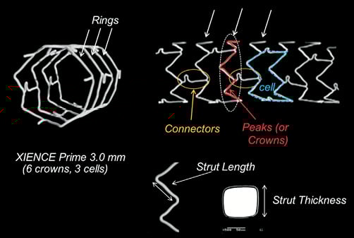
Figure 1. Stent design nomenclature. Number of crowns, strut and connector structure define each stent design and its mechanical characteristics. Rings provide radial support and expansion capacity whereas connectors hold rings together, contributing to the stent longitudinal structural stability. Example based on a XIENCE PRIME 3.0 mm (6 crowns, 3 cells).
Crowns or peaks (one peak/crown=two struts) are defined as the strut zigzag that forms the cross-sectional stent ring structure, providing stent radial support. Depending on the platform and workhorse design, stent rings are usually made of six to ten crowns.
Stent rings are connected together by connectors that maintain the longitudinal stability of the stent. A stent cell is defined as the area delimited by two layers of rings and the connectors, and the number of cells is therefore determined by the number of connector links between the rings.
The different designs were defined as small, medium or large vessel. By convention, we designated for each platform the workhorse design found at 3.0 mm as a medium vessel workhorse.
DES OVEREXPANSION EXPERIMENTS
We analysed the different workhorse designs of six commercially available drug-eluting stents (DES): the paclitaxel-eluting stainless steel TAXUS® Liberté® (Boston Scientific, Natick, MA, USA), everolimus-coated PtCr PROMUS Element™ (Boston Scientific, Natick, MA, USA) and CoCr XIENCE PRIME™ (Abbott Vascular, Santa Clara, CA, USA), the zotarolimus-eluting CoCr Resolute Integrity (Medtronic, Minneapolis, MN, USA), the biolimus-eluting stainless steel BioMatrix Flex™ (Biosensors International, Morges, Switzerland) and sirolimus-eluting stainless steel CYPHER SELECT® stent (Cordis, Johnson & Johnson, Warren, NJ, USA). We deployed samples of the different stent workhorse designs in vitro at nominal pressure (NP) and then tested the overexpansion capabilities of each design with successive post-dilatations using a 4.0×12 and a 5.0×12 non-compliant balloon (NC Quantum Apex; Boston Scientific, Natick, MA, USA) inflated at 14 atm; for the largest designs, we used a 6.0×15 mm semi-compliant balloon (Maverick XL; Boston Scientific, Natick, MA, USA) with a pressure of 14 atm. Post-dilatation was performed on the proximal segment of the stent, corresponding to a stent length of approximately 15 mm. Final dilatation was repeated twice to ensure an optimal expansion of the stent struts.
MICRO-CT ANALYSIS
The stent samples were mounted and analysed using micro-computed tomography (HMX 225; X-Tek, Tring, UK) with a resolution up to 15×15×15 microns. After reconstruction, sections of the stents were extracted for quantitative measurements and analysis of strut deformation. Proximal and distal sections of the stent were also compared to assess the difference in strut configuration between nominal diameter and after extensive overstretching of the stent (Figure 2).
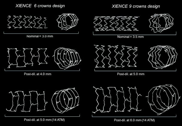
Figure 2. Strut deformation following post-dilatation of the two XIENCE PRIME stent models. Post-dilatation of the 6 crowns design medium vessel workhorse was performed with 4.0 and 5.0 mm balloons (left panel) and post-dilatation of the 9 crowns large vessel design was performed with 5.0 and 6.0 mm balloons (right panel). Straightening of the crowns can be observed when increasing post-dilatation balloon diameter until the stent approaches its absolute physical maximal expansion capacity.
MLD AND MSA
Cross-sectional minimal inner lumen diameter was defined as the minimal lumen diameter (MLD) measured on the cross-sectional reconstruction of the stent from the edge of the strut to the opposite strut edge. Depending on stent configuration after post-dilatation, inner lumen MLD was found either at the very proximal ring or further within the post-dilated segment. Minimal stent area (MSA) was defined as the cross-sectional inner lumen stent area excluding the stent struts and an estimated average inner lumen diameter was derived from the inner lumen MSA measurement.
CELL OPENING
Change in cell opening was estimated for each design after deployment at nominal pressure and at the maximal expansion diameter tested. From the side view of the stent cells obtained from micro-CT projection, cell opening was estimated using a circle with a perimeter fitted within the stent cell struts (Figure 3).
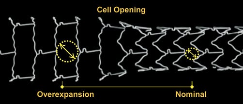
Figure 3. Comparison of cell opening at nominal diameter and after overexpansion. Post-dilatation of a 3.0 mm XIENCE stent with a 5.0 mm NC balloon. Cell opening was estimated using a circle fitted within the stent cell struts. For a stent ideally deployed in a vessel, the radius of the circle fitted within the cell represents the maximal distance of the arterial wall to a neighbouring stent strut.
For a stent ideally deployed in a vessel, the radius of the circle fitted within the cell represents the maximal distance between the arterial tissue and a neighbouring stent strut. An average of three measures was taken at nominal pressure (NP) and maximal dilatation for each stent design.
CROWNS ANGLE ANALYSIS
To assess the impact of post-dilatation on strut deformation, longitudinal sections of each stent were reconstructed from micro-CT by virtual slicing of specimens cut-open. From the longitudinal view of the stents (Figure 1), the angle between the two adjacent struts forming the crowns was measured using ImageJ (http://rsbweb.nih.gov/ij/,NIH). The strut angle was measured before and after post-dilatation on successive crowns (peaks and valleys, n=8), excluding crowns with a connector link.
Each measurement of inner MLD and MSA was repeated two times. Measurements were performed with an estimated approximation of ±0.05 mm. Results are provided as an average of the two measures with standard deviation. Comparisons between measurements were tested by analysis of the variance and t-tests. Intra-observer variability on MSA measurement was evaluated using Bland-Altman analysis. Each crown angle result is provided as an average of eight measures taken on different crowns and comparison between crown angles after post-dilatation was performed using the Mann-Whitney test.
Figure 4 summarises the different workhorses of each stent platform examined.
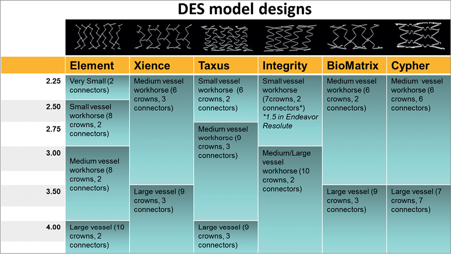
Figure 4. Changes in stent workhorse designs depending on diameter for 6 widely used drug-eluting stents. The figure indicates for each platform the different stent designs existing at the different nominal diameters, including number of crowns and connectors (number of cells=number of connectors).
Results
STENT WORKHORSE AND MODEL DESIGNS
Figure 5 indicates the cut-off diameter among different designs for the six DES studied. Four stent platforms were investigated: XIENCE Prime, Resolute Integrity, BioMatrix Flex and CYPHER SELECT stents have only two designs to cover the entire range of diameter. With the exception of the Resolute Integrity for which the designs change at 2.75 mm, the cut-off diameter for stents with two designs is generally at 3.0 mm with one workhorse design ranging from 2.25 mm to 3.0 mm and another large size workhorse design covering 3.5 mm and 4.0 mm diameters.
The TAXUS Liberté stent platform is provided with three designs: a small vessel design between 2.25 mm and 2.5 mm, a mid-size workhorse for diameters ranging from 2.75 mm to 3.5 mm and a large vessel design for 4.0 mm and above (DES are usually available to a maximal nominal size of 4.0 mm only with the exception of the TAXUS platform for which 4.5 mm and 5.0 mm sizes are also available).
The Element platform has the largest number of designs with four different designs: a very small vessel model for the 2.25 mm diameter, a small workhorse for 2.5 and 2.75 mm stent sizes, a mid-size workhorse for 3.0 mm and 3.5mm diameters and a large vessel design at 4.0 mm.
MAXIMAL EXPANSION CAPACITY
Measurements of the achieved stent inner lumen diameter are shown in Table 1, Table 2 and Figure 5. Most stents could be expanded well above their labelled maximal stent diameter with larger post-dilatation balloons. Achieved MLD (considering the minimal inner lumen obtained, excluding struts) after overexpansion was between 25% and 77% higher than the maximal nominal stent diameter, representing an average increase of 1.5 mm (ranging from 0.8 to 2.3 mm depending on the design).
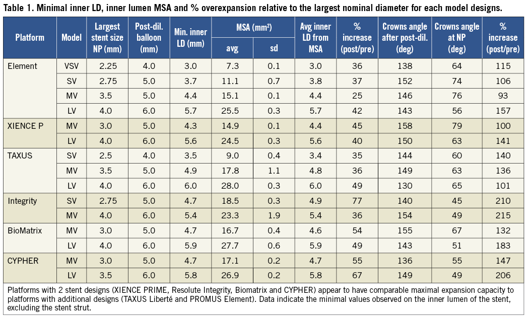
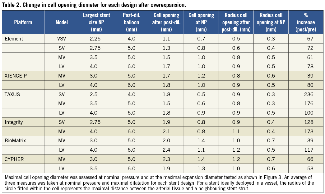
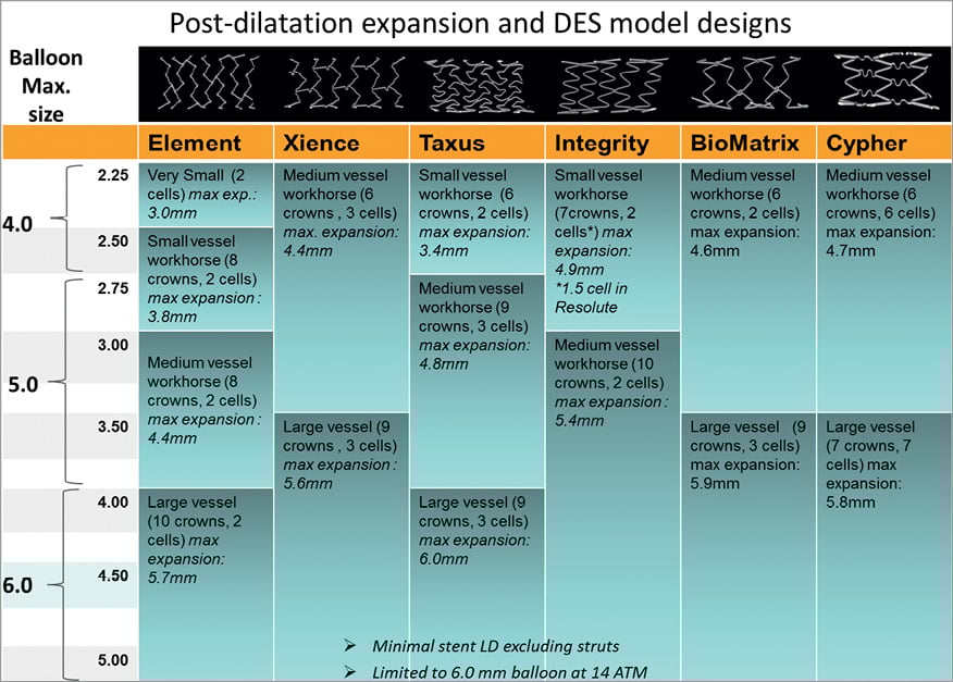
Figure 5. Expansion achieved for the different stent model designs of 6 widely used drug-eluting stents. Stent MLD derived from the inner lumen MSA measured following extreme stent post-dilatation with a balloon sized over 1.5 mm above the stent nominal diameter. Results showed that all stents have the capacity to be overexpanded well above their labelled maximal diameter. For most drug-eluting stents tested, MLD >5.5 mm was achieved after 6.0 mm balloon post-dilatation of the largest stent design. The figure also indicates the cut-off diameter between stent models, which is important in order to select a stent design which can be optimally expanded when a large change in diameter is present between the proximal and distal vessels.
Minimal inner lumen diameter (MLD) observed after overexpansion of the mid-vessel workhorse (3 mm size stent) was 4.3 mm for the XIENCE PRIME, 4.4 mm for the Element stent and equal or above 4.6 mm in all other stent designs. Minimal inner lumen diameter (MLD) achieved after 6.0 mm post-dilatations of the largest workhorse was 5.7 mm for the Element, 5.6 mm for the XIENCE PRIME, 6.0 mm for the TAXUS, 5.4 mm for the Resolute Integrity, 5.9 mm for the BioMatrix and 5.8 mm for the CYPHER stent. (We limited the study to a maximal balloon size of 6.0 mm).
On the largest stent design, minimal stent area (MSA) measured was the largest for the TAXUS and BioMatrix stents, respectively 28.0 mm2 and 27.7 mm2. Average inner LD derived from the inner lumen MSA showed very good agreement with the direct measures. Pearson correlation between repeated measures for the MSA was >0.996 and Bland-Altman analysis showed satisfactory reproducibility of measures with an average bias between measures of –0.16 and 95% C.I.=[–1.52–1.21].
CELL OPENING
Overexpanded stents were characterised by important strut distortion and large stent cell enlargement depending on the stent structure designs. As the average distance between adjacent struts increases, large gaps in strut scaffolding may lead to a risk of plaque prolapsing between struts and a reduction of the drug delivered per unit wall surface area (Figure 3).
Diameter cell opening was assessed for each design at the maximal expansion diameter tested and compared with deployment at nominal pressure (NP). Cell opening radius provides a quantitative indication of the maximal distance between the artery wall and the closest neighbouring stent strut.
For each given platform, cell opening was found to depend on workhorse design and expansion diameter (Figure 7 and Table 2).
Cell opening diameter measured on the stent at nominal pressure before overexpansion was on average 0.96 mm, with the smallest cell opening for the TAXUS designs (0.5, 0.6 and 0.9 mm), Integrity (0.8 and 0.8 mm) and PROMUS Element designs (0.7, 0.8, 1.0 and 1.0 mm) and the largest for the XIENCE (1.0 and 1.2 mm), BioMatrix (1.1 and 1.4 mm) and CYPHER designs (1.3 and 1.4 mm).
Cell opening radius increased on average by 99.1% with overexpansion over all the different stents evaluated: ranging from +59% and +60% on average for the two CYPHER and two XIENCE PRIME designs (p=0.01), to an average of +171% for the three TAXUS designs (p=0.003).
The largest cell opening diameters found after overexpansion were with the BioMatrix (2.0 and 2.4 mm), CYPHER (1.9 and 2.3 mm) and Integrity (1.9 and 2.1 mm) designs and the smallest in the Element four designs (1.1, 1.3, 1.5 and 1.7 mm).
CROWN DEFORMATIONS
With increasing post-dilatation diameter, the stent struts progressively straightened with some of the stent rings becoming almost circular in the post-dilated segment when approaching their stretching limit (Figure 2 and Figure 6).
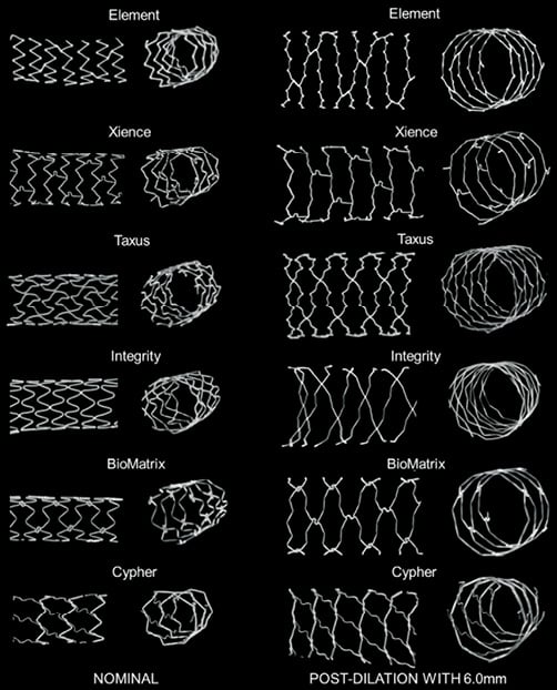
Figure 6. Strut deformation after post-dilatation with a 6.0 mm balloon. Stent longitudinal and cross-sectional segments of the largest workhorse design at nominal diameter (3.5 mm-4.0 mm) (left panel) and comparison with stent segment post-dilated using a 6.0 mm balloon (right panel). With extensive post-dilatation of the stent, stent expansion becomes limited by the straightening of the crowns. In the post-dilated segment, cell areas were widely enlarged compared to normal expansion. Some stent foreshortening, probably caused by protrusion of the pressurised balloon outside the stent was observed in some cases within the very proximal adjacent stent rings.
Post-dilatation caused a marked straightening of the stent crown angle from an average mean angle for all stents of 60.9±10.3º after nominal deployment to an average angle of 145.8±7.8º after the largest post-dilatation (p<0.0001). Average measured crown angle at nominal pressure after deployment ranged from 45º (Integrity 2.75 mm) to 79º (XIENCE 3.0 mm), compared to a range of 130º to 158º after maximal dilatation. Crowns on the XIENCE PRIME stent showed the greatest straightening with a respective average angle of 158±6º (MV) and 150±6º (LV) for each workhorse design (Figure 2 and Figure 3).
For the largest workhorses, after post-dilatation with a 6.0 mm SC balloon at 14 atm, the crowns appeared almost totally straightened on the XIENCE PRIME, Integrity, Element, BioMatrix and CYPHER platforms. Changes in strut angle after overexpansion were the largest with the CYPHER, BioMatrix and Integrity (respectively +206%, +183% and +215% for the largest workhorse design). By contrast, the stent crowns of the TAXUS largest design were not fully straightened with a 6.0 mm balloon and the average crown angle measured after overexpansion was only 130º, suggesting potential for further overexpansion on this particular platform.
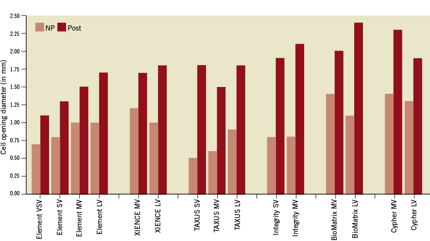
Figure 7. Diameter cell opening.
Discussion
In this study we compared DES platforms based on their workhorse design differences and used in vitro micro-CT analysis to assess the morphological stent changes after overexpansion of each stent design. Our main findings were that:
– Expansion capacity for each stent diameter is limited by its design. Therefore, if further post-dilatations with larger balloon sizes are intended, knowing the cut-off diameters between the different existing designs is critical for optimising stent selection.
– Most stents can be expanded well above their labelled diameter and recommended maximal diameter for post-expansion. On the largest design, inner lumen MLD >5.5 mm was achieved with most DES using a 6.0 SC balloon at 14 atm.
– Despite most stents achieving larger MLD, excessive overexpansion leaves large gaps between rings that may affect the ability of the stent to scaffold an atherosclerotic plaque lesion and the effectiveness of the antiproliferative drug coating to prevent restenosis.
RELEVANCE AND IMPLICATIONS OF THE STUDY
Several previous in vitro studies investigated stent oversizing and the impact of post-dilatation on DES using micro-CT techniques5-8. Basalus et al performed a comparison of the strut deformation following oversized proximal post-dilatation of four commercially available DES5. They found significant differences in final stent configuration and cell area depending on the location of the cell and among stent platforms. Overexpansion was, however, tested on only one stent diameter and limited to a 5.0 mm non-compliant balloon.
Stent deformation and polymer damage after kissing post-dilatation was also shown by Guerin on five different DES6. In both studies, only one stent diameter was tested and changes in stent designs at different diameters were not considered.
To our knowledge, the impact of stent model designs on overexpansion capacity has not been described in the past. Data on workhorse designs are not widely available and maximal expansion capacity is not usually provided by manufacturers. Stent design parameters such as maximal side branch opening for dilating side branch struts have been shown to be important in bifurcation techniques9,10. Both parameters are critically important when major changes in vessel diameter are present along the treated vessel segment, necessitating post-dilatation with larger diameter non-compliant balloons to ensure full expansion and apposition of the proximal section of the stent. Ongoing randomised trials, including the EXCEL trial (Evaluation of XIENCE PRIME versus Coronary Artery Bypass Surgery for Effectiveness of Left Main Revascularization), are exploring the applicability of second-generation DES for treatment of left main stenosis11. The considerations raised here are potentially of interest for stent post-dilatation in left main bifurcation anatomy where the difference in proximal to distal vessel diameters usually takes most platform designs over their labelled expansion capacity.
The recommended overexpansion is generally between 0.5 mm and 0.75 mm above the stent largest nominal diameter. Because of the large reference diameter in the left main stem and the large change in vessel diameter when compared with the left anterior descending and left circumflex arteries, a potential risk of reaching the maximal allowable radial expansion for a given stent can be inadvertently achieved. There are few common standards on testing overexpansion capacity. FDA guidelines on stent testing are focused mainly on flexibility and trackability testing12; no recommendations yet exist concerning the maximal expansion parameters of different stent designs. Extensive testing on structural changes, polymer integrity and drug efficacy are required to validate stent overexpansion as a label use. Despite being common in clinical practice, even outside of bifurcation territories, large post-dilatation is most often considered an “off-label” handling of stents, with limited data provided by manufacturers.
RISKS OF DES OVEREXPANSION
INCOMPLETE STENT APPOSITION
Incomplete stent expansion assessed with intravascular imaging is generally considered as a predicator of stent thrombosis and adverse outcome13,14; therefore, high-pressure post-dilatation of stents has generally been recommended to avoid incomplete stent apposition and to reduce the risk of stent thrombosis15.
Here we investigated whether stent maximal expansion capacity can be a limiting parameter for use of DES in the left main shaft and distal left main/ostial LAD lesions where PCI treatment is increasingly employed3.
Despite important structural deformation and crown straightening observed with all platforms, all designs tested could be overexpanded largely above their labelled maximal diameter, achieving MLD >5.4 mm with their largest design, sufficient to reach most left main diameters. Stents made with only two designs showed expansion capacity comparable to stent platforms made with three or four different designs. Interestingly, the “closed-cell” design did not seem to be a limiting factor in this in vitro study and the CYPHER stent showed large expansion capacity, above several other “open-cell” stent designs.
In summary, we propose that careful stent selection based on stent model design cut-off may limit the risk of incomplete stent expansion and the stent approaching its physical maximal expansion limit.
PLAQUE PROLAPSE AND IMPAIRED DRUG DELIVERY
Large cell enlargement observed after overexpansion may leave large gaps between strut scaffolding with a potential increase in the risk of the underlying plaque prolapsing between struts. Large overexpansion also affects drug distribution in the vessel wall, which may impact on the ability of the drug to prevent restenosis. A previous study by Guerin6 has also demonstrated a potential reduction of drug elution in the overexpanded segment following kissing balloon inflation. Whilst the impact of reducing stent scaffolding and drug distribution per unit surface area on restenosis has not yet been studied extensively, careful stent selection based on design cut-off diameters may limit such an effect.
DAMAGE TO DRUG COATING
First-generation DES generally present extensive polymer coating irregularities and damage even without post-dilatation16. Such coating damage has been correlated in vivo with a risk of delayed endothelisation and prolonged inflammation17,18. Second-generation DES, including XIENCE PRIME, Resolute Integrity, PROMUS Element, and Biomatrix Flex have shown better safety and clinical results than first-generation sirolimus and paclitaxel-eluting DES. Previous studies on first-generation DES showed a higher risk of polymer damage in struts overexpanded with the KB technique6. Extensive damage or dislocations of the polymer coating are likely to occur during overexpansion of the stent, all of which may increase the risk of delayed healing and stent thrombosis17-19.
STRAIN AND DISSECTION
In vivo animal studies have demonstrated how an overstretched stent can produce higher medial injury, increased inflammatory response and increased neointimal proliferation20,21.
In the clinical setting, changes in strut angle during overexpansion are likely to cause strain of the arterial tissue and potential dissections. The impact of crown straightening and strut overstretching on medial damage in clinical practice is also not known, and severe balloon overstretching may increase the risk of edge dissection or complete vessel rupture. This may be particularly significant with the KB technique which creates an elliptical deformation of the stent segment proximal to the SB with high strains in the wall and increased risk of stent damage and injury to the vessel6,7,22.
A stent recoil phenomenon is characterised by the reduction of the stent CSA compared to when inflated on its delivery balloon. By stepwise inflation of early BMS stent designs in a porcine model, Carrozza et al observed that stent recoil increased with larger expansion diameter and they showed that with an oversized balloon stent recoil could reach between 15% and 30% of the stent area23. In humans, Bermejo et al have also reported that, despite high-pressure inflation, lumen dimensions after stenting were only 57% of those theoretically expected24. Such observations have been confirmed by other IVUS and angiographic studies25-28 which suggest that stent recoil is an important real mechanism by which stents fail to achieve the same CSA as their dilating balloon. Therefore, some advocate overexpansion by 10% to 20% of the diameter relative to the reference vessel diameter to achieve an optimal stent result (final stent-to-artery ratio of 1.0)23.
As the struts straighten, the hoop force which a balloon has to overcome to compensate for the elastic stent recoil and to induce plastic deformation of the stent crowns becomes higher. It is likely that higher inflation pressure or a larger balloon diameter could produce a higher stent CSA than in our bench study.
Depending on stent configuration after post-dilatation, inner lumen MLD was found in the very proximal ring or further within the post-dilated segment. Although cell enlargement was observed where post-dilatation was applied, an important stent foreshortening of the adjacent very proximal stent rings could be observed for all stent designs if the oversized balloon was protruding, even minimally, outside the stent. Such risk of proximal stent foreshortening may be relevant in vivo where accurate positioning of the balloon under fluoroscopy is more challenging.
In summary, important limitations and concerns are raised when stents are severely overexpanded. Distortion of the stent crowns causes damage to the polymer coating6 and potential arterial laceration with the balloon protruding within the stent strut, all of which may be factors increasing the risk of adverse events, in particular stent thrombosis.
Furthermore, the mechanical response of overexpanded stents needs to be further validated. Overexpansion increases stent stiffness which may increase the risk of metal fatigue and the potential risk of fractures over time. As stent crowns straighten, the resulting radial force of the stent increases but overexpansion close to the maximal expansion capacity of the stent may result in an unpredictable mechanical response, particularly for helical stent design with only a limited number of connectors linking crowns together.
Study limitations
Results must be carefully interpreted as in vitro deployment without the arterial wall constraining the stent can only provide an approximation of the in vivo behaviour and stent-artery response during stent deployment. Results need to be confirmed in a larger number of experiments with stent recoil assessed. In particular, the hoop force which a balloon has to overcome to induce further plastic deformation of the stent crowns is expected to be significantly higher in vivo with stiff calcified plaque compressing the stent (Figure 8).
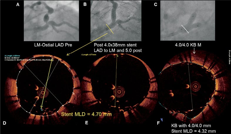
Figure 8. Illustration of a Resolute Integrity stent with incomplete stent apposition in a left main lesion. Severe left main stenosis (Medina 0,1,0) was noted on the coronary angiogram of a 62-year-old diabetic male admitted for exertional angina (A). After predilatation with a high-pressure balloon, a 4.0×38 mm Resolute Integrity stent (Medtronic, Minneapolis, MN, USA) was implanted across the bifurcation. After post-dilatation with a 5.0 mm balloon was performed (B), optical coherence tomography (OCT) revealed malapposed struts (D, E). Despite kissing inflation with two 4.0 mm balloons (C), OCT showed the inability to expand the stent further in the main stem (F).
We did not investigate the effect of overlapping balloons and kissing balloon technique in this study. Analysis of the impact of the KB technique in left main bifurcation may be the subject of further studies. Oval strut distortion may accentuate the risk of malapposition on the short axis of the stent.
Larger balloons and higher pressure may provide further straightening and stent expansion. Here we limited our experiment to a maximal balloon diameter of 6.0 mm, which is the largest available balloon size in most catheterisation laboratories and we also limited dilatation pressure to 14 atm (RBP) which may be considered relatively low compared to maximal post-dilatation pressure used in clinical practice.
Although most stents tested had a large capacity for overexpansion, as stent struts deform with extreme post-dilatations, potential large gaps impairing strut scaffolding can appear. Dilatation beyond stent labelled use should be avoided as mechanical efficiency and drug delivery efficiency of DES both remain unknown under such extreme overexpansion.
Conclusion
In summary, in an anatomy with large changes in diameters, inadvertent selection of a stent with only limited expansion capacity may lead to unpredictable results with grossly overstretched struts and a risk of incomplete strut apposition. Knowing cut-off diameters among the different stent model designs may lead to better stent selection and stenting results, particularly in the treatment of large bifurcation and left main PCI.
Acknowledgements
The authors would like to acknowledge the manufacturers who provided samples for this study.
Conflict of interest statement
Authors reported research support and clinical trial funding received from Medtronic, Abbott and Biosensors, unrelated to the present study.