Abstract
Bench testing of stents used in bifurcations can provide information on the general properties that influence performance including crossing profile, radial strength, recoil, flexibility and radiopacity. Problems with device delivery can be clarified. Bench testing identified that side branch dilatation caused stent distortion and elucidated correction strategies. Bench testing led to a stent design change adding connectors between hoops to help overcome the clinical problem of longitudinal distortion. Testing on the bench can determine best deployment strategies and showed that a two-step post-dilatation strategy produced the best deployment with “crush” stenting. Scanning electron microscopy showed that withdrawal of a coronary guidewire trapped between a stent (or scaffold) and a mock arterial wall during a provisional side branch stenting strategy caused only mild linear polymer coating damage. Stent fracture can cause adverse clinical events and our repetitive bend test identified the stents most resistant to fracture. Causes of obstruction of the passage of a balloon over a wire through the side of a stent include damage to the catheter tip, complex cell geometry and inadvertent passage of a wire behind a strut. Bench testing plays a major role in validation of computer modelling of bifurcation treatments and flow alterations.
Introduction
Bench testing of stents helps predict how they will perform in bifurcations. In its guidance for industry, the United States Federal Drug Administration stipulates that non-clinical (bench) testing should support the safety and effectiveness of intracoronary stents and their delivery systems ([email protected]). The International Organization for Standardization publication, ISO 25539-2, documents minimum requirements for endovascular devices and the methods of test that will enable their evaluation. Such testing helps determine the limits to which a device can be pushed, such as evaluating the device at extreme dimensions, and to assess performance at the outer limits of physiologic variables such as blood pressure, vascular compliance, and anatomic types1.
General properties of stents
Bench testing can provide information, well described elsewhere, on the important general properties of stents such as crossing profile, radioopacity, recoil, flexibility and radial strength2-4.
Stent delivery challenges
We studied dedicated bifurcation stent delivery in a phantom in a water bath with fluoroscopic recording because some two-wire dedicated bifurcation stents were clinically challenging to deliver5,6. We found that wire bias directed the SB component away from the SB, thus preventing device rotation and delivery (Online Figure1). We showed that a torquable shaft could actively rotate the bifurcation stent and allow easy delivery (Online Figure 1).
Stent deformation and side branch dilatation
More than 15 years ago we were surprised that dilatation through the side of a stent caused distortion7. Similar distortion also occurs in bioresorbable scaffolds8. There is a good and a bad side to this distortion and, if the balloon follows a wire that crosses to the SB through a distal cell near the carina, there is best clearance of struts from the SB ostium and best support of the proximal rim of the ostium by struts (Figure 1), as has been described again recently9. We and others have described an SB dilatation strategy preceded by proximal optimisation which assists distal crossing8,10.The bad side of distortion (narrowing of the scaffold distal to the SB ostium, malapposition opposite the ostium) can be corrected by a number of post-dilatation strategies (Online Figure 2). With conventional kissing balloon post-dilatation (KBPD), the proximal markers of both balloons are aligned (Online Figure 2). The site of maximum dilatation and symmetry of stent expansion with conventional KBPD varies greatly11 because of variability in how the balloons wrap around each other (Moving image 1). Distortion may be best corrected with mini-KBPD8, also called minimal overlap11, where only a short length of SB balloon lies in the MB (Online Figure 2). With “snuggle” balloons (Online Figure 2), the SB balloon lies entirely within the side branch12. MB post-dilatation up to the carina (final proximal optimisation treatment) is being studied as a possible distortion correcting strategy (Online Figure 2)13. In addition, sequential SB then MB dilatation has been studied as an alternative to conventional KBPD where proximal optimisation has not been employed13.
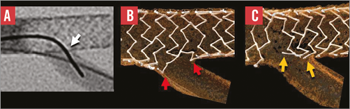
Figure 1. The importance of the site of crossing with wire and a balloon through the side of a stent to the side-branch. Crossing to the side-branch with a wire and balloon through a distal cell close to the carina (A) produces better clearance of struts from the ostium (B) compared with crossing through a proximal cell. Usually the operator has little control over the site of crossing.
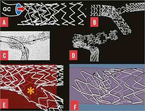
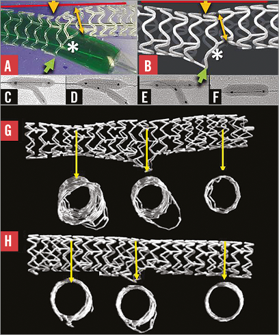
Figure 2. Bifurcation stenting and longitudinal stent deformation. A) A stent with two connectors between hoops was compressed by a guide catheter (GC) in a simulated left main coronary artery. B) A wire passed outside the main branch stent then re-entered the lumen. A balloon passing over that wire caused marked distortion on inflation. C) & D) This stent with two connectors between hoops was distorted by post-dilatation balloons. E) There was separation of stent struts (asterisk) with reduction in vessel support and antiproliferative drug application in this stent with only one connector between hoops. F) Compression of hoops, malapposition and obstruction were caused by a post-dilating balloon applying force to a proximal stent hoop.
Longitudinal stent distortion and bifurcation stenting
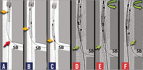
Following clinical reports of longitudinal stent distortion14-17 and our bench observations in bifurcations (Figure 2), we identified that stents with only one or two connectors between hoops were more easily distorted than those with more18. We proposed additional connectors between the proximal hoops of the Element™ stent design (Boston Scientific, Marlborough, MA, USA) where distortion was most common18. We subsequently showed that the Premier™ stent (Boston Scientific), which is the same as the Element but with additional connectors between proximal hoops, has a reduced potential for longitudinal distortion19. The mechanism of marked distortion of a stent that was not visible on angiography is shown step-by-step in Online Figure 3. A wire had passed from the lumen of a main branch stent to lie outside the stent for a short distance before it re-entered the lumen. Inflation of a balloon following this wire caused the distortions (Online Figure 3).
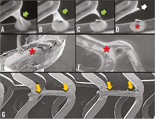
Figure 3. Drug-eluting stent coating imaged by scanning electron microscopy. A)-D) show a polymer web connecting adjacent struts of a first-generation drug-eluting stent (green arrow) breaking and leaving a bare area (asterisk) and redundant polymer (white arrow). E) & F) Areas of stent bare of polymer (asterisk) are shown after expansion of a different first-generation drug-eluting stent. G) Limited polymer coating damage (yellow arrows) to an Absorb scaffold caused by withdrawal of a Balance Middle Weight (Abbott Vascular) wire trapped between the deployed scaffold and the silicone mock coronary artery in a provisional SB stenting strategy.
Bench testing sheds light on deployment strategies in bifurcations
Online Figure 4 shows how balloon post-dilatation technique improves SB ostial metallic stenosis with the “crush” technique and how large gaps between stent struts can result when a balloon is inflated over a wire that has passed outside a stent and re-entered a lumen20. Bench testing can assist appropriate post-dilatation balloon size in, for instance, post-dilatation of stents deployed in the left main coronary artery21.
Drug-eluting stent polymer coating and scanning electron microscopy
Drug-eluting stent (DES) polymer coating integrity can be studied by environmental scanning electron microscopy (Figure 3). With one first-generation DES design, polymer webs between adjacent struts may break, leaving areas bare of polymer and redundant polymer coating (Figure 3). In a different first-generation DES, regions of damaged polymer appear related to the deploying balloon (Figure 3). While withdrawal of a 0.014”coronary guidewire trapped between a stent and a mock vessel wall during a provisional SB stenting strategy may damage the polymer coating, the damage is relatively small so unlikely to cause adverse events (Figure 3).
Stent fracture
Stent strut fracture which may occur with bifurcation stenting, especially with multiple stents, may lead to adverse clinical events22-24. We submitted six contemporary stent designs (n=15 of each design) to a repetitive bending test (Figure 4) and found that the BioMatrix Flex™ (Biosensors International, Singapore) stents all fractured between 10 and 100 thousand cycles, all the Vision® and Multi-Link 8™ (Abbott Vascular, Santa Clara, CA, USA) fractured between 100 thousand and 1 million cycles, and the Element and Premier (Boston Scientific) together with the Integrity design (Medtronic, Santa Rosa, CA, USA) did not fracture up to 10 million cycles (Figure 4)25.
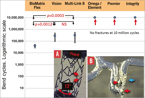
Figure 4. Mean and SD of number of bend cycles to fracture for the six stent designs (n=15 of each) tested. The BioMatrix Flex was the most readily fractured and the Omega/Element, Premier and Integrity did not fracture. Panel A summarises the testing method where one end of a stent was fixed and the other moved to flex the stent by 13º. Red arrows indicate the ends of a fractured strut. The red arrows in panel B indicate ends of a fracture and the blue arrow damaged polymer26. Modified from EuroIntervention, 2014 Nov 25 (Epub ahead of print), Ormiston et al26. Coronary stent durability and fracture: an independent bench comparison of six contemporary stent designs using a repetitive bench test. Copyright 2014 with permission from Europa Digital & Publishing.
Obstructed balloon passage to side branch
Bench testing shows causes of obstructed balloon passage from lumen to side branch.
Causes of obstruction include a balloon tip catching on the strut of a complex shaped cell, a coronary guidewire passing outside a strut and balloon catheter tip damage (Figure 5). Solutions to obstruction include re-wiring the SB hoping to cross through a different site in the stent, repeat post-dilatation up to the carina and using a new balloon.
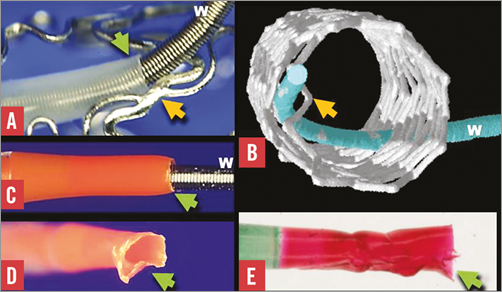
Figure 5. Some causes of obstruction of balloon passage to a side branch. A) A balloon tip (green arrow) passed over a guidewire (W), was obstructed by a stent strut (yellow arrow) in a stent where the cell shape was complex. B) The obstruction is due to a wire passing outside a strut (yellow arrow) before re-entering the main branch. C) A normal catheter tip (green arrow). Obstructed balloon passage may be due to a damaged catheter tip (green arrow in D and E) catching on a strut.
Improved bench testing phantoms
Our first phantoms were troughs cut in a perspex plate7. These secured the stent suboptimally during deployment and post-dilatation. Because there was no phantom material between the camera and stent, there was no light image distortion, and high-resolution images could be obtained. However, these phantoms were rigid, non-circumferential and very unlike a flexible, distendible tubular coronary artery1.
MicroCT allows phantoms to be made of a wide range of materials as they do not have to be transparent to allow conventional photography. For microCT imaging, initially we deployed stents in silicone block phantoms made by casting silicone over a metallic model of a bifurcation. Whilst these had radial flexibility compared with perspex, they did not have the longitudinal flexibility of a coronary artery. In addition, it was difficult to build anatomically accurate phantoms by casting.
We expect that bench testing information will improve with the use of more anatomically accurate phantoms. We used over 300 CT coronary angiograms to generate a statistical atlas of coronary anatomy with the aim of 3D printing anatomically correct phantoms. The relationship between the branch diameters follows Murray’s Law10,26. Materials used for 3D printing can have physical characteristics similar to those of coronary arteries and could be printed with stenoses.
Validation of computer modelling
We are comparing computer models of coronary flow with measurements of actual flow in an upsized physical model constructed according to Murray’s Law10 using magnetic resonance.
Conclusion
Bench testing has provided considerable insight into stent deployment and how different techniques might impact on clinical outcomes. Bench testing is essential to support the safety and effectiveness of coronary stents and their delivery systems. It can provide critical information on stenting techniques, how a device works, and whether there are likely to be concerns about device function, and it may predict clinical outcomes.
Funding
Auckland Heart Group Charitable Trust.
Conflict of interest statement
J. Ormiston is an advisory board member for Abbott Vascular and Boston Scientific and has received minor honoraria from them. O. Darremont is an advisory board member for Abbott Vascular. The other authors have no conflicts of interest to declare.
Online Figure 1. Bench testing sheds light on stent delivery problems. Wire bias in panels A-C directs the side branch component (yellow arrow) of a two-wire dedicated bifurcation stent away from the side branch (SB) preventing rotation and delivery. In panels D-F, a torquable shaft facilitates rotation and alignment with separation of wires (green arrows) making delivery possible.
Online Figure 2. Dilatation through the side of a stent and distortion correction strategies. Dilatation through the side of a stent or scaffold (A and B) causes deformation with malapposition opposite the side branch (yellow arrow), narrowing beyond the side branch ostium (yellow double-headed arrow), some protrusion of struts into the side branch (green arrow) and clearance of struts from the side branch ostium (asterisk). Strategies to correct distortion include conventional kissing post-dilatation (C) mini-kissing post-dilatation (D), “snuggle” (E), and main branch dilatation up to the carina (F)13. A stent after conventional KBPD (H) is compared with a stent after mini-KBPD (I).
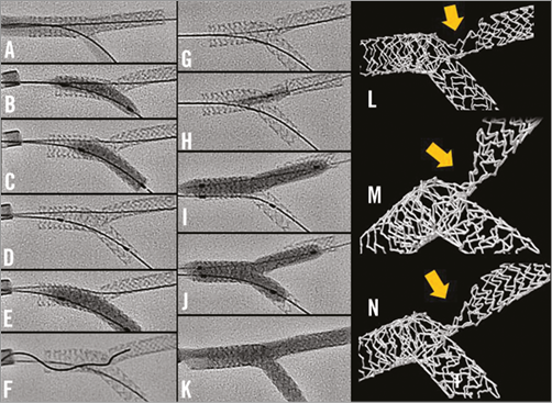
Online Figure 3. A mechanism of stent distortion with culotte deployment. A) A deployed 2.5×24 mm PROMUS Element stent (Boston Scientific) after proximal post-dilation with a 3.5×12 mm non-compliant balloon at 18 atm. The side of the main branch stent was dilated with a 2.5 mm balloon (B), then a 2.75 mm Vision stent was deployed from the main branch into the SB at 13 atm (C and D). This was post-dilated with a 3.0 mm balloon (E). The wire crossed with difficulty through the side of the SB stent (F) and was thought incorrectly to lie in the main branch stent beyond the SB origin (G). After a 3.0 mm semi-compliant balloon would not cross from the proximal to distal main branch, a 1.5 mm balloon did cross with difficulty being inflated (H). The main branch was post-dilated with a 3.0 mm balloon at 18 atm (I) before kissing post-dilatation with two 3.0 mm balloons at 6 atm (J). Angiographically, the result appeared good (K) but micro-CT imaging showed that the main branch stent was severely distorted (yellow arrow in L, M and N). It is likely that the wire exited from and then re-entered the main branch stent, and that the severe distortion was caused by inflation of the balloon passing over this wire.
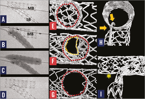
Online Figure 4. Bifurcation stenting with the “crush” technique, two-step kissing post-dilatation, and a complication. A stent deployed in the main branch (MB) has crushed part of the side branch stent in the main branch “crush technique” (A). High pressure (>22 atm) balloon inflation in the side branch (B) was followed by low-pressure kissing balloon post-dilatation (C) to correct distortion. E) - G) The side branch ostium viewed from the side branch. Struts “jailing” the side branch in (E) are partially cleared by conventional kissing post-dilatation (F) but are best cleared by high-pressure side branch (B) then kissing post-dilatation (C, G). H) A wire has passed from the lumen of the MB stent, through a gap outside the stents then re-entered the side branch stent. A balloon inflated after passing over such a wire can cause marked stent disruption with a large gap between distorted struts (I, asterisk).
Moving image 1. The site of maximum dilatation and symmetry of stent expansion with conventional KBPD varies greatly11 because of the variability in how the balloons wrap around each other.
Supplementary data
To read the full content of this article, please download the PDF.
The site of maximum dilatation and symmetry of stent expansion with conventional KBPD varies greatly11 because of the variability in how the balloons wrap around each other.