
Abstract
This is a consensus document from the European Bifurcation Club concerning bench testing in coronary artery bifurcations. It is intended to provide guidelines for bench assessment of stents and other strategies in coronary bifurcation treatment where the United States Food and Drug Administration (FDA) or International Organization for Standardization (ISO) guidelines are limited or absent. These recommendations provide guidelines rather than a step-by-step manual. We provide data on the anatomy of bifurcations and elastic response of coronary arteries to aid model construction. We discuss testing apparatus, bench testing endpoints and bifurcation nomenclature.
Abbreviations
ASTM: American Society for Testing Materials
CT: computed tomography
HK: Huo-Kassab
ISO: International Organization for Standardization
microCT: micro computed tomography
QCA: quantitative coronary angiography
3D: three-dimensional
US FDA: United States Food and Drug Administration
Introduction and objectives
A significant proportion of atherosclerotic plaques develop in coronary artery bifurcations, and percutaneous intervention in these regions carries higher risk of adverse events than elsewhere. In vitro bench testing can add to the anatomical and functional assessment of bifurcation lesions, guiding percutaneous therapeutic strategies. The US Food and Drug Administration (FDA) stipulates, in its extensive guidance for industry, that non-clinical (bench) testing should support the safety and effectiveness of intracoronary stents and their delivery systems ([email protected]). The International Organization for Standardization (ISO) publication, ISO 25539-2, details minimum requirements for endovascular devices and methods of test that will enable their evaluation. Test parameters for consideration include evaluating the device at extreme dimensions, in clinically relevant conditions and assessing performance at the outer limits of physiologic variables such as blood pressure, vascular compliance, and anatomic variations. Testing in a water bath or relevant fluid bath at 37±2°C is recommended by the ASTM F2079-09 for evaluating bioresorbable scaffolds. These organisations provide detailed guidance for general testing of stents (for instance for corrosion, stress/strain, fatigue analysis, particulate evaluation and more) but provide minimal guidance for bench testing of stents in coronary bifurcations.
This document, developed under the auspices of the European Bifurcation Club, is intended to assist bench assessment of stents and other strategies in coronary bifurcations where US FDA or ISO guidelines are limited or absent. It represents a starting foundation, and is expected to evolve over time. The recommendations, generated by clinicians, scientists and engineers, provide general principles, rather than a step-by-step manual. In this consensus, we propose consistent nomenclature and methodologies to standardise testing of bifurcation interventional procedures.
APPLICATIONS OF BENCH TESTING OF DEVICES IN CORONARY ARTERY BIFURCATIONS
In general, bench testing may evaluate different stents or scaffolds, different bifurcation treatment strategies, the local haemodynamic forces in bifurcations, validate quantitative coronary angiography (QCA) systems, and aid teaching of interventional techniques.
In the evaluation of QCA systems, precision-manufactured rigid Plexiglass models with bifurcation lesions have been contrast filled and imaged radiographically in different obliquities. The angiographic analysis can be compared with known diameters, lengths and angles of the model for assessing accuracy, precision, and reproducibility1.
Given the strong connection between biological responses such as restenosis and thrombosis, and perturbations in wall shear stress, it is useful to compute shear stress. Since computational models are based on assumptions, it is important to measure the velocity field and hence the associated shear stress in the region of the bifurcation to validate the computational predictions. Particle image velocimetry is one powerful method that allows visualisation of flow velocities in complex flow fields, with excellent temporal and spatial resolution2. Other methods to validate numerical simulations include measurement of flow in up-scaled bifurcation models using magnetic resonance imaging3.
Ideally, testing should be performed by an independent party to avoid selective testing, data interpretation or reporting4.
ANATOMY OF BIFURCATION MODELS
The geometry and material characteristics of models used should be reported. Early in the history of bench testing, very useful information was derived by testing in models that had limited anatomical accuracy and lacked the elastic response of human coronary arteries5. However, future bifurcation models are likely to be more anatomically correct, obeying geometric scaling laws and be constructed from materials that have an appropriate elastic response to improve the clinical relevance of testing.
SCALING LAWS OF FLOW
There are geometric rules known as scaling laws associated with the geometry of a coronary bifurcation. Nearly a century ago, Murray formulated the flow-diameter relation between proximal vessel and the branches6. Based on this scaling law and the conservation of mass through a bifurcation, a cube relation was found between the diameter of the proximal vessel and the sum of the diameters of branches (Figure 1). Although the power law relation holds, Murray’s exponent of 3 has been disputed for coronary arteries with the Huo-Kassab (HK) model7, showing a 7/3 exponent to be more precise (Figure 1). The Finet model8 is simpler and based on fractal arguments. It holds for Y-type but not T-type bifurcations (Figure 1), and also does not hold where there is a large discrepancy between branch diameters9. The Murray and HK models provide the flow distribution through the bifurcation in addition to the diameter constraints (Figure 1).
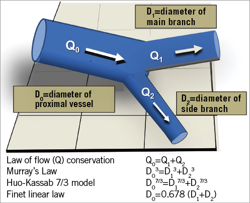
Figure 1. Conservation of mass and the geometric relationship between vessel diameters in a bifurcation. In accordance with the law of conservation of mass, the sum of the flows in the two branches equals the flow in the proximal vessel6-8. The relationship of the diameters of the bifurcation vessels from three different authors is shown.
DIAMETERS OF CORONARY ARTERIES AT DIFFERENT BIFURCATIONS, USING DIFFERENT MEASUREMENT MODALITIES IN DIFFERENT PATIENT SUBSETS
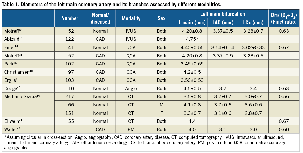
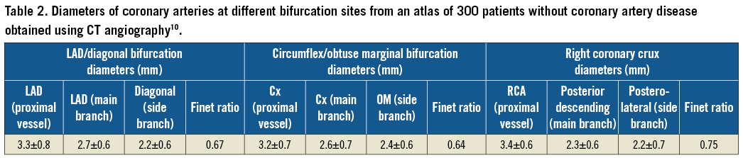
The vessels in bifurcations have different diameters in different individuals, at different sites and in different patient subsets (Table 1). The mean diameter of the left main coronary artery from different studies ranged from 3.5 mm10 to 4.75 mm11 (Table 1). Some of this variation is likely to be due to the differences in imaging technique with IVUS having higher resolution than invasive coronary angiography or CT angiography. Coronary artery diameters in bifurcations are larger in males than females10. There are likely to be differences in diameter between ethnic groups and at different ages10. The diameters of coronary arteries at different bifurcation sites, derived from an atlas of 300 patients without coronary artery disease, obtained from CT angiography, are shown in Table 2.
Coronary arteries taper. In a CT atlas, the tapering was 0.25 mm per 10 mm arterial length10 and in an intravascular ultrasound study it was 0.22 mm per 10 mm of artery12. The tapering was less in the right coronary artery than in the left anterior descending or circumflex coronary arteries12. Tapering is not gradually progressive, but occurs abruptly after each vessel branch.
NOMENCLATURE FOR ANGLES BETWEEN CORONARY BIFURCATION BRANCHES
In a bifurcation, the angle between the proximal vessel and the side branch is called angle A (Figure 2), that between the main branch and the side branch is angle B, and that between the proximal vessel and the main branch is angle C13-16. Since bifurcations are 3D structures, there is also an inflow angle between the proximal vessel and the plane of the branches (Figure 2)10,16.
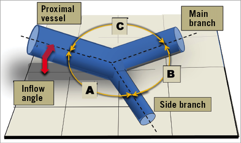
Figure 2. Nomenclature for the angles between bifurcation branches. Angle A is that between the proximal vessel and the side branch. Angle B is between the main branch and the side branch. Angle C is between the proximal vessel and the main branch. The inflow angle is between the proximal vessel and the plane of the branches.
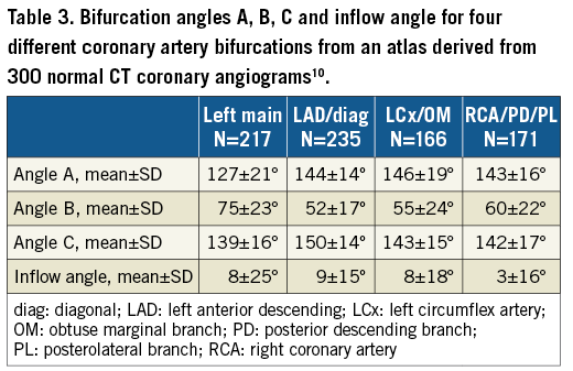
The numerical values for angles A, B, C and the inflow angle for four different bifurcations (left main, left anterior descending/diagonal, circumflex/obtuse marginal branch, and the crux) are shown in Table 3. The inflow angle is the smallest. Angle B is less than angle A or angle C. Angle B for the left main coronary artery is larger than that for the left anterior descending/diagonal or the left circumflex/obtuse marginal branch bifurcations.
While the angles A, B and C add up to 360º in a 2D plane, this is not necessarily true in 3D10. The inflow angle is greater in women than men probably because their hearts are smaller and more spherical, causing the coronary arteries to curve towards the apex10.
Measurements of the bifurcation angle B for the left main coronary artery, undertaken using different technologies and in different patient subgroups, are shown in Table 3.
The B angle in degrees for four different bifurcations is shown in Table 4. The nomenclature B’ is sometimes used to describe the angle between a straight projection of the main vessel centre line and the side branch, as shown in Figure 3 10,17-19. Angle B’ is always less than angle B.
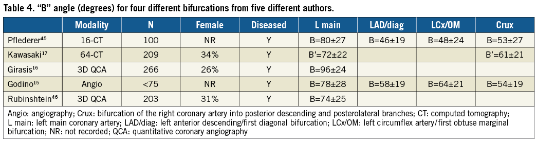
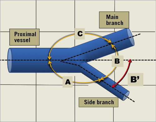
Figure 3. Derivation of the sometimes used nomenclature, angle B’.
CURVATURE
Blood vessels are seldom straight conduits, with curves and tortuosity being common. Because the heart can be considered to approximate a sphere, the coronary arteries must curve to follow the surface of that sphere10. In addition, arteries elongate and become tortuous with age20. Atheromatous plaque develops at bifurcations and curves where complex flow occurs21. In addition, the curvature of coronary arteries changes during the cardiac cycle, being greatest in systole. Stents cause straightening of the natural curvature of coronary arteries and can influence regional blood flow and alter distributions of indices of wall shear stress. Hence, specific areas, especially at the inlet and outlet of the stent, become more susceptible to neointimal hyperplasia. A limitation of most computational studies examining blood flow patterns through stented vessels to date is the use of linear, static, cylindrical geometric models22. Statistical shape analysis is addressed in the Supplementary Appendix and Supplementary Figure 1.
LEFT MAIN CORONARY ARTERY LENGTH
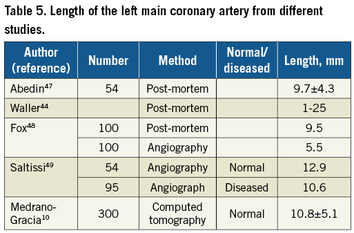
An atlas derived from 300 normal CT coronary angiograms found the length of the left main coronary artery from ostium to bifurcation to be 10.8±5.1 mm10. This generally agrees with the length of the left main coronary artery from other studies, as shown in Table 5.
PRACTICAL ANATOMY FOR CORONARY BIFURCATION MODEL CONSTRUCTION
While we have presented detailed bifurcation angle data, it may be practical to construct phantoms with B angles of 30, 60 and 90º and a C angle of, for instance, 140º. The diameters for different bifurcation sites could be chosen from our summarised data (Table 1) and could obey fractal geometry guidelines. Models could be constructed with an inflow angle to represent anatomy accurately.
THE CARINA
There are challenges in the manufacturing of bifurcation models with an anatomically correct carina. Attempts usually result in a carina that is too thick and rigid. An anatomically correct carina would aid insights into the efficacy of post-dilatation techniques in bifurcations.
CORONARY STENOSES AND BIFURCATION MODELS
Models can be constructed with stenoses although there are limited published data on this23. To validate quantitative angiography, rigid mock vessels with stenoses have been precision drilled in Perspex1,24. It is likely that models with stenoses will become more widely used so that devices and strategies can be tested in more realistic situations. In addition, individual patient-specific models can be 3D printed to test strategies before clinical treatment.
NORMAL CORONARY ARTERY ELASTIC RESPONSE
Knowledge of the elastic response of normal and diseased human coronary arteries is important to facilitate construction of realistic bench testing models. The elastic response of a coronary vessel can be expressed in terms of compliance, distensibility, stiffness or elastic modulus, as defined in the Supplementary Table 1.
MODELS AND MODEL CONSTRUCTION MATERIALS
In addition to appropriate design, elastic properties and construction material, the model should permit imaging of deployed stents. Historically, the different phantom materials and designs that have been used have limitations.
Troughs in Perspex plates lack anatomical bifurcation accuracy (Figure 4), lack an elastic response and are non-tubular5. These phantoms are good for light photography because there is no material between the stent and the camera.
Glass tubes have been used for bifurcation models but have limitations including difficulty manufacturing with anatomical accuracy, high wall rigidity and distortion of light images.
Tubing from aliphatic polyether-based thermoplastic polyurethanes (Tecoflex) has been used when measuring radial strength and assessing longitudinal distortion25. This tubing is difficult to make into anatomically correct bifurcations. Photography is difficult because of limited translucency, but the tubing is suitable for micro computed tomography (microCT) imaging.
Casts made from silicone can be anatomically accurate but need to be modified to allow quality light photography (Figure 4). They can be tubular and can have a suitable elasticity. They are suitable for microCT imaging.
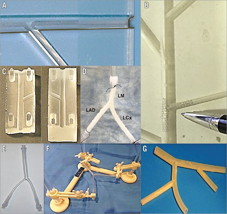
Figure 4. Some bifurcation models. Our first model (A), constructed in the 1990s, had troughs cut in a poly (methyl methacrylate) acrylic plate (trade names include Perspex)5. This was hard and rigid, not tubular and did not obey scaling laws but permitted unrestricted conventional photography. B) A model made from silicone by the Massy group about 20 years ago and used in early experiments with side branch dilatation50. C) A model cast from silicone where two halves can be separated to allow conventional photography. The model in panel D is a 3D printed left main coronary artery based on realistic geometry and using polyurethane with hyaluronic acid as sacrifice materials. The bifurcation is mounted on a bioreactor perfusion system. The image in panel E from Finet is constructed from polyvinylchloride (PVC) according to scaling geometry and is fixed in a nylon support to maintain angles between branches (F). The model in panel G was made by 3D printing (also called additive manufacturing) which has the potential for construction of realistic phantoms with normal or diseased anatomy and the potential to be made from a material with an appropriate elastic response.
With 3D printing, realistic models with normal or diseased anatomy and made from a material with an appropriate elastic response can be constructed.
3D bioprinting and tissue engineering can also be used to fabricate in vitro coronary arteries with human-like anatomy, precise wall architecture based on extracellular matrix, multiple cell types including endothelial and smooth muscle cells, and more physiologically and biomechanically relevant microenvironments26. These arteries can be tested in bioreactor perfusion systems.
Accurate dimensional and angle data are needed for accurate model construction. Another approach to model construction is first to to print a mould which can be used to cast silicone or other material. There is a wide variety of materials that can be used for 3D printing including plastics, metals, ceramics and even paper.
IMAGING OF STENTS OR SCAFFOLDS IN CORONARY BIFURCATION MODELS
The deployment of stents, scaffolds or other devices in models in a water bath and subsequent steps including proximal optimisation14, side branch wire access, and additional stenting can be viewed live and recorded fluoroscopically, on video or with serial photography. The device can be removed from the water bath temporarily or permanently so that a particular step can be imaged by, for instance, photography or microCT.
Photography through a microscope is very useful to record images of devices during a wide range of manoeuvres. Multiple images can be acquired easily and in a cost-effective way. Stent deployments have been imaged through a borescope (paediatric endoscope)27, but this technique has been largely superseded by microCT.
While microCT is limited by cost and time requirements, it does allow unparalleled imaging28,29. The images can be readily post-processed with computer algorithms allowing slicing and advanced viewing such as “fly-through”. A limitation is that image reconstruction often uses gaming software that distorts the images and precludes accurate length measurement. There may also be problems with contrast resolution between the bench model polymer and the stent or scaffold being tested.
Intravascular ultrasound and optical coherence tomography are useful imaging tools for stents and scaffolds, providing high resolution, and reconstructions to produce 3D patient-specific images30.
The very high resolution of scanning electron microscopy is useful for examining polymer coatings on stents (Figure 5).
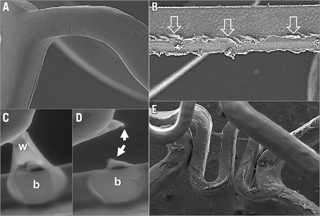
Figure 5. Polymer coating appearances on scanning electron microscopy. A) The smooth appearance of an undamaged drug-eluting stent polymer coating. The linear polymer coating damage (open arrows) in panel B was caused by withdrawal of an 0.014” percutaneous intervention wire that had been intentionally trapped between the expanded scaffold and model arterial wall. C) A first-generation drug-eluting stent with a polymer web (w) connecting two struts which in panel D had broken, leaving an area of strut bare of polymer coating (b) and some redundant polymer (white arrows). E) Marked irregularity of coating on the luminal surface of a different first-generation drug-eluting stent immediately after deployment.
UNIVERSAL TESTING MACHINES
When testing stents on the bench, it may be necessary to apply a measured force (often very small) and measure the distance compressed or elongated (which is usually very small) or conversely elongate or compress a stent or balloon tip by a chosen distance and measure the force required to do this. This may be achieved by using a universal testing machine such as an Instron (Norwood, MA, USA). These machines are basic instruments found in engineering and bench testing facilities.
SPECIMENS TESTED
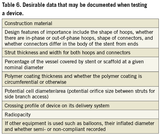
A report of stent or scaffold testing in bifurcation models would usually document or reference the properties of those devices being tested. Nominal diameters are important to record as different diameters from the same manufacturer may have different designs. Stent lengths and the number of specimens tested should be documented. Stent structural data are important for understanding stent performance in bifurcations. Some of these data may be obtained from the manufacturer or deduced from images. Desirable data that might be included are shown in Table 6.
TESTING APPARATUS AND TESTING PROCEDURE
In a bench testing report, any testing apparatus should be described in detail and images and/or diagrams provided. It is often necessary to custom-make apparatus to answer specific questions25,31,32. Any post-dilatation strategy should be described in detail.
BENCH BIFURCATION TESTING ENDPOINTS
An unanswered clinical bifurcation question may lead to testing of devices on the bench. The question should be clinically relevant, and testing endpoints should be determined by the question. For instance, if the question is scaffold post-dilatation safety without strut fracture then the scaffold would need to be observed for fracture after pressure or diameter post-dilatation challenge.
Stent or scaffold performance characteristics that are important but not specific for bifurcations include recoil, radial strength, flexibility, fracture resistance, longitudinal strength and security from dislodgement off the delivery balloon. Testing for these properties is covered by the US FDA recommendations ([email protected]), and the ISO publication, ISO 25539-2.
Many bifurcation bench studies aim to provide insights into bifurcation stenting or scaffolding by evaluating results obtained for particular platforms or strategies. Endpoints for bench studies in bifurcations might include the following parameters. Whenever possible, quantitative measurements should be reported.
DEVICE DELIVERABILITY
Different tracks or models with different degrees of tortuosity or stenosis can be used to compare the performance of different devices (ASTM F2394-07). Observation of bench delivery has identified wire bias and wire wrap as causes of delivery problems for dedicated bifurcation stents that deliver over two wires4. Bench testing showed that a steerable shaft on a dedicated bifurcation stent permitted device rotation facilitating wire unwrapping and the overcoming of wire bias33.
DEPLOYMENT QUALITY
Presence or absence of stent or scaffold underexpansion, distortion, cross-sectional area, diameters, eccentricity, and malapposition can be assessed34,35. The percentage of the side branch ostium occupied by struts can be assessed.
STENT OR SCAFFOLD DAMAGE
Strut fracture or polymer coating damage can be determined25,36. Strut fractures can be counted under direct observation, microscopic observation or by microCT. Polymer coating damage (Figure 5) can be imaged with scanning electron microscopy. Ideally there should be quantification of damage37.
CORRECTION OF DISTORTION
Effectiveness of strategies such as kissing balloon post-dilatation for distortion correction can be assessed2.
SIDE BRANCH ACCESS
Performance and integrity of different stents or scaffolds or balloons when crossing through the side of devices into the side branch can be evaluated. Cross-sectional stent area and lumen diameter at selected reference landmark locations in the proximal and distal main vessel, bifurcation, and side branch segments can be measured38.
Percentage of ostial area stenosis can be calculated as follows: (reference segment side branch lumen area minus largest opened stent cell area)/reference side branch lumen area29.
Limitations of bench testing
Bench testing involves simplification of bifurcation anatomy, bifurcation lesions, or treatment techniques. Bench testing may not predict what occurs in patients. Coronary models do not currently reflect the complexity of human diseased arteries. Models are usually stationary and do not reflect the complex motion of bifurcations during the cardiac cycle39. Advanced tissue engineering and 3D bioprinting techniques26 capable of generating arterial systems with realistic anatomy and function are anticipated to advance the field of bench testing for coronary artery bifurcation treatment in the coming years.
Summary and conclusions
We have provided guidance for bench testing of stents or scaffolds in coronary bifurcations. It is intended to be a guide, and not be prescriptive, as this is an evolving field. These recommendations provide general principles that have been developed by clinicians, scientists, and engineers. The focus is on issues specific to intervention for bifurcation disease that are not covered by ASTM or ISO documents.
| Impact on daily practice We provide data on the anatomy of coronary artery bifurcations, and on the elastic response of coronary arteries to optimise model construction. We also give guidelines for standardised bench assessment of coronary stents, and of percutaneous coronary interventional techniques, including stent deployment, for treating coronary bifurcation lesions. Bench testing may aid clinical practice by elucidating the local haemodynamic forces in bifurcations, by validating quantitative coronary angiography systems, and by facilitating the teaching of interventional techniques. There is potential for 3D printing of bifurcation anatomy specific to a patient, so that different treatment strategies can be assessed, and treatment individualised for that patient. |
Conflict of interest statement
T. Mickley is an employee of Boston Scientific Corporation. H. Hojeibane is an employee of Stentys. J. Wooton is an employee of Medtronic Corporation. A. Netravali is an employee of Abbott Vascular. The other authors have no conflicts of interest to declare.
Supplementary data
Supplementary Appendix. Averaging coronary artery bifurcation shape (statistical shape analysis).
Supplementary Figure 1. Modes of variation.
Supplementary Table 1. Summary of published data on arterial volume compliance, distensibility, and Young’s modulus for canine and porcine models and in humans.
To read the full content of this article, please download the PDF.