Abstract
Aims: To validate patient-specific computational testing of a second-generation device for percutaneous pulmonary valve implantation (PPVI), against realistic in vitro data.
Methods and results: Tests were initially carried out in a simple loading mode, performing a compliance test on a rapid prototyped cylinder. This model was reproduced computationally and validated against the experimental data. A second-generation PPVI stent-graft, with no valve mounted, was then deployed in a simplified cylindrical geometry, measuring its displacement when subjected to a pressure pulse. Experimental and computational measurements were in good agreement. Finally, having selected a patient regarded as unsuitable for first-generation PPVI, but potentially suitable for a second-generation device, the stent-graft was studied in the rapidly prototyped patient-specific right ventricular outflow tract (RVOT). Stent positioning and radial displacements with pulsatile flow were observed in a mock circuit using fluoroscopy imaging. Stent deformation and anchoring were measured both in vitro and computationally. Both tests indicated that the stent was well anchored in the RVOT, especially in the distal position, and its central region was rounded, ensuring, were a valve present, optimal valve function.
Conclusion: We suggest that an experimentally validated computational model can be used for preclinical device characterisation and patient selection.
Introduction
Preclinical tests aim to provide a comprehensive analysis of device safety and utility. Animal in vivo testing has the advantage of evaluating biological responses and acquiring histological information. However, human anatomy and dynamics can be substantially different from animal models1. Bench experiments offer a controllable and reproducible environment in which a device can be tested systematically and its long-term performance assessed. However, the evaluation of biological responses is lacking, test beds are often greatly idealised, and accurate reproduction of loading conditions can be challenging. More recently, advances in computational technologies have rendered computational testing an appealing and cost-effective tool for investigating a device’s mechanical performance, and it has been proposed that “virtual bench testing2” could become the new standard for testing novel cardiovascular devices3 and for clinical training4. However, in order for virtually-generated results to be reliable, thorough validation against physical data is necessary5,6, and for them to become clinically useful as a teaching and practice tool, the inclusion of patient-specific features is mandatory. Suitably combined in vitro and computational methodologies may provide powerful tools to study new devices7, especially for transcatheter valve implantation, in which preprocedural assessment is fundamental for correct patient selection and successful procedural outcomes8. From our experience with the current percutaneous pulmonary valve implantation (PPVI) device (Melody™; Medtronic, Minneapolis, MN, USA9), clinical practice has shown different device performance compared to that obtained from bench and animal experiments during preclinical testing. For example, conventional in vitro testing for fatigue assessment did not predict stent fractures, which can occur in up to 20% of device implants10. This discrepancy is most likely due to the fact that realistic, in vivo loading conditions could not be correctly replicated in the experimental set-up11. More recently, a second-generation PPVI stent-graft (Medtronic) has been designed to fit dilated right ventricular outflow tract (RVOT) morphologies12, which have a high variety of shapes, sizes and dynamic motions. The aim of this study was to create both novel in silico (computational) and in vitro (bench) models that might be used to improve the preclinical testing of transcatheter valve devices. We have used advanced computational modelling to assess the device performance in a patient-specific case study and we have validated the computational model using experimental data. The combined methodology provides an insight into the device’s mechanical function from different perspectives, while the patient-specific approach assesses the patient’s suitability for second-generation PPVI.
Methods
The second-generation PPVI device has a symmetrical hourglass shape with the valve positioned in the central portion13. The stent-graft comprises six nitinol rings (numbered 1 to 6 from proximal to distal [Figure 1]) interwoven with polyester fabric (Figure 2B). Rings 1 and 6 are nested inside the adjacent rings (2 and 5, respectively) while all the other rings (2 to 5) are connected to each other with a point-to-point suture (Figure 2B). The valve was not taken into consideration in this work. The device was studied both in vitro and computationally, in a parallel manner, with increasing levels of model complexity (Figure 2). For all the following tests, the bench model was first used to define the experiment and measure a specific outcome. The computer model was then created to mimic the in vitro set-up, so that the virtual calculated result and the real measured outcome could be directly compared in an attempt to validate the computational model.
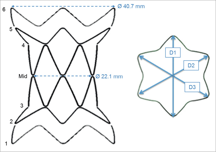
Figure 1. The stent-graft can be divided into six sections (1-6), symmetrical with respect to the centre of the device (mid). Three main diameters (D1, D2 and D3) can be identified for each section.
Data were analysed using Pearson’s correlation and Bland-Altman plots, and p<0.05 was considered to denote statistical significance. Statistical analysis was performed using SPSS for Windows, version 19 (SPSS, Chicago, IL, USA).
Boundary object material and computational model validation
A compliant cylinder (23 mm internal diameter, 72 mm length, 1.5 mm thickness, Figure 2A) was rapidly prototyped by the PolyJet™ technique using the commercially available TangoPlus FullCure® 930 compound (Objet Ltd, Rehovot, Israel)14,15. A compliance test was carried out on the cylinder by closing the ends with fitting lids, thus creating a closed volume filled with water (V0 =29.9 ml), and by varying the volume (ΔV=10 ml) incrementally in steps of dV=1 ml, using a syringe inserted from one end of the cylinder. Simultaneously, pressure was continuously recorded inside the cylinder using a high-fidelity, factory pre-calibrated, fibre-optic pressure catheter (Preclin 420; Samba Sensors, Västra Frölunda, Sweden). The pressure-volume relationship (Figure 3) was analysed to deduce information on the material properties. Compliance was estimated from the slope of the curve, yielding C=0.1 ml/mmHg for the imposed ΔV=10 ml. Given the cylinder’s volume V0=29.9 ml, distensibility was calculated as D=C/V0=0.36×10–21/mmHg. The value of the experimental Young’s modulus was
![]()
where P=internal pressure, R=radius, k=wall thickness and Δcirc=variation in the circumference.
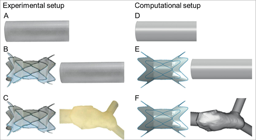
Figure 2. Tests were carried out experimentally (left) and computationally (right) in models of increasing complexity: a simple loading mode applied to a cylinder and not considering the stent-graft (A and D); deployment of the stent-graft in a simplified geometry (B and E); and deployment of the stent-graft in a patient-specific geometry (C and F).
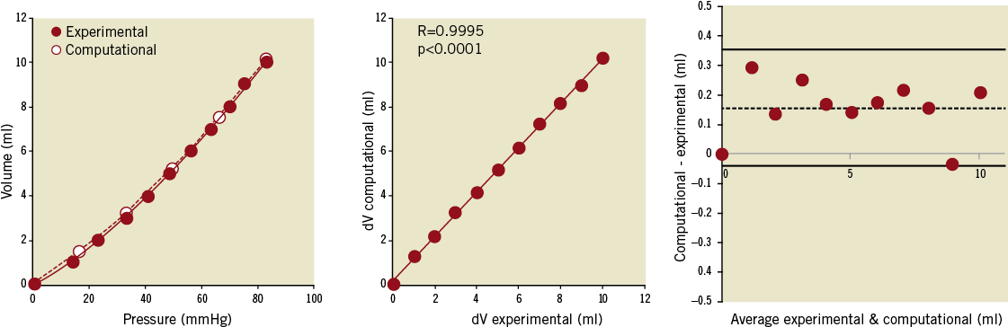
Figure 3. Experimental and computational compliance loading curves obtained from pressure and volume couples in the cylinder (left). The correlation between experimental and computationally-derived variations in volume (dV) is shown (centre) together with the Bland-Altman plot with a small positive bias towards the computational results (right).
The same cylinder was reconstructed for finite element (FE) analysis (Abaqus; Dassault Systèmes, Simulia Corp., RI, USA), meshed with 16,024 solid hexahedral elements with reduced integration (Figure 2D), and fully constrained at both ends. The material was assumed to be homogeneous, isotropic and linear-elastic, with E set according to the experimental value, and an assumed Poisson’s ratio of 0.2516. The measured density of the material was 1,190 kg/m3. For the computational model, a variation in the internal pressure ΔP corresponding to the values measured experimentally was imposed to the internal surface of the cylinder and the corresponding ΔV was calculated.
Stent-graft computational model validation in a simplified, symmetrical geometry
As a second stage of the testing process, the stent-graft was released into the cylinder described above and subjected to pulsatile flow, both experimentally (Figure 2B) and computationally (Figure 2E).
In vitro, a simple mock circulatory system was assembled. The ventricle was simulated with a left-ventricular assist device (EXCOR®60 cc; Berlin Heart, Berlin, Germany) fitted with tilting disc valves, driven by a PC-controlled piston17,18. Stroke volume (SV) was set at 40 ml and heart rate (HR) at 50 bpm. The stent-graft was released into the compliant cylinder, which was attached to the outlet of the ventricle. Pulmonary vascular resistance (PVR=3.9 WU19-21) was implemented using a needle-pinch valve previously characterised, and pulmonary compliance using a Windkessel chamber with adjustable air volume, set at 1.65 ml/mmHg. An atrial reservoir provided constant head pressure. The circuit was filled with a solution of 33.5% glycerine in water by weight at room temperature as a blood analogue22. Pressure was measured inside the cylinder using a fibre-optic pressure sensor (Preclin 420), indicating a pressure pulse of 100 mmHg. The stent-graft movement inside the cylinder during pulsatile flow was visualised and recorded at 50 frames/sec (Powershot G11; Canon, Tokyo, Japan). The images were post processed frame by frame to measure the expanded diameter of the stent-graft over the cardiac cycle.
Computationally, the stent-graft geometry was reproduced in computer-aided design (CAD) software and exported to the FE software. The nitinol stent rings were meshed with 900 beam elements and the polyester fabric with 5,094 shell elements following sensitivity analysis. The material properties implemented in the analysis were provided by the manufacturer12. A “general contact” algorithm23 was adopted to solve all the interactions. The device was first crimped down to catheter dimensions from its original configuration, and then released inside the cylinder model by retracting the protective sheath. Once fully deployed and in contact with the cylinder, the system was subjected to a ΔP of equal magnitude to that measured in vitro. The computed diameter of the proximal ring was compared with the value measured experimentally during pulsatile flow.
Complex patient-specific computational model validation
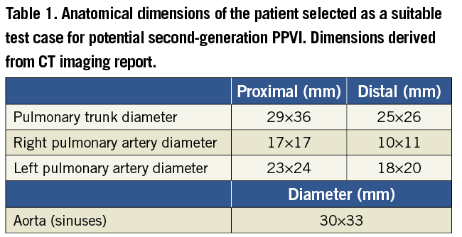
A 33-year-old male patient was selected as a suitable case study. He had severe pulmonary regurgitation and a dilated, dynamic RVOT. The morphology, dimensions and dynamics of the RVOT (Table 1) precluded a percutaneous approach with Melody™24, but this patient was considered a potential candidate for second-generation PPVI. The patient gave informed consent for use of his image data for research, as approved by the local Research Ethics Committee. The patient-specific anatomy was reconstructed from computerised tomography (CT) data processed with Mimics® software (Materialise N.V., Leuven, Belgium)24.
In vitro, the patient-specific RVOT was extruded with an arbitrary thickness of 1.5 mm and printed using TangoPlus FullCure® 930 (Figure 2C) as per the case of the cylinder. The inlet (ventricle side) and the outlet (left and right pulmonary arteries) of the RVOT were modified using cylindrical structures in order to facilitate attachment of the phantom into the mock circulatory system. The mock circuit was the same as described in the previous experiment, except PVR and pulmonary compliance were arranged in parallel (Figure 4) and equally split between the right and the left branch. PVR was set at 2 WU25,26 and compliance at 1.66 ml/mmHg27,28.
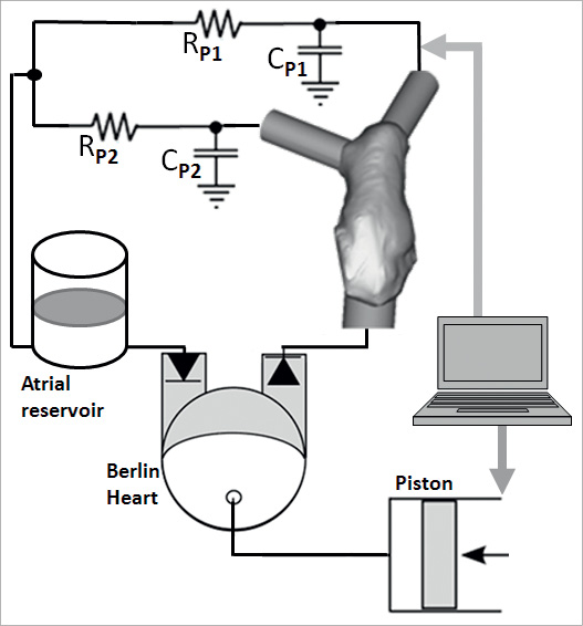
Figure 4. Schematic representation of the in vitro set-up with patient-specific rapidly prototyped model.
The delivery catheter loaded with the stent-graft was positioned inside the rapidly prototyped model and the device was released as close as possible to the bifurcation, taking care not to obstruct the branching pulmonary arteries, according to indications from an interventional cardiologist.
The system was imaged with a biplane fluoroscopy apparatus (AXIOM Artis flat-detector system; Siemens, Erlangen, Germany) to quantify 3D stent-graft deformations in the patient-specific model under pulsatile conditions (SV=40 ml, HR=50 bpm). The fluoroscopy images were processed11 to evaluate the 3D change in shape of the stent rings from the initial configuration. Three diameters were obtained for each section of the stent-graft (D1, D2 and D3 in Figure 1). The mean diameter was calculated as a parameter indicating the degree of compression of a strut with respect to the original configuration. The change from a circular to an elliptic cross-section was estimated as ratio (c) between the longest diameter and the shortest diameter amongst D1, D2 and D3.
Computationally, the same patient-specific RVOT was modelled (Figure 2F) using 60,932 hexahedral elements with the same material properties described for the cylinder and the extremities were constrained to replicate the physical boundary conditions of the mock circuit. The stent-graft FE model was crimped and released inside the RVOT, resembling the position of the in vitro experiment. Once the stent-graft was fully deployed, pressures equivalent to systolic and diastolic pressures measured in vitro (57/11 mmHg) were applied to the internal surface of the stented vessel. The quantities of interest in this simulation were also changes in stent compression and section shape (c), to be compared with the experimental case. Areas of contact on the RVOT walls were also assessed as an indication of anchoring of the device within the patient’s implantation site.
Results
Results are presented according to the level of complexity of the tests.
Boundary object material and computational model validation
The results of the compliance tests are shown in Figure 3A in terms of pressure-volume curve. The excellent correlation between in vitro measured volumes and computational calculated volumes is shown in Figure 3B (R=0.9995, p<0.0001). The Bland-Altman plot (Figure 3C) revealed a small positive systematic bias toward the computational model (mean difference between volumes= 0.16 ml).
Stent-graft computational model validation in a simplified, symmetrical geometry
The device expanded symmetrically inside the cylinder both on the bench and computationally. The diameter of the proximal ring 1 of the stent-graft was measured in vitro throughout a cycle and it oscillated between 27.6 mm at peak systole and 26.8 mm in diastole. The corresponding calculated values were 27.7 mm and 26.5 mm, as yielded from the simulations. The maximum difference between the two testing modes was 1.4%, during diastole.
Complex patient-specific computational model validation
Figure 5 shows the asymmetrical deployment of the device into the patient-specific RVOT. Successful implantation was achieved both experimentally and computationally, as shown by visual assessment of the rapidly prototyped RVOT (Figure 5A), fluoroscopy imaging (Figure 5B) and the output of the computational simulations (Figure 5C). The device sat comfortably in the anatomy; it was fully open in the central sections (i.e., ring 3, mid and ring 4) and did not obstruct the pulmonary arteries.
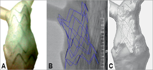
Figure 5. Stent-graft in a patient-specific model: picture of the stent-graft in the in vitro phantom (A); reconstruction of the stent-graft from fluoroscopy images obtained in vitro (B); computational model of the device released in the virtual anatomy (C).
Mean diameter and eccentricity results are shown in Figure 6 and Figure 7, respectively. The mean diameter of the expanded stent describes the degree of compression or dilation of the device compared to the initial configuration, thus indicating the degree of anchoring of the device in the patient-specific RVOT. While in the unloaded state, proximal and distal rings are equal and symmetrical, then following deployment in the patient-specific phantom and pressure application the outer rings acquire an elliptical shape (c=1.09 in systole and 1.14 in diastole for ring 1, and c=1.28 in systole and 1.38 in diastole for ring 6) with mean diameters smaller than the original device configuration (35.8 mm and 29.6 mm for ring 1 and 6, respectively, in systole), as shown in Figure 6A. The central rings not only retain a more circular cross-section (c=1.04 both in systole and in diastole for the “mid” section) compared to the outer rings, but they also undergo a smaller degree of deformation, the mean diameter of the mid section remaining effectively nearly unchanged around 22 mm (with maximum 22.3 mm in diastole), due to the lack of interaction with the RVOT.
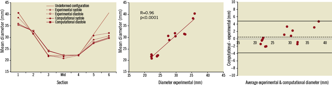
Figure 6. Variations in mean diameter (left) evaluated during systole and diastole in the in vitro and computational models, with respect to the undeformed configuration. A good correlation of experimental and computational results was achieved (centre) with no bias (0.5 mm) between the two (Bland-Altman plot, right).
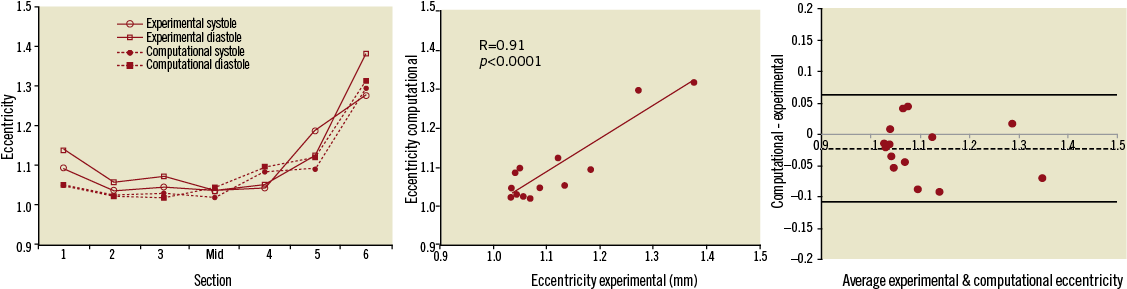
Figure 7. Variations in eccentricity (left) evaluated during systole and diastole in the in vitro and computational models, with good correlation of experimental and computational results (centre) and no bias (-0.02) between the two (Bland-Altman plot, right).
Computational results were compared with experimental values. In this case, ring 1 has a value of eccentricity of 1.05 both in systole and diastole, while the most distal ring, 6, is overall more elliptical, with c=1.29 in systole and c=1.31 in diastole. In terms of constriction and dilation of the struts, ring 6 shows a mean diameter varying from 31.9 to 30.6 mm throughout the cycle, indicating a considerable degree of compression. Observations on contact areas corroborate results regarding anchoring of the stent-graft to the RVOT, particularly in the distal position (Figure 8).
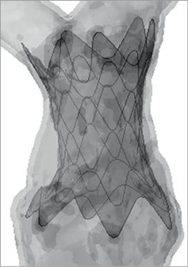
Figure 8. Areas of contact between stent-graft and patient-specific model: darker regions indicate the portions of RVOT wall in contact with the device.
Differences in mean diameter between experimental and computational results ranged from as little as 0.6% (ring 4) to 13.2% (ring 1), while differences in eccentricity ranged from 0.4% to 7.8% (ring 5). The good correlation between measured and calculated values is shown in Figure 6B and Figure 7B (R=0.96 and R=0.91 for mean diameter and eccentricity respectively, p<0.0001), with no systematic bias between computational and experimental models (Bland-Altman plots of Figure 6C and Figure 7C).
Discussion
This study presents a comparison between virtual and real bench testing of a novel percutaneous valve device. The work validates the virtual computer models against the bench testing, demonstrating that such models can also accurately represent the “real world”, thus improving confidence that they can be used to guide patient-specific treatments. This paper aimed to show not only that computational models are appealing, fast-responding tools for cardiovascular device assessment, but that the outcome of these simulations can be taken into account in a clinical context with less scepticism. This was achieved by showing good agreement between a physical, and physiologically-relevant set-up, and its computational replica, hence validating the computer model itself. Establishing this validation step is crucial in moving toward a thorough in vivo validation in larger groups of patients.
Tests were conducted in three scenarios of increasing complexity and clinical relevance. In the first case of a simple loading mode, the good agreement between computational and experimental results served the purpose of validating the numerical model of the boundary object. The material properties put into the computational model were validated against the measured distensibility, which lies in the physiological range for arteries21. In the second step, the stent-graft was deployed inside the validated FE model of the cylinder, to validate the device computational model. The diameter of the proximal ring was compared as an indication of compression under loading. Computational and experimental results were in excellent agreement, thus reinforcing the robustness of the device computational model. Finally, the validated FE stent-graft model was deployed in the reconstructed RVOT of a patient, who was selected as a potential candidate for second-generation PPVI. The material properties of the RVOT were the same as those used for the validated cylinder model.
The agreement of computational and in vitro simulations reduced with the increasing complexity of the testing mode and model. While in the first two set-ups the difference between computational and experimental results was small (equal or less than 2%), in the RVOT simulation values of mean diameter varied to a maximum of 13% and values of eccentricity up to 8%. This difference can be considered clinically acceptable and the model can thus be considered validated for a clinical application. Nonetheless, the possible reasons for this discrepancy will be analysed.
Clinical relevance
From a clinical perspective, recent data report a striking increase in the number of minimally-invasive procedures: it has been foreseen that 41% of valve replacements will be performed percutaneously in 201229. Despite this dramatic growth, clearly indicating the benefits of the percutaneous approach, complications related to the combination of device properties and patient-specific characteristics have to be addressed. A validated, hence reliable, technical tool can help this process. In this study, we have shown the clinical applicability of such methodologies by indicating that a patient regarded as unsuitable for first-generation PPVI would benefit from the implantation of a second-generation device. This result from the computational model was validated by the bench experiment, supporting the reliability of the computational findings.
Both fluoroscopy imaging of the rapidly prototyped model and the computational simulation showed that the stent-graft was satisfactorily deployed according to clinical guidelines. Indeed, to ensure successful implantation and avoid dislodgement, safe anchoring of the stent-graft to the RVOT wall has to be guaranteed with 20% reduction of the original diameter at least in one of the distal or proximal portions of the device, according to manufacturer’s indications12. This was observed both in vitro and in silico. The deployed diameters showed a marked difference in the shape of the proximal and distal rings compared to the stent’s initial geometry. Compression of the distal ring was >20% with respect to the undeformed configuration, during the cardiac cycle.
Safe anchoring is further reinforced by the distribution of areas of contact in the vessel between the outer rings and the implantation site, as shown by the computational model, which clearly demonstrates high contact in the distal region of the RVOT.
Finally, albeit the current study did not consider the presence of the valve in the stent-graft, this factor cannot be entirely disregarded. In this light, it was important to observe that the circular shape of the central rings was maintained, indicating that, were a valve present, it would be fully open and not deformed, ensuring optimal valve function. Were a valve included in the current model, it would not affect observations on device deployment and positioning, while it would permit expansion of the study of the stent-graft including observations on potential device migration and valve function. Currently, flow effects are unlikely to affect observations on device positioning, but when including a valve in the model in the future, fluid dynamics should then be investigated as potentially having more impact on the interaction between device and anatomy.
Current and future perspective
Having validated the computational model, this tool can theoretically be used with confidence to assess the suitability of future candidates referred for possible implantation of the second-generation device, if properly set to patient-specific values. In addition, the computer model allows us to test and optimise the device design according to more realistic loading conditions, to evaluate effectively the performance in both the short and long term. Despite the validation of the numerical model, in vitro tests cannot be discarded because they provide important characteristics that cannot currently be fully integrated in silico. While fluid-structure interaction (FSI) is naturally taken into account in a physical experiment, refined virtual implementation of FSI is challenging and, at present, this is the object of several complex numerical studies. A phenomenon like device migration, requiring detailed simulation of parameters such as valve leaflets movement and endothelialisation of the fabric, must still be tested in vitro or in animal experiments. Also, the clinician is still not equipped to handle a computational model in everyday practice, while the physical handling of a rapidly prototyped phantom can be more immediate24. So, while in the future a move toward full usage of a validated and user-friendly computational model might provide a powerful preclinical and clinical tool, currently a certain degree of synergy between the two modes might still be necessary.
Clinical considerations may be expanded in the future by testing the device in a larger cohort of patients, rather than in an isolated case study, which was used here for defining and detailing the validation methodology, and reinforcing the results with in vivo validation.
Limitations and methodological considerations
Both experimental and computational testing involve, to varying degrees, an approximation of the in vivo scenario. Simplifications are necessary and they can impinge on the accuracy of the real case representation and on the level of agreement between the two modes of testing.
In this study, the patient-specific approach replicates morphological characteristics, but it does not incorporate the subject’s implantation site mechanical information. Uniform wall thickness has been assumed for both the experimental and computational model. However, different portions of the RVOT may be more distensible than others, the whole structure deforming unevenly during the cardiac cycle30. In addition, the material used for rapidly prototyping the cylinder and the RVOT was not fully characterised from a mechanical point of view and consequently simple linear elastic behaviour was assumed so that computational cost was reduced. Employing a model with non-homogenous, viscous characteristics and further refinement of the modelling of the material properties would result in a more realistic simulation.
From the experimental point of view, the pressure pulse to which the stent-graft was subjected when deployed into the cylinder was very large. This input was chosen as a “worst case scenario7”, testing the deformation of the stent-graft in an extreme condition. The imposed SV is admittedly low due to a technical constraint: the left ventricular assist device (LVAD) available for in vitro tests could eject only 60 ml at maximum, and since undesired oscillations, probably due to stretching of the Berlin Heart diaphragm, were observed when operating at maximum SV, this parameter was ultimately set at 40 ml. HR is also somewhat low (50 bpm), albeit physiological, and this was purposefully chosen in order to fully appreciate the relaxation behaviour of the system (i.e., device deployed in simplified and patient-specific implantation sites).
From the computational point of view, beam elements were chosen for simulating the structures of the stent-graft, ensuring fast response in terms of analysis time. Different mesh techniques have been investigated in a separate study in order to examine in detail stress and strain distribution resulting from the stent/vessel wall interaction.
This study lacks in vivo validation, as patient data following device implantation is not yet available. The computer model, incorporating patient-specific anatomy, was not set according to patient-specific values, but according to the in vitro model, against which it was validated.
Conclusion
This study applied an experimental and computational approach based on patient-specific data to test a second-generation PPVI stent-graft, validating the in silico model against in vitro data. A satisfactorily validated computational model can be a particularly resourceful tool when studying a new device and could enhance the current standards for preclinical test. Defining safety as the avoidance of both device-related and procedural complications31, having access to reliable and inexpensive patient-specific models can refine both the process of device mechanical characterisation and patient selection for each individual case.
Acknowledgements
We gratefully acknowledge the support of the following funding bodies: Fondation Leducq, British Heart Foundation, Royal Academy of Engineering/EPSRC and the UK National Institute of Health Research. We also thank the scientists from Medtronic Cardiovascular for their technical support.
Conflict of interest statement
P. Bonhoeffer is a consultant at Medtronic Inc. The other authors have no conflict of interest to declare.
References
Online data supplement
Moving image 1. Simulation of stent-graft release in patient-specific right ventricular outflow tract and 3D navigation.