![]()
Abstract
Aims: Fully bioresorbable Absorb poly-L-lactic-acid (PLLA) scaffolds (Abbott Vascular, Santa Clara, CA, USA) are a novel approach for the treatment of coronary narrowing. Due to the translucency of the material (PLLA), the optical coherence tomography (OCT) measurement methods used in the ABSORB trials were unique but not applicable for permanent metallic stents. When the Absorb scaffold and metallic stents are compared in the context of randomised trials, it is challenging to compare the two devices using the conventional methods. The primary purpose of this report is to explain the biases in conventional methodologies applied for metallic stents and for PLLA scaffolds at baseline and follow-up, and to propose a new standard methodology that enables us to compare two different devices using an almost identical and methodological language.
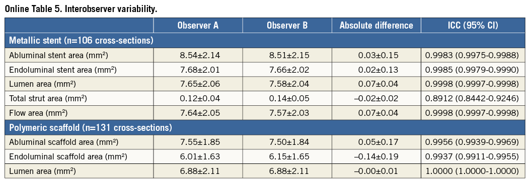
Methods and results: A consensus amongst multiple core labs and expert researchers of OCT was reached on a new standard OCT measurement methodology that enables us to compare these two different devices. In brief, the proposed OCT methods are summarised as follows. 1) Both endoluminal and abluminal scaffold/stent contours should be traced. 2) Consistently, endoluminal and abluminal incomplete stent apposition areas should be measured. 3) The area occupied by scaffold/stent struts should be quantified directly or virtually. 4) The strut area should be systematically excluded from the flow area as well as the neointimal area. 5) Additional information on the degree of embedment could be reported using the interpolated lumen contour. Interobserver variability of the proposed method was excellent (intraclass correlation 0.89-100).
Conclusions: A standardised OCT measurement methodology is proposed. This should be implemented in ongoing and future trials comparing the Absorb scaffolds and metallic stents.
Introduction
The implantation of a bioresorbable scaffold (BRS) is a new approach that provides transient vessel support with drug delivery capability, potentially without the limitations of permanent metallic implants1. The potential short- and long-term performance of this technology has been repeatedly investigated with optical coherence tomography (OCT)2-7. However, images acquired by OCT after implantation of BRS are different from those with metallic stents due to the translucency of polymeric materials compared to the opacity of metallic compounds8 (Figure 1). Metallic struts appear on OCT as a reflective leading structure with abluminal shadowing, while polymeric struts appear as a “black box” area surrounded by bright reflecting frames without abluminal shadowing. As a consequence, in polymeric scaffolds the vessel wall behind the struts and the luminal area can easily be imaged and assessed, contributing to several advantages in quantitative analysis: i) capability of measuring the lumen vessel wall interface at baseline; ii) accurate assessment of malapposed struts; iii) measurement of strut/strut core area; iv) precise measurements of flow area; v) measurement of neointimal area between and on top of the struts, resembling very much the histomorphometric analysis of the animal models at follow-up.
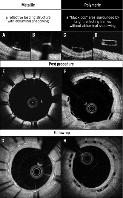
Figure 1. The inherent differences between metallic stents and polymeric scaffolds on OCT. Representative appearance of metallic and polymeric struts is shown in A-D. Cross-sections post procedure with well-apposed struts (E and F) and those at follow-up (G and H) are illustrated.
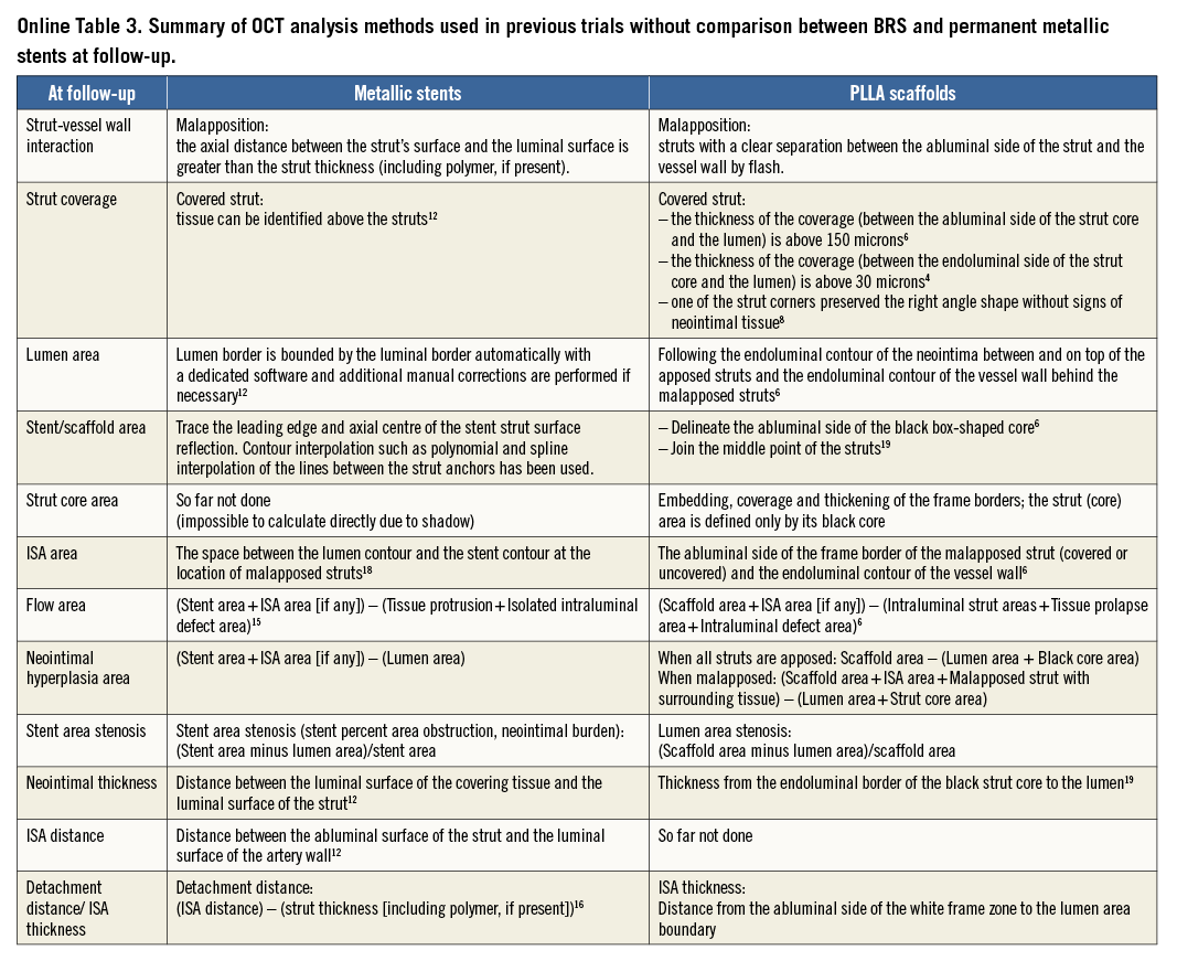
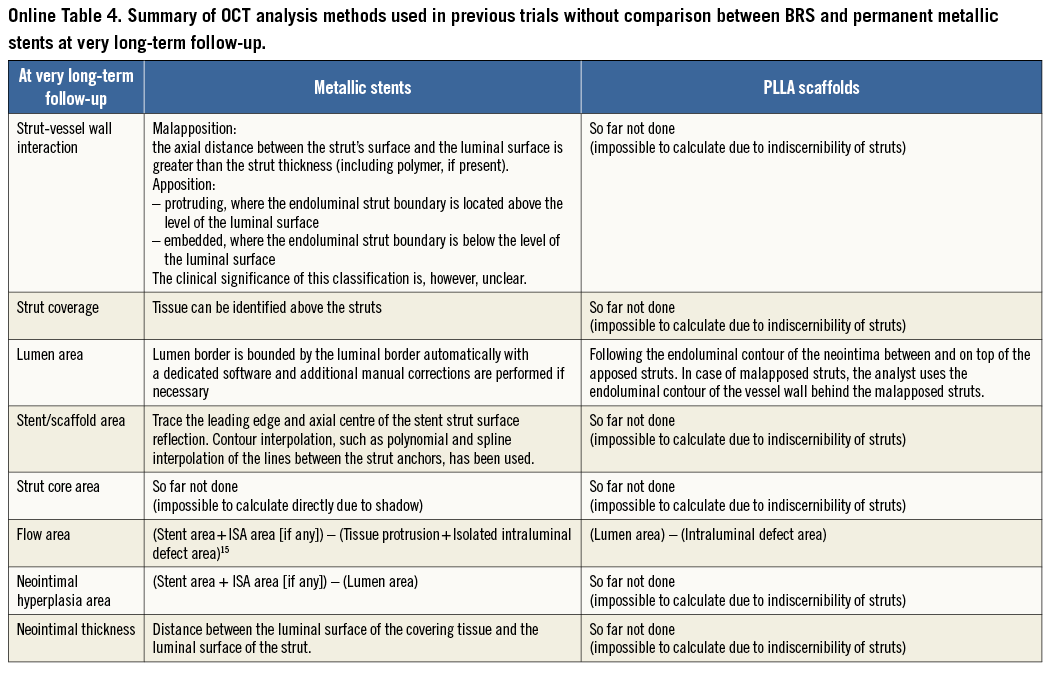
In previous ABSORB studies of polymeric scaffolds without comparison with metallic stents, OCT methods were developed to take advantage of the optical properties of poly-L-lactic-acid (PLLA); however, some of these were not applicable to metallic stents. For example, strut core area is not directly measurable in metallic stents. Taking into account the fact that many randomised trials comparing BRS and metallic stents with imaging endpoints are still ongoing9 (Online Table 1), it is important to establish a standardised and comparative method for quantitative analysis on OCT.
The primary purpose of this report is to explain differences in the conventional methodologies applied to metallic stents and PLLA scaffolds (specifically for the Absorb scaffold; Abbott Vascular, Santa Clara, CA, USA) at various time points, and to present the consensus of multiple core labs and OCT experts on a new standard methodology that enables us to compare two different devices using an almost identical, methodological language.
Potential biases caused by application of conventional methods
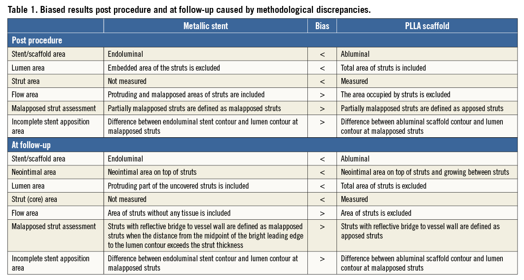
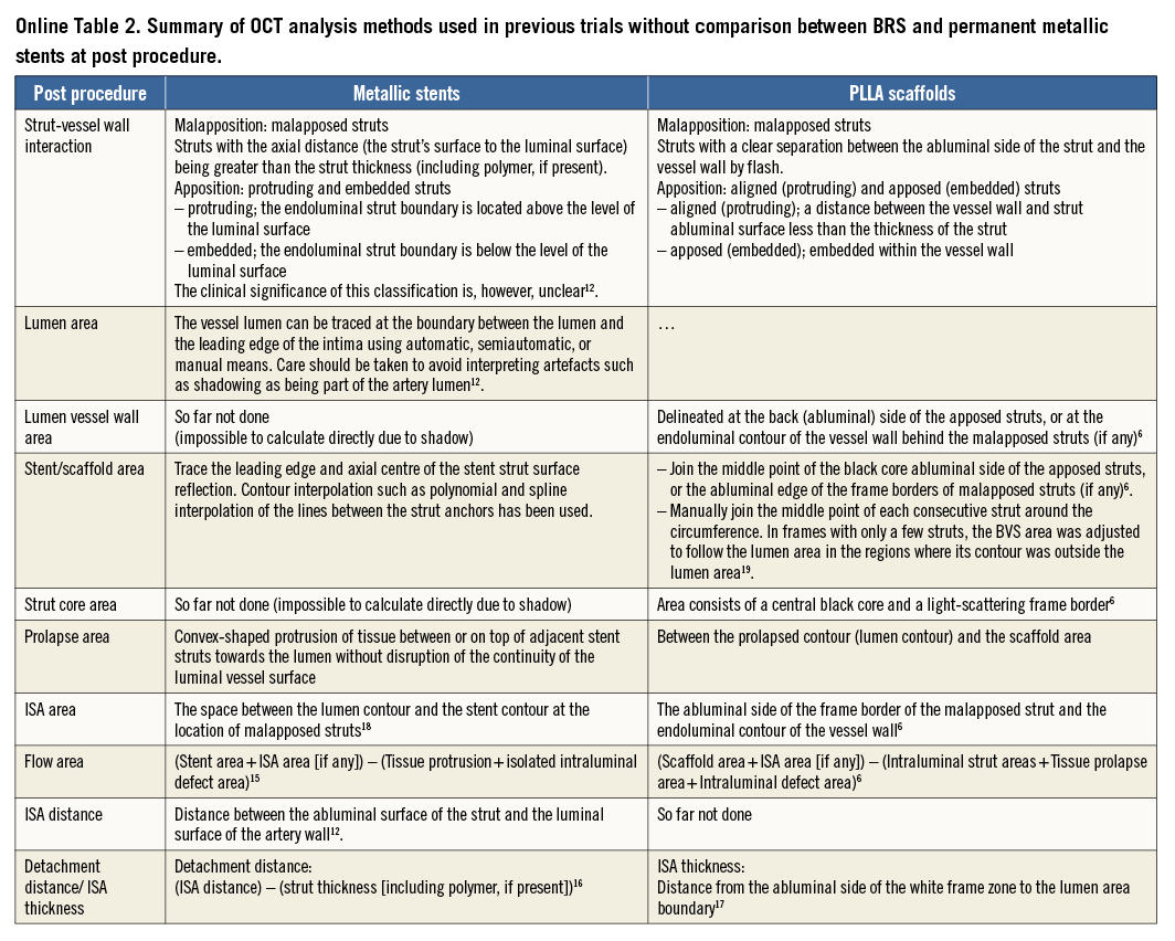
The basic differences in the two OCT measurement methods for polymeric struts and metallic stents stem from the translucency of the polymeric device. The conventional bioresorbable methodology provides more parameters than metallic methods: the area occupied by the struts and tracing of the back of struts. These parameters influence the measurement and calculation of the scaffold area, lumen area, total strut area, flow area, and malapposition area. In some parameters (e.g., flow area), the conventional metallic methods are incomplete in that the strut area is ignored. When the conventional methods (Online Table 2-Online Table 4) are applied for the comparison of the polymeric bioresorbable scaffold and the permanent metallic stents, the following methodological discrepancies lead to biased results post procedure and at follow-up (Table 1).
STENT (ENDOLUMINAL)/SCAFFOLD (ABLUMINAL) AREA
Post procedure (Figure 2), in metallic stents, the stent area is typically measured by interpolated contours connecting the endoluminal edge of the reflective border10-14. In polymeric scaffolds, the scaffold area is measured by interpolated contours connecting the abluminal side of black strut cores6. The scaffold area of polymeric devices (abluminal) is expected to be systematically larger than the stent area of metallic devices (endoluminal).
Theoretically speaking, when a 3.0 mm Absorb device with a strut thickness of 150 μm is deployed perfectly at the nominal size, endoluminal device area and abluminal device area are 7.07 mm2 and 8.54 mm2, respectively. In the clinical cases where the endoluminal stent area and endoluminal scaffold area are identical (7.07 mm2), the conventional stent area is measured on OCT as 7.07 mm2, while the abluminal scaffold area is measured as 8.98 mm2 (Figure 2). This causes the difference in reporting the stent/scaffold area of approximately 2 mm2. The same is applicable to the follow-up up to three years. At a very long-term follow-up (>4 years), the scaffold area becomes difficult to measure due to the complete integration (disappearance) of the polymeric struts.
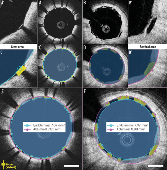
Figure 2. Differences in endoluminal and abluminal stent area between metallic and polymeric struts. Metallic struts and polymeric struts post procedure are shown in A and B. Conventional measurements of stent/scaffold area are indicated in C and D. A’-D’ show magnified views of A-D. In the cases where the endoluminal stent area and endoluminal scaffold area are identical (7.07 mm2), conventional stent area is measured as 7.07 mm2 (E), while abluminal scaffold area is measured as 8.98 mm2 (F).
LUMEN AREA
The lumen area measured with BRS methods includes the entire strut area, while the lumen area with metallic methods excludes some of the strut area. Therefore, the lumen area by BRS methods tends to be larger than that by metallic methods (0.42 mm2 on average)6.
Post procedure (Figure 3), the luminal contour of metallic stents is generally traced somewhat behind the apposed strut and interpolated through the struts virtually10-14. The embedded part of the metallic strut is excluded from the lumen area measurement. In polymeric devices, the embedded part of the polymeric strut (struts not buried) is fully included in the lumen area measurement.
At follow-up (Figure 4), the two methods do not cause discrepancy as long as all struts are apposed and covered. In the presence of uncovered metallic struts, the metallic lumen area tends to be smaller since the uncovered struts are excluded from the lumen.
TOTAL STRUT AREA
The abluminal edge of metallic struts cannot be visualised on OCT imaging due to the outer shadow. Therefore, the area occupied by metallic struts has not been quantified and taken into account in any measurements. In polymeric scaffolds, two areas have been measured for individual struts: i) total strut area (tracing the outer boundary of the bright reflective frame), and ii) strut core area (tracing the black core)6. This inconsistency affects the lumen and flow area measurement both post procedure (Figure 3) and at follow-up (Figure 4).
FLOW AREA
The flow area of metallic methods tends to be larger than that of BRS methods in the presence of malapposed struts6,15. Flow area is defined as the cross-sectional area where the blood flows. This excludes any intraluminal structures (such as thrombus, malapposed struts, and their surrounding neointimal tissue). In metallic struts, due to the lack of direct measurement of metallic strut areas, the malapposed struts and surrounding tissues are typically included (Figure 3).
MALAPPOSED STRUT ASSESSMENT
Post procedure (Figure 3) and at follow-up (Figure 4), the frequency of malapposed struts is potentially overestimated with the metallic methods compared to BRS methods. In the metallic stents, the struts are judged as malapposed when the distance from the midpoint of the bright leading edge to the interpolated lumen contour exceeds the strut thickness (including polymer, if present) as provided by the manufacturer10-14,16-18. In this method, partially malapposed struts (a part of the strut is in contact with the vessel wall, which is invisible due to outer shadow) are counted as malapposed struts. In polymeric devices, the contact of struts with the vessel wall is directly visible6,19. When any part of the struts is touching the vessel wall, the struts are judged as apposed.
At follow-up (Figure 4), with polymeric devices, when any part of the struts is connected to the vessel wall by an abluminal connecting bridge, a lateral connecting bridge or a bilateral connecting bridge (directly visible), the struts are judged as apposed6. With metallic stents, the back of the struts is invisible, so that, in the presence or absence of an abluminal connecting bridge, the struts are always judged as malapposed.
INCOMPLETE STENT APPOSITION AREA
Due to the discrepancy of the methods, the incomplete stent apposition (ISA) area in the polymeric scaffold is expected to be systematically smaller than that in the metallic stent both post procedure (Figure 3) and at follow-up (Figure 4). Post procedure, in metallic stents, the ISA area is defined as the area between the endoluminal leading edge of the metallic struts and the lumen contour at the site of malapposed struts20. In polymeric scaffolds, this is defined as the area between the scaffold (abluminal) and the lumen contour6,21.
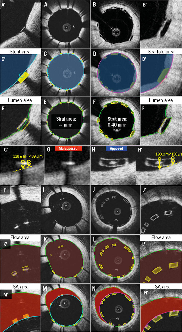
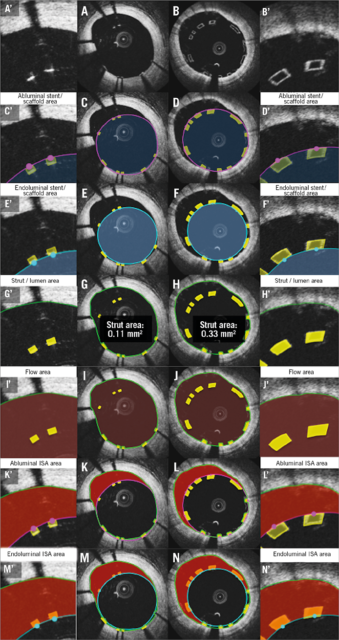
Figure 3. Potential biases caused by application of conventional methods post procedure. Representative cross-sections of apposed struts, stent/scaffold area measurement, lumen area measurement, apposition of struts, ISA, flow area measurement, and ISA area measurement are shown in A, C, E, G, I, K, M (metallic stents) and B, D, F, H, J, L, N (polymeric struts), respectively. A’-N’ are magnified views of A-N.
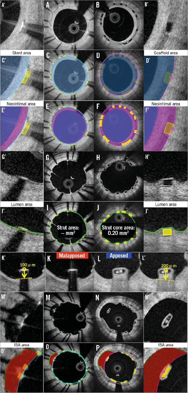
Figure 4. Potential biases caused by application of conventional methods at follow-up. Representative cross-sections of covered struts, stent/scaffold area measurement, neointimal area measurement, uncovered struts, strut area or strut core area measurement, apposition of struts, ISA, ISA area measurement are shown in A, C, E, G, I, K, M, O (metallic stents) and B, D, F, H, J, L, N, P (polymeric struts), respectively. A’-P’ are magnified views of A-P.
NEOINTIMAL AREA
The neointimal area measurement in metallic stents is expected to be systematically smaller than that of polymeric scaffolds (Figure 4). Metallic methods quantify the neointima on top of the struts, but ignore the neointima growing between the struts as well as the neointima surrounding the malapposed strut. In polymeric devices6,21, the neointima growing between the strut and the neointima surrounding the malapposed strut are included in the neointimal area measurement.
Proposed comparative measurement methods
To minimise/eliminate the discrepancy in measurement and reporting due to the difference in measurement, the following measurement methods are proposed in consensus amongst core labs and expert researchers. The most important changes are: standardisation of device area measurement (abluminal or endoluminal) and the direct or virtual measurement of the area occupied by struts.
STENT/SCAFFOLD AREA
ABLUMINAL STENT/SCAFFOLD AREA
The measurement of abluminal device area represents the area of the device that interacts with the vessel wall. Furthermore, it will give the baseline landmark in measurement of a neointimal hyperplasia between and on top of the struts. In polymeric scaffolds, the abluminal scaffold contour is drawn by joining the midpoint of the abluminal side of the black core in the apposed struts (Figure 5, Figure 6), or the abluminal edge of the reflective frame borders of malapposed struts (Online Figure 1).
Post procedure (Figure 5) and at follow-up (Figure 6), in metallic stents, the abluminal stent contour cannot be directly delineated; however, this can be automatically drawn by simulating the virtual contour of the struts. After identifying all struts in a cross-section, the abluminal stent contour is delineated by a curvilinear interpolation connecting the middle points of the abluminal edge of virtual metallic struts.
ENDOLUMINAL STENT/SCAFFOLD AREA
Measurement of the endoluminal device area enables a direct comparison of the internal dimensions of the device. The endoluminal metallic stent contour is delineated by a curvilinear interpolation connecting the midpoints of the endoluminal leading edge of the reflective border (Figure 5). At follow-up, the bright leading edge of the metallic strut is generally still detectable in the neointima (Figure 6).
The endoluminal polymeric scaffold contour is delineated by a curvilinear interpolation connecting the midpoint of the endoluminal side of the reflective frame. Whenever the polymeric reflective frame is not discernible, such as with buried struts in the vessel wall post procedure or struts at follow-up, there is no other alternative and the leading edge of the black box in polymeric struts has to be compared with the bright leading edge of the metallic struts (Figure 6).
LUMEN AREA
Lumen contour is defined as the continuous interface between a blood and non-blood structure. Since any intraluminal structures isolated in the blood area are measured separately, the lumen area does not primarily exclude them (intraluminal mass and isolated malapposed struts not connected to the vessel wall by a bridge) (Figure 5, Online Figure 1).

Figure 5. Proposed comparative analysis methods post procedure in the cross-section without malapposed struts. Representative cross-sections with well-apposed metallic struts and polymeric struts are shown in A and B. Comparative methods of abluminal stent/scaffold area, endoluminal stent/scaffold area, strut area/lumen area, and flow area are illustrated in C, E, G, I (metallic strut), and D, F, H, J (polymeric strut), respectively. A’-J’ are magnified views of A-J.
At follow-up, when the side-to-side bridge divides the vessel into a double channel lumen, the second lumen behind the bridge should be included in flow area measurement (Figure 6, Online Figure 2, Online Figure 3).
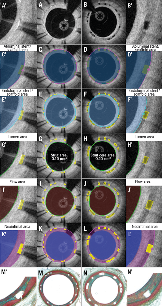
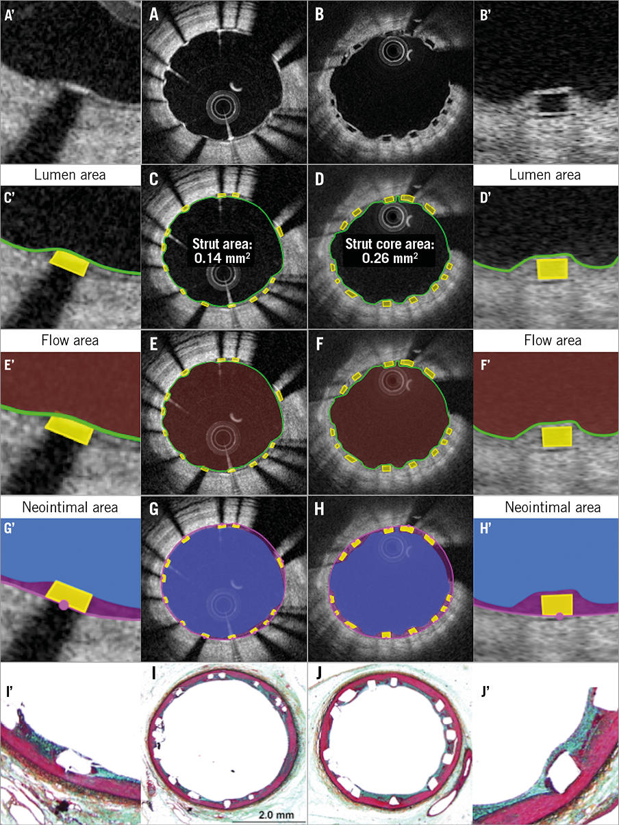
Figure 6. Proposed comparative analysis methods at follow-up in the cross-section of covered struts without malapposed struts. Representative cross-sections with well-covered metallic and polymeric struts at follow-up are shown in A and B, respectively. Abluminal stent/scaffold area, endoluminal stent/scaffold area, lumen area, flow area, and neointimal area are shown in C, E, G, I, K (metallic strut), and D, F, H, J, L (polymeric strut), respectively. Histomorphometric analyses of the animal models are shown in M (metallic strut) and N (polymeric strut). A’-N’ are magnified views of A-N.
MALAPPOSED STRUTS
In general, when the distance between the endoluminal surfaces of struts with respect to the interpolated lumen contour is more than the strut thickness, either metallic or polymeric, the strut is considered as a malapposed strut. It is measured at the midpoint of the endoluminal reflective border of metallic stents or the endoluminal side of the reflective frame of polymeric scaffolds (Online Figure 4).
Post procedure, the malapposition distance is the distance between the interpolated (made necessary by the metal shadowing) lumen contour and the back of the completely malapposed metallic or polymeric struts (abluminal reflective frame in polymeric struts and virtual back [=89 µm from the bright leading edge] in metallic [XIENCE®; Abbott Vascular] struts) at the midpoint of the endoluminal edge of the strut. A malapposition distance greater than zero is the criterion of malapposition. Whenever the back of polymeric or metallic struts (virtual back) is in contact with the (interpolated) lumen contour, the malapposition is characterised as partial. Even in case of partial malapposition, the malapposition distance can be measured.
At follow-up, in polymeric scaffolds, the abluminal side of the black core is used for the measurement of malapposed distance, since the abluminal reflective bright frame cannot be distinguished from the neointima coverage.
In recent core lab experiences, we have observed on follow-up OCT that malapposed struts are sometimes connected with the vessel wall by tissue created behind the struts or between the struts and vessel wall unilaterally or bilaterally. This aspect should be described and classified according to the type of connecting bridge (Online Figure 4): i) malapposed struts without connecting bridge (isolated malapposed strut), ii) malapposed struts with a potentially thin abluminal connecting bridge, which could be masked by the shadow in metallic struts, iii) malapposed struts with an abluminal connecting bridge, iv) malapposed struts with a lateral connecting bridge, v) malapposed struts with a bilateral connecting bridge.
INCOMPLETE STENT APPOSITION AREA
The ISA area is a part of the blood flow area located behind the malapposed struts. The delineation of the abluminal side of the ISA area is usually drawn as the same as the scaffold/stent area. As described above, when the scaffold/stent area is drawn using the endoluminal and/or abluminal contours, the same principle should be applied for measurement of the ISA area.
ABLUMINAL INCOMPLETE STENT APPOSITION AREA
Abluminal ISA area is the difference between the abluminal stent/scaffold area and the lumen area at the site of malapposed metallic/polymeric struts (Online Figure 1, Online Figure 3). Although we could use endoluminal/abluminal ISA area, we favour the use of abluminal ISA area for consistency with the measurement of the flow area.
ENDOLUMINAL INCOMPLETE STENT APPOSITION AREA
Endoluminal ISA area is the difference between the endoluminal scaffold/stent area (see previous definition) and the lumen area at the site of malapposed polymeric/metallic struts (Online Figure 1, Online Figure 3).
PROLAPSE AREA
Post procedure, prolapse is a protrusion of the vessel wall structure between or on top of adjacent stent struts beyond the endoluminal stent/scaffold contour without disruption of the continuity of the lumen vessel surface22 (modified from the previously published methodology23). At follow-up, this area is measured as a part of the neointima.
INTRALUMINAL DEFECT AREA
An irregularly shaped structure in contact with the luminal contour is defined as an intraluminal defect attached to the vessel wall. The area of defect can be measured. An isolated structure in the lumen distant from the vessel wall is defined as a free intraluminal defect.
FLOW AREA
In order systematically to exclude the intraluminal structures attached to or free from the vessel wall, the measurement of malapposed struts with surrounding tissue is mandatory, either with direct measurement or by virtual simulation of the metallic strut area. The flow area can be calculated using the following formula: (lumen area [see the previous definition]) (second lumen area [if any]) - (intraluminal structures area [e.g., isolated intraluminal defect area, strut area of malapposed strut without surrounding tissue and malapposed strut with surrounding tissues not connected to the vessel wall including strut area, if any]) (Figure 5, Figure 6, Online Figure 1-Online Figure 3).
ASSESSMENT OF THE INTERACTION BETWEEN THE STRUTS AND VESSEL WALL USING THE INTERPOLATED LUMEN CONTOUR
In order to assess the strut-vessel wall interaction, the interpolated contour should be drawn at the site where the metallic or polymeric struts are embedded inside the vessel wall level. In case of a single protruding or malapposed strut, a short linear interpolation between the two edges should be used. In case of multi-strut extensive malapposition, a curvilinear interpolation should be used (Online Figure 4).
Post procedure, this contour interpolates through the protruding metallic or polymeric struts. At follow-up, this contour should keep circularity and interpolate through the uncovered struts and the connecting reflective bridge of malapposed struts. However, it should be noted that the interpolated contour is the line of the lumen vessel wall virtually interpolated through the struts. Therefore, the area measurement according to this contour has no meaning from the biological point of view, but reflects the vessel wall injury.
Using the interpolated lumen contour, malapposition and the degree of embedment are assessed per strut (Figure 7). The degree of embedment could be the parameter of the vessel injury caused by the implantation of the scaffold/stent struts. Notably, the current BRS has a larger surface (Absorb: 26%) area compared to metallic stents (XIENCE: 12%). When the same force is applied, BRS struts create less pressure compared to metallic struts, which could result in less embedment of BRS struts24. Therefore, the reporting of the degree of embedment could be important to describe the difference in device-vessel interaction.
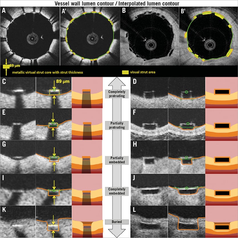
Figure 7. Assessment of the interaction between the struts and the vessel wall. Representative cross-sections with well-apposed metallic struts and polymeric struts are shown in A and B. A’ and B’ show the strut area measurement and interpolated lumen contour. Definitions of embedment based on the distance between strut and interpolated lumen contour are shown in C-L. Completely protruding, partially protruding, partially embedded, completely embedded, and buried struts are shown in C, E, G, I, K (metallic struts), and D, F, H, J, L (polymeric struts), respectively.
The degree of embedment (in percentage) could be calculated using the following formula: (1–[the distance between the midpoint of the endolumnal strut surface to the interpolated lumen contour]/[the thickness of the strut (as indicated by the manufacturer)])×100 (%). Complete protruding is defined as the (virtual) abluminal surface of metallic or polymeric struts being aligned with the interpolated lumen contour line (i.e., 0% embedment). When the degree of the embedment is between 0% and 50%, the strut is classified as partially protruding. When the degree is between 50% and 100%, such struts are categorised as partially embedded. Complete embedment is defined as the endoluminal surface of metallic or polymeric struts being aligned with the interpolated lumen contour line (i.e., 100% embedment). When the tissue is covering the endoluminal surface of struts, the struts are considered as buried.
Vessel wall lumen contour implicates the whole vessel wall which consists of a three-layer structure (intima, media, adventitia); these structures are deformed during stent/scaffold implantation, and therefore the vessel wall lumen contour should be drawn behind the abluminal side of metallic struts (virtual contour, taking into account the strut thickness) or the scaffold strut (visible contour of black core) at the site of apposed struts.
NEOINTIMAL AREA
After an implantation of a coronary device, neointimal tissue grows not only on top of the struts but also between the struts as a response to the acute injury. In histomorphometry, the amount of neointimal tissue between the struts is quantified using the internal elastic membrane (IEM). On OCT, the abluminal scaffold/stent contour measured directly or virtually could serve as a landmark indicating the original lumen border (surrogate for an IEM), which enables quantification of a neointimal hyperplasia as in histomorphometry (Figure 6).
When all struts are apposed, the neointimal area is calculated as: (abluminal stent/scaffold area) - (lumen area+strut/strut core area). With this comparative method, the areas occupied by the metallic or polymeric struts are excluded, and the neointima between and on top of the struts is quantified. In the presence of any malapposed struts, there is a need to introduce the concept of a hybrid area, consisting of a combination of scaffold contour and lumen contour (Online Figure 3). The hybrid area is delineated by the abluminal side of the struts (abluminal stent/scaffold contour) of the apposed struts and by the interpolated lumen contour at malapposed struts (interpolated contour). According to these measurements, the neointimal area is calculated as: ([hybrid area] – [lumen area] – [apposed strut/strut core area])+([isolated malapposed strut with surrounding tissues area] – [malapposed strut/strut core area]).
The presence of neointima between struts could be described (covered strut with complete inter-strut neointima, covered strut with incomplete inter-strut neointima, uncovered strut with complete inter-strut neointima and uncovered strut with incomplete inter-strut neointima) (Online Figure 5).
STRUT COVERAGE
Coverage of polymeric struts and metallic stents should be assessed using different criteria. Typically, on OCT the polymeric struts look like black boxes surrounded by a bright frame, which is the interface between the blood and PDLLA/PLLA. Immediately after the implantation in vivo of BRS, the thickness of the endoluminal bright border is measured as 30 μm on average4. The light intensity of neointimal tissue is similar to the bright border, and they are indistinguishable on visual assessment. Any tissue coverage on top of the struts should result in an increase of the thickness of the bright border: therefore, the threshold of coverage thickness ≥30 μm should be used to assess the coverage of the polymeric struts.
Regarding metallic struts, the coverage thickness of >0 μm (tissue can be identified above the struts) should be used to classify covered and uncovered struts.
In malapposed struts without an abluminal connecting bridge, the coverage of the abluminal strut side should be assessed. The neointimal abluminal coverage at the back of the metallic or polymeric strut does not reflect the initial degree of malapposition, but reflects a biological attempt to create a connecting bridge between the struts and the lumen interface.
The coverage thickness (neointimal thickness on top of struts) is defined as the distance between the luminal surface of the covering tissue and endoluminal reflective edge in metallic struts or endoluminal side of the black core in polymeric struts. In malapposed struts, it is possible to measure the thickness of the abluminal neointima.
In malapposed struts without an abluminal connecting bridge, the neointimal thickness should be measured on both the abluminal and endoluminal sides. The endoluminal neointimal thickness is defined as the distance from the abluminal side of the strut (abluminal side of the black core in a polymeric strut or that of a virtual strut in a metallic stent) to the neointima-lumen interface, following a straight line connecting the midpoint of the longitudinal axis of the strut with the centre of gravity of the lumen. The reason why we use the back of metallic or polymeric struts is to take into account the initial degree of malapposition post procedure.
The reproducibility data of the proposed method are additionally presented in terms of mean abluminal stent area, mean endoluminal stent area, mean lumen area, mean flow area, and mean total strut area. The interobserver variability showed excellent correlation of the two measurements with an ICC ranging from 0.89 to 1.00 (Online Table 5, Online Figure 6).
Discussion
In short, the proposed OCT methods are summarised as follows. 1) Both endoluminal and abluminal scaffold/stent contours should be traced. 2) Consistently, endoluminal and abluminal ISA area should be measured. 3) The area occupied by scaffold/stent struts should be quantified directly or virtually. 4) The strut area should be systematically excluded from the flow area as well as the neointimal area. 5) Additional information on the degree of embedment could be reported using the interpolated lumen contour.
The proposed new method is applicable specifically for the Absorb scaffolds, and in general for metallic stents. Amongst PLLA-based scaffolds, there is considerable variance in the initial molecular weight, the presence of a copolymer, the purity of PLLA (monomer, solvent) and post-processing methods (extrusion, annealing, microbraiding, etc.), which could influence the bioresorption time and optical properties of struts (OCT imaging). For example, the same methods could be used at baseline for the other PLLA devices such as ART® BRS (Arterial Remodeling Technologies, Noisy-le-Roi, France), Amaranth FORTITUDE® (Amaranth Medical, Inc., CA, USA), and DESolve® (Elixir Medical, Sunnyvale, CA, USA) but not for the Mirage PLLA scaffold (ManLi Cardiology, Singapore). On OCT, the strut of the Mirage scaffold is bright at implantation, and therefore OCT cannot measure its dimensions. Regarding the ART, Amaranth and DESolve scaffolds, the proposed methods may not be applicable at follow-up due to the different resorption times. The general concept of measuring endoluminal and abluminal scaffold contours and strut area should be applied for the other PLLA technologies, but the details of analysis (follow-up method) should be fine-tuned for each individual device.
In metallic stents, it could be challenging to simulate the area occupied by a strut and the location of the abluminal surface of the strut by drawing a virtual square with a length that is equivalent to the known strut plus polymer (if present) thickness. To the best of our knowledge, we do not have commercially available software that enables us to depict the abluminal metallic stent contour with the strut thickness automatically, which could result in limited reproducibility in the measurements. In addition, the virtual metallic struts should be drawn considering the limitations of OCT images in the following cross-sections: i) in the cross-section with suboptimal flushing, the stent struts are illustrated as blurred and enlarged due to the low lateral resolution, ii) in the cross-section when the OCT catheter is located towards one side of the vessel, the stent struts appear to face the catheter (strut orientation artefact)13.
After the integration of a bioresorbable scaffold to the vessel wall, we can no longer use the measurement of scaffold area, neointimal area and ISA area (if present), and at long-term follow-up we can only compare the flow area between metallic stents and bioresorbable scaffolds. We therefore emphasise the accurate measurement of flow area in the currently proposed methods. In the conventional analysis method of metallic stents, the flow area is calculated based on the lumen contour, which is the virtually interpolated contour through the struts, resulting in inaccurate measurement of flow area. In the currently proposed method, this interpolated contour enables us to assess the malapposed or apposed struts.
Limitations
In other BRS made of magnesium or iron, the proposed method for metallic stents could be applied post procedure but not at follow-up. In BRS made of a fully bioresorbable polymer with a different optical property due to the different material or post-processing such as microbraiding, some proposed methods cannot be applied. However, even in BRS where the abluminal side of the struts is not discernible, some interpolation (abluminal side is drawn virtually to simulate the thickness of the strut) could be applied. The bright reflective border of the polymeric struts is not distinguishable from the vessel neointima at the follow-up phase, so that measuring the black core area might slightly underestimate the strut area. In the presence of the blooming and/or sunflower artefact13 of metallic struts, it remains challenging for technology to measure accurately the metallic stent area.
Conclusion
When conventional methods are applied for the comparison of polymeric scaffolds and permanent metallic stents, the different methodological approaches lead to biased results post procedure and at follow-up. By introducing the virtual square of metallic struts, the proposed method enables us to compare topologically the two different devices.
| Impact on daily practice In the ABSORB first-in-man trials testing an everolimus-eluting bioresorbable scaffold, the optical coherence tomography analysis was performed with a unique methodology taking advantage of the translucency of the material (PLLA); however, such methods could not be applied to permanent metallic stents. In this report, the authors describe differences in conventional methodologies applied for metallic stents and PLLA scaffolds at various time points, assess a potential impact on measurement by applying heterogeneous methods, and propose a new standard methodology that enables us to compare two different devices using an almost identical, methodological language. This standardised OCT measurement methodology should be implemented in the ongoing and future trials comparing the Absorb scaffolds and metallic stents, enabling us to make a fair evaluation of the performance of both devices. |
Guest Editor
This paper was guest edited by Giulio Guagliumi, MD; Cardiovascular Department, Ospedali Riuniti di Bergamo, Bergamo, Italy.
Conflict of interest statement
E. Regar receives research support from St. Jude Medical to the institution. M.D. Radu receives speaker honoraria from St. Jude Medical. L. Räber receives speaker bureau and an unrestricted research grant to the institution from St. Jude Medical. F. Prati is a consultant of St. Jude Medical. T. Kimura is a member of the Advisory Board for Abbott Vascular and receives a research grant. K. Kozuma is a member of the Advisory Board for Abbott Vascular Japan and receives lecture fees. K. Tanabe is a member of the Advisory Board for Abbott Vascular Japan, a consultant of Terumo, Kaneka and Zeon, and receives remuneration from St. Jude Medical. C. Di Mario receives a research grant from Abbott Vascular to the institution. P.W. Serruys is a member of the Advisory Board for Abbott Vascular. Y. Onuma is a member of the Advisory Board for Abbott Vascular. The other authors have no conflicts of interest to declare. The Guest Editor is a consultant for St. Jude Medical and Boston Scientific and received research grants through the hospital from Abbott Vascular, Boston Scientific and St. Jude Medical.
Supplementary data

Online Figure 1. Proposed comparative analysis methods post procedure in the presence of malapposed struts. Representative cross-sections with malapposed metallic struts and polymeric struts are shown in A and B. Comparative methods of abluminal stent/scaffold area, endoluminal stent/scaffold area, strut area/lumen area, flow area, endoluminal ISA area, and abluminal ISA area are illustrated in C, E, G, I, K, M (metallic strut), and D, F, H, J, L, N (polymeric strut), respectively. A’-N’ are magnified views of A-N.
Online Figure 2. Proposed comparative analysis methods at follow-up in cross-section in the presence of uncovered struts. Representative cross-sections with uncovered metallic and polymeric struts at follow-up are shown in A and B, respectively. Lumen area, flow area, and neointimal area are shown in C, E, G (metallic strut) and D, F, H (polymeric strut), respectively. Histomorphometric analyses of the animal models are shown in I (metallic strut) and J (polymeric strut). A’-J’ are magnified views of A-J.
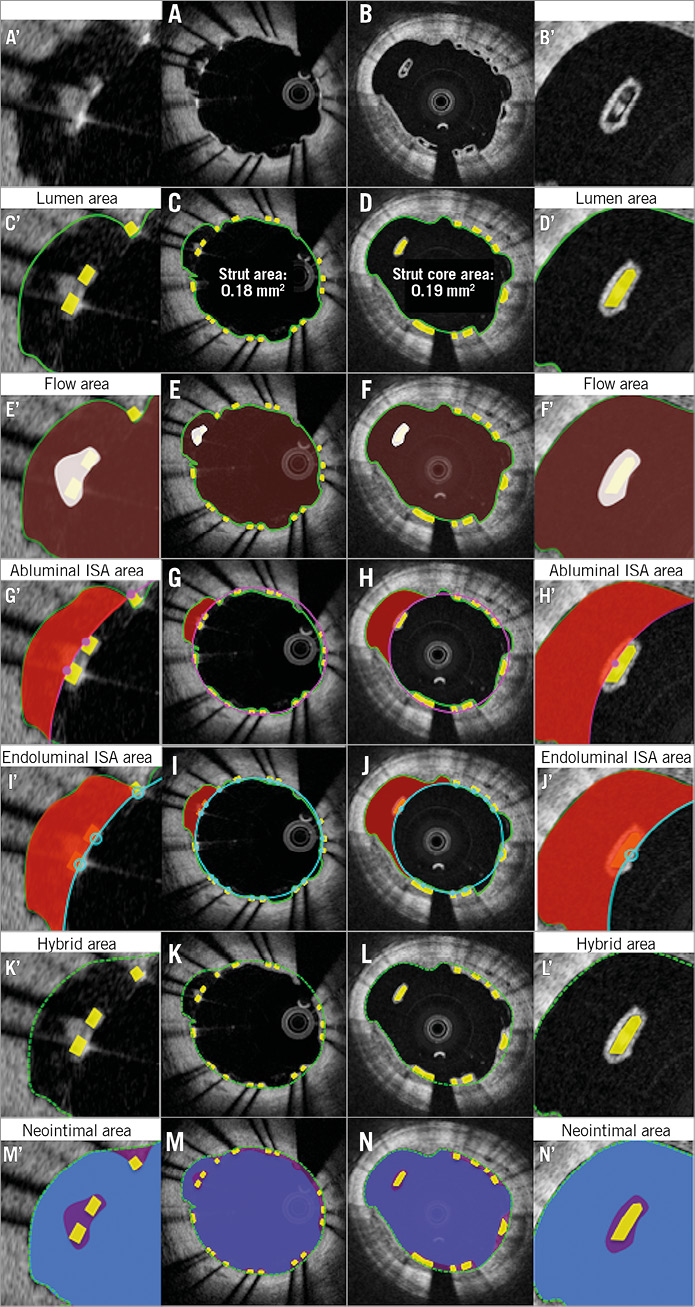
Online Figure 3. Proposed comparative analysis methods at follow-up in the presence of malapposed struts. Representative cross-sections with malapposed metallic and polymeric struts at follow-up are shown in A and B, respectively. Lumen area, flow area, abluminal ISA area, endoluminal ISA area, hybrid area, neointimal area are shown in C, E, G, I, K, M (metallic strut) and D, F, H, J, L, N (polymeric strut), respectively. A’-N’ are magnified views of A-N.
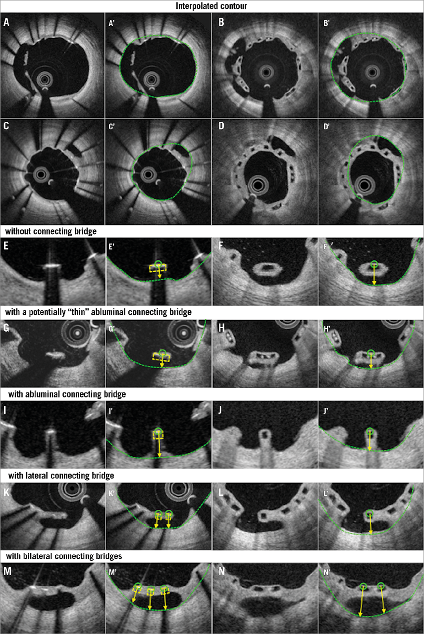
Online Figure 4. Proposed assessment of malapposed struts at follow-up. Representative cross-sections with malapposed metallic and polymeric struts at follow-up are shown in A and B, respectively. Classifications of malapposed struts are displayed in E-N. Malapposed struts without connecting bridge, those with a potentially thin abluminal connecting bridge, those with an abluminal connecting bridge, those with a lateral connecting bridge, and those with bilateral connecting bridges are shown in E, G, I, K, M (metallic strut), and F, H, J, L, N (polymeric strut), respectively. A’-N’ display interpolated contours of A-N.
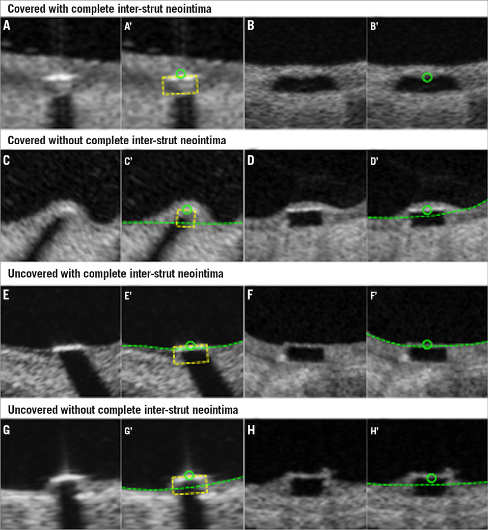
Online Figure 5. Assessment of strut coverage. Covered strut with complete inter-strut neointima (A and B), covered strut with incomplete inter-strut neointima (C and D), uncovered strut with complete inter-strut neointima (E and F), and uncovered strut with incomplete inter-strut neointima (G and H) are displayed. A’-H’ display interpolated contours of A-H.
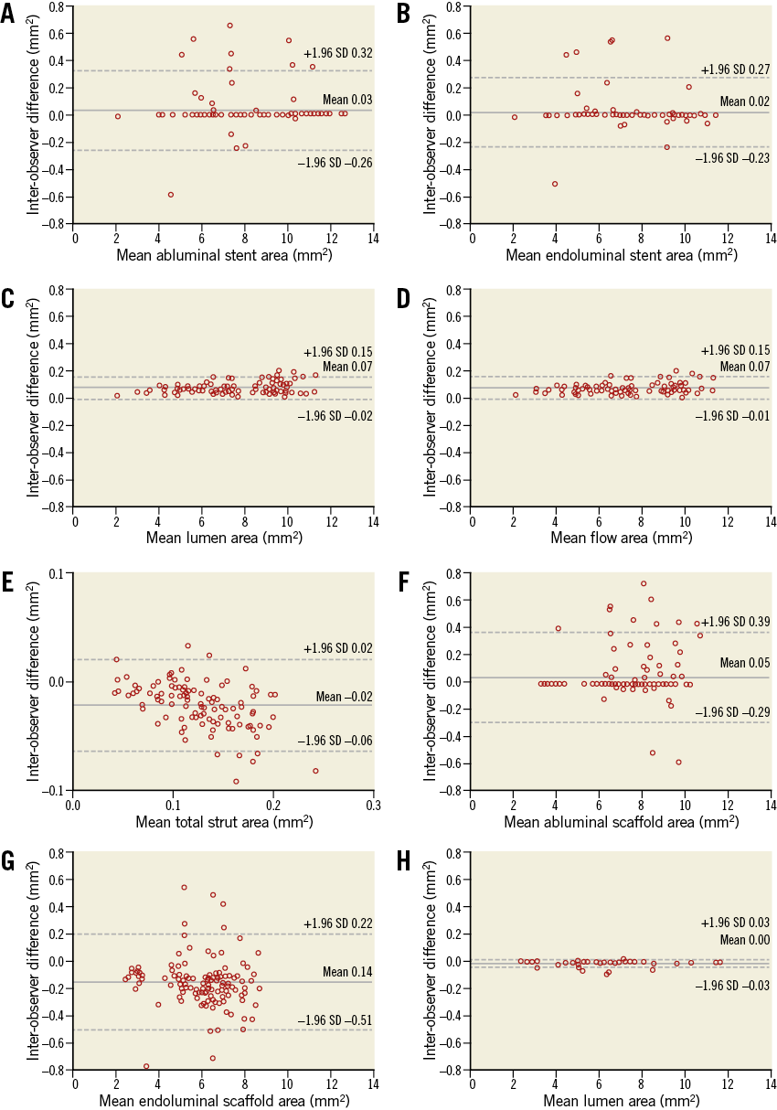
Online Figure 6. Interobserver variability. Bland-Altman analysis was performed for parameters in a metallic stent and a polymeric scaffold. In a metallic stent, mean abluminal stent area (A), mean endoluminal stent area (B), mean lumen area (C), mean flow area (D), and mean total strut area (E) were analysed. In a polymeric scaffold, mean abluminal scaffold area (F), mean endoluminal scaffold area (G), and mean lumen area (H) were analysed.