Abstract
Bioresorbable scaffolds (BRS) in bifurcations have all of the potential advantages of BRS in non-bifurcating lesions and, in addition, the absorption of side branch (SB) ostial struts may at least partially release the branch from “jail”. Polymeric BRS struts may break when post-dilated beyond their safe limits and multiple fractures may lead to adverse clinical events. Bench testing provides insights into the behaviour of different BRS in bifurcations and helps the interventional cardiologist to choose, deliver and post-dilate appropriately. Bench testing of polymeric BRS must be in a water bath at 37ºC as polymer performance is temperature sensitive. Balloon dilatation through the side of a BRS or a durable metallic stent causes distortion corrected by mini-kissing balloon post-dilatation (mini-KBPD) where the SB balloon extends only a short distance into the main branch (MB), limiting the length of MB scaffold exposed to the inflation of two balloons. The safe pressure threshold for SB dilatation of a 3.0 mm Absorb scaffold with a 3.0 mm non-compliant balloon is 10 atm and for mini-KBPD with two 3.0 mm balloons it is 5 atm. Strategies such as culotte, crush and simultaneous kissing scaffolds (SKS) may not be appropriate for the current Absorb scaffold.
Introduction
The potential advantages of bioresorbable scaffolds (BRS) compared to durable stents in non-bifurcating lesions1-3 are likely to apply to bifurcations with the additional advantage that resorption of those struts across the side branch is expected to, at least partially, release the branch from “jail”4,5.
The struts of some polymeric scaffolds break more readily than metallic struts, potentially leading to adverse events6. Different polymeric BRS perform in different ways from each other and from both resorbable and durable metallic DES. Bench testing can provide insights to help guide safe delivery, deployment and post-dilatation. Strategies appropriate for one BRS design may not be appropriate for another. While the magnesium alloy BRS behaves acutely more like a conventional metal DES, a manufacturing challenge is to slow the resorption to oppose negative remodelling2.
Results of the bifurcation bench testing of a small number of Absorb scaffolds (Abbott Vascular, Santa Clara, CA, USA) have been published7,8. We present here some of the results of our BRS bench testing and review some of the limited published data.
Testing and imaging conditions
It is essential that bench testing of polymeric BRS is carried out in liquid at 37ºC9. We use a water bath with close water temperature control as even a few degrees change can alter polymeric performance. We use a number of different mock coronary arteries whose design can follow Murray’s Law10,11. We image deployments with fluoroscopy and photography, and also image deployed scaffolds with microcomputed tomography10. We use environmental scanning electron microscopy to examine scaffolds and coatings.
Bioresorbable scaffold designs
Of six BRS designs for which we have data (Figure 1), five are constructed from polymers and one, the DREAMS (Biotronik, Berlin, Germany), from magnesium alloy. Data are for 3.0 mm examples of scaffolds. The potential cell diameter is important for side branch (SB) access as a small cell may not allow device passage and have a greater risk of strut fracture with balloon inflation. For the Absorb (Abbott Vascular) and DESolve scaffolds (Elixir Medical, Sunnyvale, CA, USA), the cell diameter of approximately 3.0 mm is adequate and it is likely that the FORTITUDE™ (Amaranth Medical, Mountain View, CA, USA) device is similar (Figure 1)9. The DREAMS potential cell size is likely to be larger because there are two not three connectors between hoops. The ReZolve (REVA Medical Inc., San Diego, CA, USA) and ART (Arterial Remodeling Technologies, Noisy le Roi, France) have some cells that are small and suboptimal for bifurcation strategies (Figure 1). While REVA Medical has a new design (Fantom™) that appears to be similar to Absorb, we have not had the opportunity to bench test and do not have specific data yet.
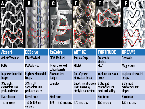
Figure 1. Six different bioresorbable scaffolds. The manufacturers, construction material, design, connector number, antiproliferative drug and strut thickness in microns (including coating thickness) are shown. The red broken lines outline a cell between struts.
While multiple scaffold fractures and protrusion of many struts into the lumen are likely to have adverse consequences6, single strut fracture may have little clinical impact9. When a bioresorbable scaffold is post-dilated with progressively increasing balloon sizes and balloon pressures, the chance of strut fracture increases depending on the construction material and design of the scaffold. This fracture risk is important when using BRS in bifurcations because of the need for safe post-dilatation strategies9. Our testing showed that for a 3.0 mm Absorb scaffold fracture occurs with MB post-dilatation with balloon diameters larger than 3.8 mm (Online Figure 1)9. Strut fractures occur with similar balloon sizes for the ART and ReZolve designs while the DESolve did not fracture at sizes below 4.7 mm12 and DREAMS did not fracture at 5.3 mm.
Side branch dilatation and distortion
Dilatation through the side of stents and scaffolds causes distortion9,13 with malapposition of the scaffold opposite the side branch, narrowing distal to the SB and desirable effects of some clearance of struts from the SB ostium and some protrusion of struts into the SB (Figure 2). There are safe thresholds for mini-KBPD of Absorb scaffolds9 and, when these are exceeded (Figure 2B), strut fracture occurs.
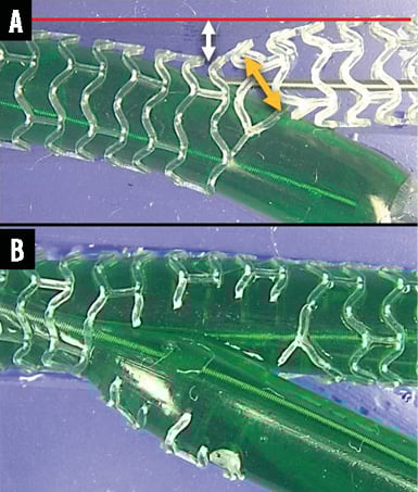
Figure 2. Side branch dilatation for a 3.0 mm Absorb and mini-kissing balloon post-dilatation. The 3.0 mm Absorb scaffold was deployed in a phantom in a water bath at 37ºC. A) The side branch is dilated with a 3.0 mm non-compliant balloon (green) at 10 atm. While side branch dilatation cleared struts from the side branch ostium and protruded some struts into the side branch (A), it also caused distortion with malapposition of struts opposite to the side branch (white double-headed arrow) and narrowing of the scaffold distal to the side branch (yellow double-headed arrow) but no strut fractures at this pressure. B) The mini-kissing balloon post-dilatation with two 3.0 mm non-compliant balloons at 10 atm exceeded the safe threshold9, extensively fracturing struts.
For a 3.0 mm Absorb scaffold, and SB dilatation with a 3.0 mm NC balloon there is a safe threshold9 of 10 atm at or below which strut fracture does not occur (Figure 3A). With mini-KBPD, the safe threshold for a 3.0 mm Absorb scaffold with two 3.0 mm NC balloons is 5 atm9 at or below which fracture does not occur (Figure 3B).
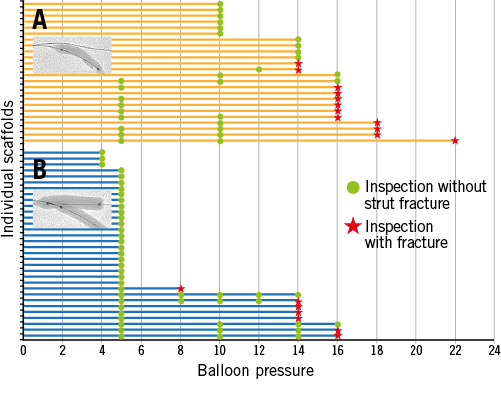
Figure 3. Side branch dilatation and mini-kissing post-dilatation. A) Individual 3.0 mm scaffolds after 3.0 mm side branch balloon dilatation and increasing pressure. B) Similar scaffolds with mini-KBPD with two 3.0 mm balloons and increasing pressure. The green points represent inspection with no fracture and the red stars represent fractured strut(s). (Modified from EuroIntervention9 with permission from Europa Digital & Publishing)
Post-dilatation strategies
Post-dilatation strategies are described in Figure 4.
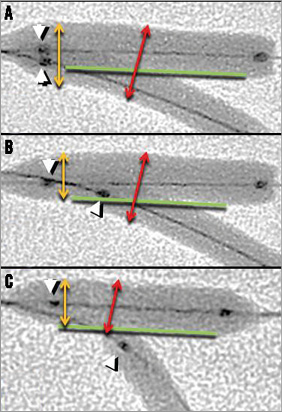
Figure 4. Post-dilatation strategies. With conventional kissing balloon post-dilatation (A), the main branch balloon and the proximal portion of the side branch balloon lie in the main branch with proximal markers aligned (white arrowheads). With mini-kissing balloon post-dilatation (B), a short length of side branch balloon lies in the main branch but does not extend back to the proximal portion of the scaffold. With “snuggle” balloons (C), the side branch balloon lies entirely within the side branch. The double-headed yellow arrows indicate that conventional kissing post-dilatation exposes the proximal scaffold to two balloons (A) whereas with mini-kissing balloon post-dilatation (B) and “snuggle” balloons (C) the proximal scaffold is exposed to only one balloon. Balloon diameters in the bifurcation (red double-headed arrows) are similar for the kissing strategies (A & B) but less for “snuggle” (C).
General policy for deploying an Absorb scaffold in a bifurcation
When deploying an Absorb in the bifurcation MB in a provisional side branch strategy9, a guidewire (0.014”) is passed to each branch. In contrast to the European Bifurcation Club recommendations for metallic stents14,15, we recommend sizing the scaffold to the proximal main branch to allow safer proximal post-dilatation. Following proximal optimisation14, if there is need for side branch dilatation, we rewire the side branch through the side of the scaffold then dilate through the side of the scaffold. Distortion is corrected with mini-KBPD. Balloon pressures used are below the safe thresholds9 (Figure 3). If necessary, we would stent or scaffold the side branch using a “T” strategy.
Culotte scaffold deployment
The two-scaffold culotte bifurcation strategy with a 3.5 mm MB scaffold and a 3.0 mm SB scaffold is shown in Figure 5 and in Moving image 1. A 3.5 mm balloon passed from the proximal MB through the side of the SB scaffold was inflated to 12 atm. After this, for mini-KBPD this 3.5 mm MB balloon and a 3.0 mm balloon in the SB were inflated simultaneously to 7 atm. One of these post-dilatation manoeuvres caused a single connector fracture in the SB scaffold. This type of fracture is probably of no clinical significance as connectors do not provide radial support and function only to hold hoops together. In addition, this fractured connector did not protrude into the lumen. We have performed culotte scaffold deployment in only a small number of scaffolds.
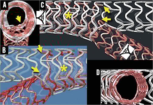
Figure 5. Culotte bifurcation scaffolding with a 3.5 mm Absorb in the main branch (white scaffold) and a 3.0 mm scaffold from the main to side branch (red scaffold). Yellow arrows in panels A, B and C indicate a connector fracture in the side branch scaffold. The asterisk indicates two layers of struts. Some side branch struts protrude into the main branch in A. There is no side branch obstruction (D).
Mini-crush scaffold bifurcation deployment
The two-scaffold mini-crush bifurcation strategy16,17 is demonstrated in Online Figure 2 and Moving image 2.
Simultaneous kissing scaffold deployment
The two Absorb scaffold strategy, called simultaneous kissing scaffolds (SKS)18, is shown in Online Figure 3 and Moving image 3. We have performed only a small number of these deployments.
Scaffold coating integrity after withdrawal of a wire trapped between scaffold and phantom wall
Withdrawal of a wire trapped between an Absorb and the phantom causes a line of damage to the polymeric coating (Online Figure 4). However, the area of scaffold bare of coating is relatively small and much smaller than the gaps between struts, so is unlikely to have clinical importance.
Summary
The interventionalist needs to understand the different BRS performance characteristics in order to select appropriate coronary lesions for BRS, and to deliver, deploy and post-dilate BRS appropriately and safely. Because polymeric BRS struts may break more readily than those of metallic stents it is essential that the interventionalist understands safe balloon size and pressure post-dilatation limits. It is likely that the “T” strategy with a metallic drug-eluting stent is the best strategy if, after deployment of an MB scaffold, the SB needs treatment. The culotte, crush and SKS strategies have important disadvantages, including technical difficulty, multiple strut layers and the potential for strut fracture. The withdrawal of a trapped wire during a provisional SB strategy causes a limited amount of polymer coating damage.
Funding
The Auckland Heart Group Charitable Trust.
Conflict of interest statement
J. Ormiston is an advisory board member for Abbott Vascular and Boston Scientific and has received minor honoraria from them. O. Darremont is an advisory board member for Abbott Vascular. The other authors have no conflicts of interest to declare.
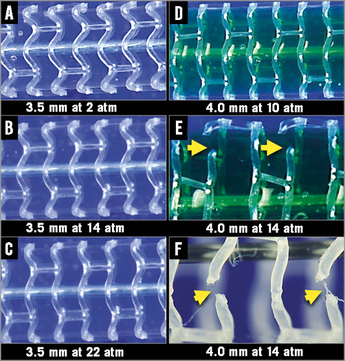
Online Figure 1. Absorb scaffold post-dilatation and fracture. A 3.0 mm Absorb scaffold post-dilated with increasing non-compliant balloon diameters and increasing pressure caused straightening and stretching of sinusoidal hoops (A-D). In this individual scaffold strut fracture occurred with a 4.0 mm balloon inflated to 14 atm (E & F).
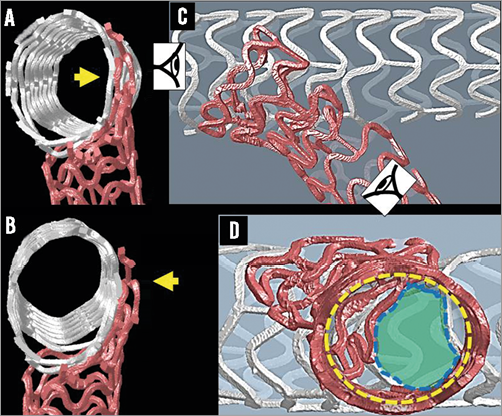
Online Figure 2. Mini-crush Absorb scaffold deployment. Deployment of the main branch 3.5 mm scaffold (white) has crushed a short length of 3.0 mm side branch scaffold (red) (C,D). Yellow arrows indicate the three layers of crushed strut each 157 µm thick (A,B). Main branch scaffold post-dilatation with a 3.5 mm NC balloon was followed sequentially by a side branch post-dilatation with a 3.0 mm NC balloon each at 16 atm then kissing post-dilatation (same balloons) at 5 atm. The side branch struts (red) have not been fully cleared from the side branch ostium (D). Broken yellow line: side branch ostium; broken blue line: lumen free of struts.
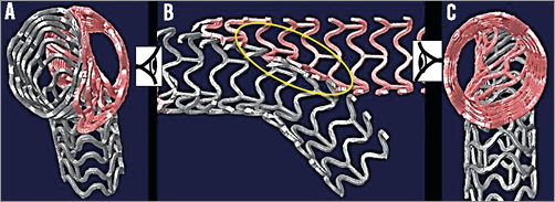
Online Figure 3. Simultaneous kissing scaffolds (SKS). While the scaffolds can be deployed simultaneously through a large guide, the same result can be achieved by sequential deployment then kissing post-dilatation. The lumens are asymmetrical (A & C). Two layers of struts partition the main branch (B, yellow oval).
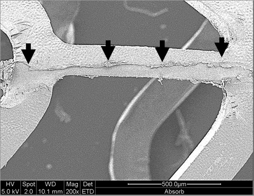
Online Figure 4. Environmental scanning electron microscope images of an Absorb scaffold. Damage to the Absorb polymer coating (black arrows) was caused by withdrawal of a 0.014” BALANCE MIDDLEWEIGHT guidewire (Abbott Vascular) trapped between the scaffold and phantom.
Online data supplement
Moving image 1. Culotte bifurcation scaffolding with a 3.5 mm Absorb in the main branch (white scaffold) and a 3.0 mm scaffold from the main to side branch (red scaffold).
Moving image 2. Mini-crush Absorb scaffold deployment. The deployment of the main branch 3.5 mm scaffold (white) has crushed a short length of 3.0 mm side branch scaffold (red). There are three layers of crushed strut each 157 µm thick. Main branch scaffold post-dilatation with a 3.5 mm NC balloon was followed sequentially by a side branch post-dilatation with a 3.0 mm NC balloon each at 16 atm then kissing post-dilatation (same balloons) at 5 atm. The side branch struts (red) have not been fully cleared from the side branch ostium.
Moving image 3. Simultaneous kissing scaffolds (SKS). While the scaffolds can be deployed simultaneously through a large guide, the same result can be achieved by sequential deployment then kissing post-dilatation. The lumens are asymmetrical and two layers of struts partition the main branch.
Supplementary data
To read the full content of this article, please download the PDF.
Moving image 1. Culotte bifurcation scaffolding with a 3.5 mm Absorb in the main branch (white scaffold) and a 3.0 mm scaffold from the main to side branch (red scaffold).
Moving image 2. Mini-crush Absorb scaffold deployment. The deployment of the main branch 3.5 mm scaffold (white) has crushed a short length of 3.0 mm side branch scaffold (red). There are three layers of crushed strut each 157 µm thick. Main branch scaffold post-dilatation with a 3.5 mm NC balloon was followed sequentially by a side branch post-dilatation with a 3.0 mm NC balloon each at 16 atm then kissing post-dilatation (same balloons) at 5 atm. The side branch struts (red) have not been fully cleared from the side branch ostium.
Moving image 3. Simultaneous kissing scaffolds (SKS). While the scaffolds can be deployed simultaneously through a large guide, the same result can be achieved by sequential deployment then kissing post-dilatation. The lumens are asymmetrical and two layers of struts partition the main branch.