Abstract
Stepwise layered provisional stenting (PS) is the most commonly used strategy to treat coronary bifurcation lesions (CBL). The term “stepwise layered” emphasises the versatility of this approach that allows the adjustment of the procedure plan according to the CBL complexity, starting with stent implantation in one branch and implantation of a second stent in the other branch only when required. A series of refinements have been implemented over the years to facilitate the achievement of predictable procedural results using this approach. However, despite its simplicity and versatility, operators using this technique require full knowledge of the pitfalls of each procedural step. Part I of this 16th European Bifurcation Club consensus paper provides a detailed step-by-step overview of the pitfalls and technical troubleshooting during the implantation of the first stent using the PS strategy for the treatment of CBL.
Introduction
The stepwise layered provisional stenting (PS) strategy is recommended for the vast majority of patients with non-true non-left main (non-LM) coronary bifurcation lesions (CBL) or true non-LM CBL with a side branch (SB) lesion length <10 mm12345. The PS approach, which belongs to the “A” family of the "Main, Across, Distal, Side" (MADS-2) classification (main Across side first=standard PS; Across distal main first=inverted PS)1, is the most commonly used strategy to treat CBL with the intention to use a single stent. Although there have been mixed results regarding the long-term efficacy and safety between 1-stent versus 2-stent approaches in all-cause mortality, the strategy to treat true CBL (Medina classification 1,0,1; 1,1,1; 0,1,1) with the implantation of a single stent is supported by the results of a meta-analysis of randomised trials. This demonstrated that a 1-stent approach is associated with a reduction in all-cause mortality at follow-up (>1 year) compared with the upfront use of more complex 2-stent bifurcation strategies6. Furthermore, the PS approach also remains the first choice for the majority of patients with true left main CBL with an SB lesion length <10 mm, where equivalent outcomes are achieved with the PS approach versus a more complex systematic (upfront) 2-stent approach7. The PS strategy is a treatment philosophy, rather than a technique4, that meets the main objective of CBL treatment of reconstructing the bifurcation anatomy with a single stent, generally implanted from the proximal to the distal segment of the main vessel (MV) across the ostium of the SB and followed by systematic proximal optimisation technique (POT)2. Consideration of the “operative” MV axis is mandatory with the PS approach, as in some instances it is more appropriate to stent from the proximal main vessel (pMV) to the SB (inverted PS), also defined as “inverted A” according to the MADS-2 treatment classification1. When the inverted PS is the operator’s intention-to-treat strategy, an “operative” nomenclature should be adopted: redefining the stented SB segment as “distal main vessel” (dMV), while the original (“anatomical”) dMV is redefined as the “assigned side branch” (aSB). The fundamental advantage of the PS approach is that treatment of the SB/aSB remains an “open” option throughout the procedure8 and develops “stepwise”, with the aim of performing an optimal treatment of the bifurcation with a single stent whenever possible, and performing stenting of the SB/aSB when necessary9 using the T, T and small protrusion (TAP), or culotte implantation techniques23810. Despite this philosophical approach, it is acknowledged that an intentional (upfront) 2-stent approach9 may be required in true, complex CBL with a long (>10 mm) diseased SB/aSB511. The benefits of an upfront 2-stent technique for patients with complex CBL with a long (>10 mm) diseased SB/aSB were evaluated in the multicentre, randomised DEFINITION II trial12 where a systematic 2-stent approach was associated with a significant improvement in clinical outcomes compared with the PS approach. However, we reiterate that the simpler 1-stent approach is also appropriate for the treatment of true CBL with a shorter SB/aSB lesion length (<10 mm), as demonstrated by the results of the European Bifurcation Club (EBC) MAIN trial7.
In part I of this consensus paper, we describe the PS approach (standard or inverted12) followed by a detailed and systematic description of potential pitfalls encountered during implantation of the first stent, with consideration of their mechanisms, strategies of prevention and provision of step-by-step technical troubleshooting recommendations (Central illustration). Considering the pitfalls of the PS technique, we recommend a 3-stage approach (ABC) to deployment of the first stent: stage A refers to the wiring of the MV and SB, stage B to MV and SB preparation and stage C to stent implantation and optimisation.
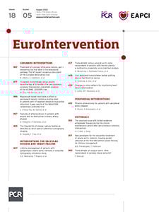
Central illustration. Step-by-step pitfalls, technical troubleshooting and pitfall prevention during the implantation of the first stent using the provisional strategy for the treatment of coronary bifurcation lesions. An example pitfall is shown in the left panels. The red image borders denote where the pitfall occurred. The blue image border denotes the step commonly performed not suspecting the previous pitfall. The panel on the right with the violet border denotes the
corrective step that arises from the pitfall. The panel on the right with the green border denotes how to prevent the pitfall. pMV: proximal main vessel; POT: proximal optimisation technique; SB/aSB: side branch/assigned side branch
The primary objective of part I of this consensus document is to aid the interventionalist in anticipating the nuances and potential complications associated with the PS strategy. Ideally, this enhanced awareness will facilitate adherence to the EBC recommendation of “keeping it simple and safe”, despite the acknowledged iterative enhancements to the PS strategy that have increased the technical/procedural considerations.
The ABC approach to treatment of CBL using the PS strategy
Stage A – MV and SB wiring
The first stage for the treatment of CBL with any stenting strategy is to wire both the MV and the SB. The EBC recommends the systematic use of the “jailing wire” technique34, which involves maintaining the SB wire during MV stent implantation. A “jailed wire” may help to keep the SB open and, in case of occlusion, it can be used to facilitate SB reopening through the passage of a low-profile balloon and/or a microcatheter behind the MV stent, to regain SB flow13. Interestingly, in the French multicentre TULIPE study, the absence of a “jailed wire” was associated with a lower angiographic success of the procedure and a higher rate of reintervention during follow-up14. In contrast, the COBIS (Coronary Bifurcation Stenting) III registry observed that wire jailing at the SB was associated with a lower rate of final SB occlusion following MV stenting, although the benefit was limited to patients with severe stenoses at the SB or MV15. This stage is often the most difficult and time consuming in the procedure. Wiring is often repeated (“rewiring”) during the procedure. Wiring and rewiring in the most complex cases are challenging and require specific operator experience or techniques to avoid the following pitfalls.
Pitfalls
Difficult SB access
This is the result of (1) MV tortuosity and/or an angulated SB, (2) the presence of a severe bifurcation stenosis or of a very eccentric plaque, and (3) the presence of severe CBL calcification.
Troubleshooting
(1) A difficult SB access as a result of MV tortuosity and/or angulated SB can be overcome in the majority of CBL using the antegrade or the pull-back technique, using an appropriate guidewire (workhorse, stiff or with hydrophilic polymer coating) with an appropriately shaped tip curvature. Burzotta et al16 described 4 common types of guidewire tip shape for CBL: (a) single bend with short tip (2-3 mm); (b) single bend with long tip (4-6 mm); (c) single wide bend; (d) double bend shape. For example, when the problem is a wide angle between the proximal MV and the SB axes (a pattern which is typically encountered in the circumflex takeoff from the LM), a useful solution is to shape the tip with a wide smooth bend or with a double bend (the second solution being more practical when the SB/aSB lesion is tighter).
(2) The challenge of a severe bifurcation stenosis can be solved by moving to a dedicated, tapered tip hydrophilic wire (e.g., Fielder XT [Asahi Intecc]).
(3) Severely calcified CBL can be effectively treated by calcium modification techniques17 (i.e., MV rotational or laser atherectomy) to restore an adequate lumen, thus increasing SB lesion “crossability” during the subsequent rewiring attempt.
For more complex CBL, “advanced” wiring and rewiring technique are required to solve the challenge of difficult SB access: (a) the long U-shape “reverse wire” technique16, which is a more extreme variation of the pull-back techniques, and is also called the “hairpin” wire technique. The hairpin is advanced past the branch and is then withdrawn, unfolding and entering the branch18; (b) the use of dual lumen microcatheters or single lumen microcatheters with a deflectable or fixed tip (Venture catheter [Teleflex] and SuperCross [Teleflex]); or (c) proximal MV balloon predilatation including the POT balloon. Many operators consider this solution as a “last resort” strategy to wire the SB/aSB. Indeed, this technique is basically not advisable in the vast majority of CBL as it may cause plaque and carina shift, risking SB/aSB occlusion.
“Wire wrap” (twisting of the wires)
This is a common problem and results in difficulty tracking balloons/stents across the bifurcation, whether attempting to negotiate a device into the MV or SB.
Troubleshooting
Prompt recognition of wire wrap is important to avoid prolongation of the procedure; suspicion of this should arise anytime unanticipated difficulty in advancing balloons and stents over a wire is encountered. Retrograde movement of the non-instrumented wire, with forward movement of a device, can be a useful, indirect sign of wire wrap. In such cases, forceful device advancement might cause wire entrapment, wire kinking or loss of wire position. Instead, wire wrap can be easily resolved by withdrawal of one of the wires into the guiding catheter and readvancement, without excessive torque. Wire retrieval is safe in the absence of kinking, entrapment or structural damage of the wire. In addition, in selecting which wire to retrieve, the operator should opt to leave in place the wire located in the branch that was most difficult to wire and/or in the branch with the greatest risk of occlusion (complex plaque morphology, predilation-induced dissections, etc.). Moreover, in selected cases with complex anatomy, rewiring after wire retrieval might be facilitated by the use of a dual lumen microcatheter delivered over the wire left in place.
Prevention
The risk of wire wrap should be systematically prevented. Wiring the most difficult branch first decreases the risk of wire interaction. Over-rotation of the second wire during advancement, particularly in a single direction, increases the likelihood of wire wrap with the first inserted wire. Furthermore, wire management within the operative field is important, with minimisation of wire manipulation. We recommend avoidance of 2nd wire over-rotation, through use of a torquing device and <180° rotation in 1 direction, and separation of externalised wires through use of drapes/gauze. Finally, when a difficult SB access is anticipated, the use of a dual lumen microcatheter has the potential to facilitate multiple guidewire attempts while minimising the risk of wire wrap. However, it is important to acknowledge that the use of a dual lumen catheter or microcatheter increases the tip load of any exiting wire, thereby increasing the risk of vessel trauma/dissection.
Distal perforation or dissection
This is the result of advancing the wires too distally. Distal coronary perforation can cause early or late tamponade.
Troubleshooting
Distal coronary perforation (guidewire exit perforation, which is sometimes referred to as type V perforation19) may occur during any phase of the procedure, and its prompt recognition is critical to avoid/minimise serious consequences. Where distal coronary perforation is suspected, a prolonged angiographic acquisition over the entire coronary tree is recommended. In addition, multiple acquisitions in different projections and their careful revision are advised where suspicion of distal perforation exists. The first treatment step of guidewire exit perforation is balloon inflation proximal to the perforation site. Occasionally, this is sufficient to seal the leak, but if contrast extravasation persists, definitive embolisation intervention is required with fat, coil, cut balloon, thrombin or autologous clotted blood19. In case of severe SB perforation, a strategy that should be considered in selected cases (particularly in smaller SB) when other approaches fail or are not feasible is the occlusion of the ostium of the SB via implantation of a covered stent in the MV20.
Prevention
The use of workhorse guidewires and vigilance regarding guidewire tip position minimises the risk of distal vessel perforation (as well as of distal branch dissections).
Stage B – MV and SB preparation
The second stage for the treatment of CBL is to adequately prepare the MV and the SB in order to facilitate stent delivery and optimal stent expansion. Failure to adequately prepare the SB, when required (i.e., severely stenotic [>90%], calcified, angulated lesion), must be avoided.
Pitfalls
Failure to advance a balloon or stent into the MV or the SB of a CBL
This tends to reflect suboptimal lesion preparation, often encountered in a severely calcified CBL, even after multiple dilations with non-compliant (NC) balloons and may increase the risk of stent underexpansion or stent loss. Optimal lesion preparation facilitates appropriate sizing and radially concentric expansion of the CBL stents. An optimal lesion preparation before stenting is defined as that required to achieve an optimal angiographic result after stenting (<10% stenosis) or an optimal final lumen stent area as assessed by intracoronary imaging based on predefined optimisation criteria (e.g., predefined intravascular ultrasound [IVUS]-guided optimisation criteria for distal LM lesions include a complete stent apposition and a minimum stent area >90% of the reference segment area21).
Troubleshooting
An algorithmic approach to overcome failure to advance a balloon or stent into the MV or the SB of a CBL has recently been proposed18 which includes the following steps: 1) additional SB dilation using lower profile balloons (≤1.5 mm); 2) pass a microcatheter (MC) and then reattempt ballooning; 3) ensure adequate guide support (considering guide extension and anchor balloon); 4) if possible (ideally via an MC), exchange wire for a Wiggle wire (Abbott); 5) calcium modification techniques17 (rotational, laser and orbital atherectomy, scoring and cutting balloons, coronary lithoplasty) if appropriate, that should also be considered early or upfront for MV, heavily calcified vessels and calcified distal LM bifurcations.
Prevention
Care must be taken to identify the presence of significant calcification, especially as it is well known that angiography underappreciates the burden of calcific disease22. Balloon expansion should be visualised in 2 orthogonal projections, and where there is uncertainty or ambiguity there should be a low threshold for intracoronary imaging. Criteria for the prediction of stent underexpansion, secondary to high burden calcification, have been extensively reported, and the use of adjunctive calcium modification techniques (rotational and orbital atherectomy, scoring and cutting balloons, coronary lithoplasty)23 should be considered where, using optical coherence tomography (OCT), a calcium arc exceeds 180 degrees, with a thickness >0.5 mm and a longitudinal extent >5 mm24. Both MV and SB/aSB lesion preparation is recommended in complex true CBL (SB/aSB stenosis >90%, long SB/aSB lesion length >10 mm, severe calcification, bifurcation angle >75 degrees). In contrast, when dealing with a CBL that does meet the DEFINITION criteria for complex lesions12 we recommend predilating only the MV toward the branch receiving the first stent, in order to facilitate the rewiring of the SB/aSB through a distal strut, close to the carina. This should ensure adequate stent expansion while minimising the risk of ostial dissection of the SB/aSB and subsequent difficulty in rewiring.
Stage C – Stent implantation and optimisation
The third stage for the treatment of CBL is stent implantation and optimisation undertaken in a series of steps.
Provisional stent implantation in 5 steps
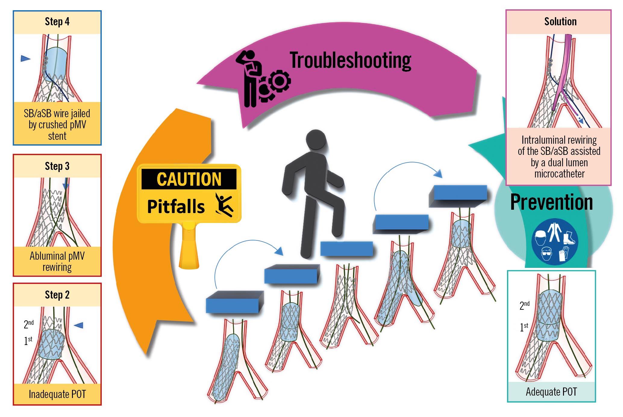
The 5 recommended steps to perform the PS strategy, previously reported in technical consensus papers1234, are described in detail below and illustrated in Figure 1 (adapted from Lassen et al4).
Step 1: MV stenting across the SB/aSB takeoff (also called “crossover stenting”), with a drug-eluting stent (DES) sized 1:1 according to dMV diameter, leaving in place the SB/aSB wire (jailing wire technique), with a DES length (even in the absence of a relevant disease) allowing for pMV coverage of a segment equal to or longer than the shortest available POT balloon (6-8 mm).
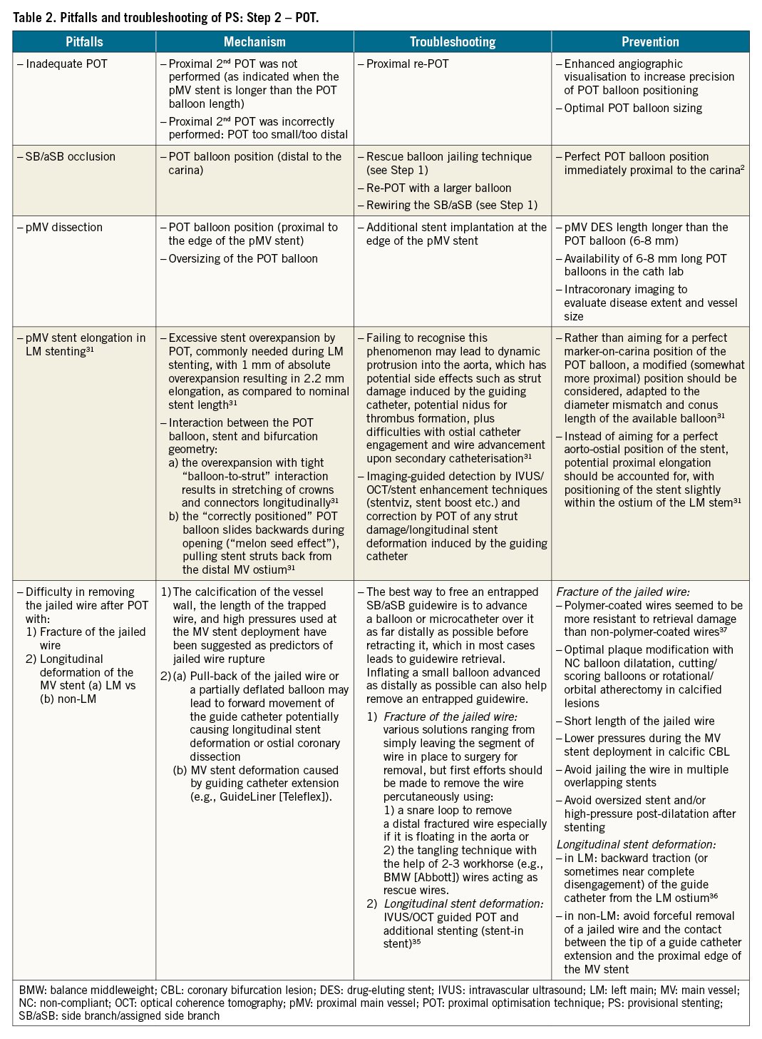
Step 2: Systematic post-dilation (1st POT) with a balloon sized 1:1 to the pMV with meticulous attention paid to POT balloon position, focusing on accurate placement of the distal shoulder immediately proximal to the carina, as bench tests have demonstrated this provides optimal POT results25. In the case of a long, stented pMV segment, a 2nd POT balloon inflation is needed to appropriately post-dilate the entire pMV stent segment. The initial 2 steps are regarded as mandatory. With an optimal result in the MV and acceptable SB/aSB patency, the procedure can end at this step (Figure 1, procedure end @ Step 2).
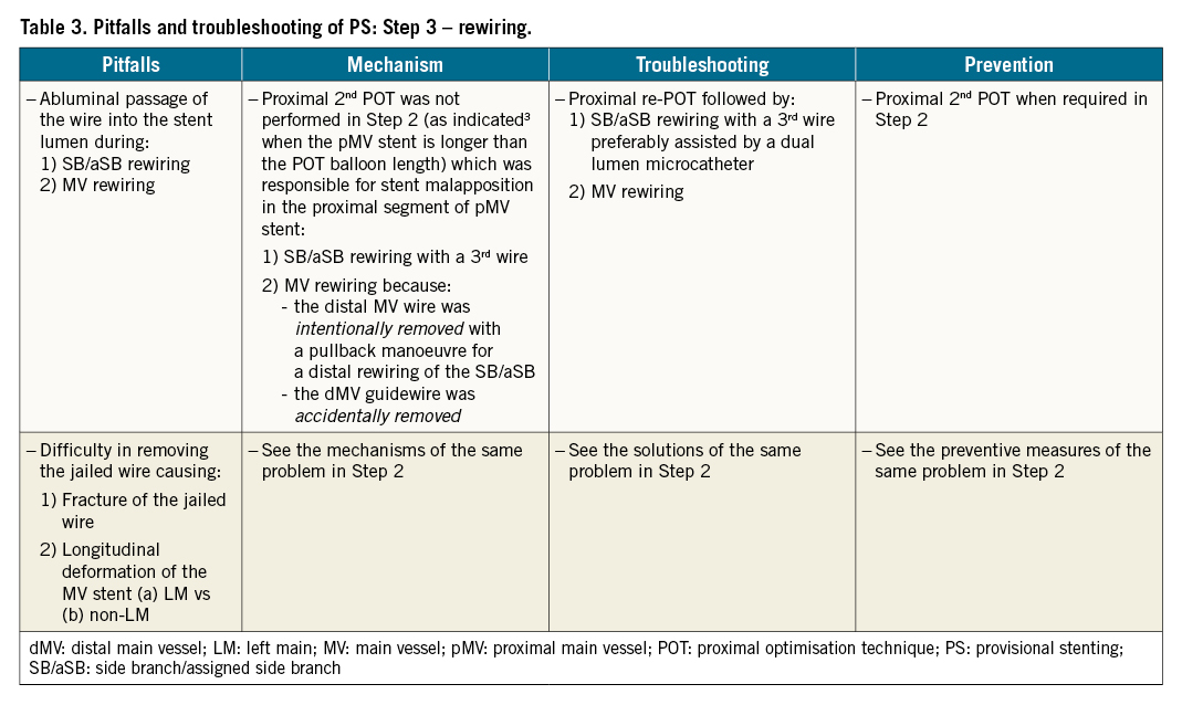
However, when a relevant SB/aSB is compromised and merits further intervention, the next step consists of opening the MV stent toward the SB/aSB. This is done by rewiring the distal SB/aSB (Step 3), according to the pullback technique, using a 3rd wire (Figure 1, Step 3A) or pulling back the wire from the dMV (Figure 1, Step 3B), followed by SB/aSB dilation (Figure 1, Step 4) using kissing balloon inflation (KBI) with an MV balloon sized 1:1 according to the dMV and an SB/aSB balloon (preferably an NC balloon to avoid any SB dissection) sized 1:1 according to the SB/aSB diameter. KBI technique alone or KBI followed by repeated POT are the usual initial approaches. Alternatively, the operator can perform SB/aSB dilation (preferably with an NC balloon to avoid any SB/aSB dissection) followed by repeated POT. To date, clinical data26 do not support the routine adoption of Steps 3 and 4 (broken-line arrow in Figure 1). With an optimal result in the MV and acceptable SB/aSB patency, the procedure can end at Step 4 (Figure 1, procedure end @ Step 4).
Where an SB/aSB result after ballooning is not acceptable (i.e., the presence of significant SB/aSB flow limitation or poor angiographic results in the SB/aSB4), provisional SB/aSB stenting is required (Step 5), as described in part II of this consensus document9.
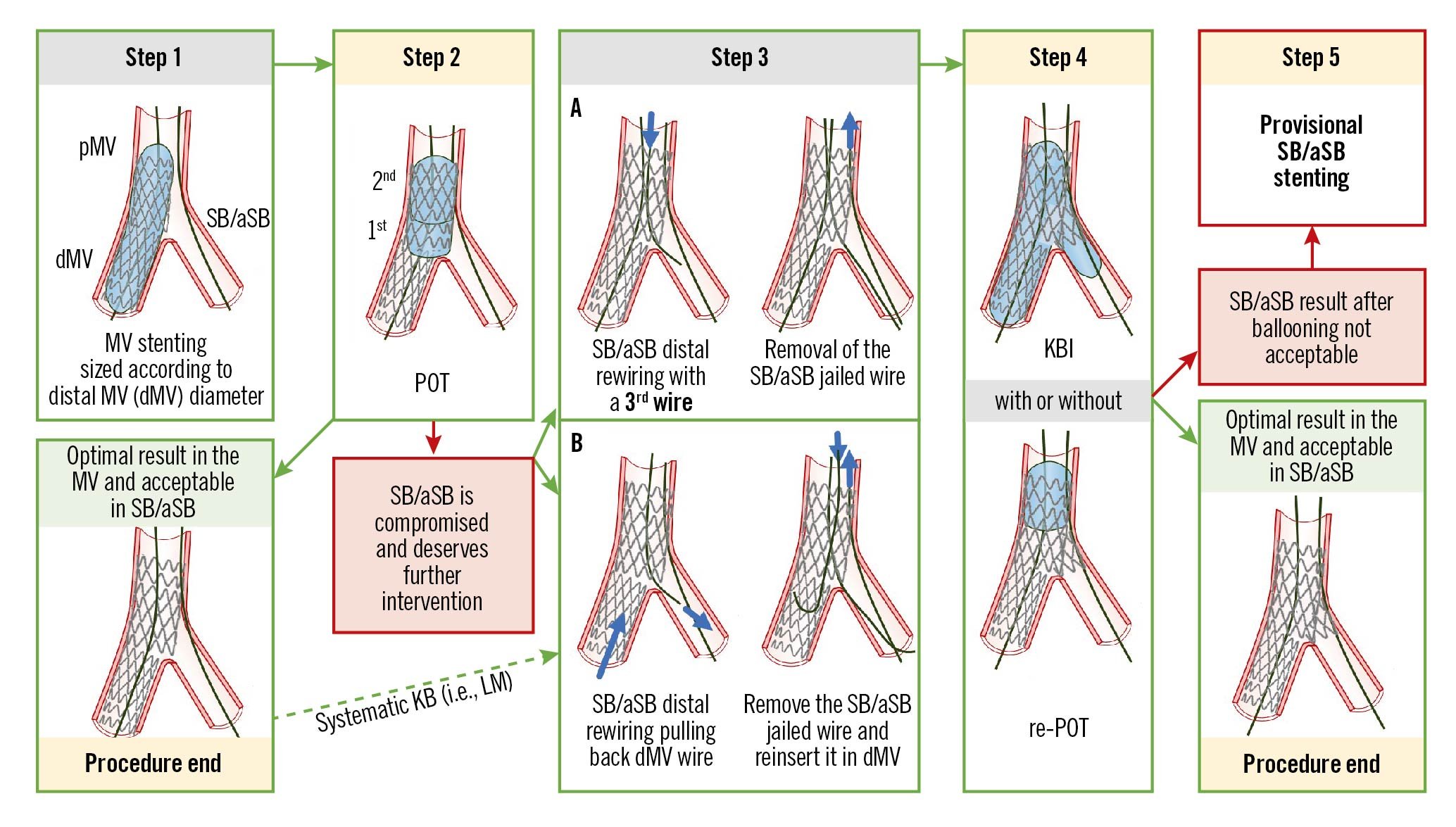
Figure 1. The recommended 5 essential steps for the PS technique, previously reported in technical consensus papers14 (adapted from Lassen et al4). See main text for detailed description. dMV: distal main vessel; LM: left main; KBI: kissing balloon inflation; pMV: proximal main vessel; POT: proximal optimisation technique; PS: provisional stenting; SB/aSB: side branch/assigned side branch
The pitfalls, mechanisms, troubleshooting and prevention of each of the first 4 recommended steps are described in Table 1-Table 4, respectively.
In the following section, we will focus upon pitfalls relating to Step 4 that can be difficult to recognise by angiography alone, and may only be appreciated through subsequent procedural complications and/or the use of X-ray stent enhancement/intracoronary imaging modalities.
Pitfalls
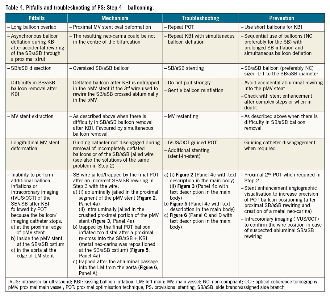
If, in Step 4, after the initial KBI followed by re-POT, additional balloon/stent treatments or intracoronary imaging (IVUS/OCT) of the SB/aSB are required, the operator is occasionally unable to deliver the balloon/stent/imaging catheter because the access is unexpectedly obstructed. The catheter can stop at different locations: 1) at the proximal edge of the pMV stent; 2) inside the pMV stent at the SB/aSB ostium; 3) in the aorta at the edge of an ostial LM stent. This can be caused by pitfalls of prior steps.
1) The catheter stops at the proximal edge of the MV stent
This is caused by jailing the wire used to rewire the SB/aSB. The wire can be jailed: (A) abluminally in the proximal segment of the pMV stent (Figure 2, Panel 4a), or (B) intraluminally in the (inadvertently crushed) proximal segment of the pMV stent (Figure 3, Panel 4a). In both cases, this was made possible by a malapposition in the proximal segment of the pMV stent (Figure 2, Figure 3, Step 3a-Step 3b), resulting from an inadequate POT (Figure 2, Figure 3, Step 2, arrowhead) as defined in Table 2. An additional mechanism to consider is “candy-wrapping” of the proximal edge that occurs after marked stent overexpansion, e.g., a 3.5 mm platform taken to 5.0-5.5 mm. The mechanism and troubleshooting are different for each scenario described as (A) and (B).
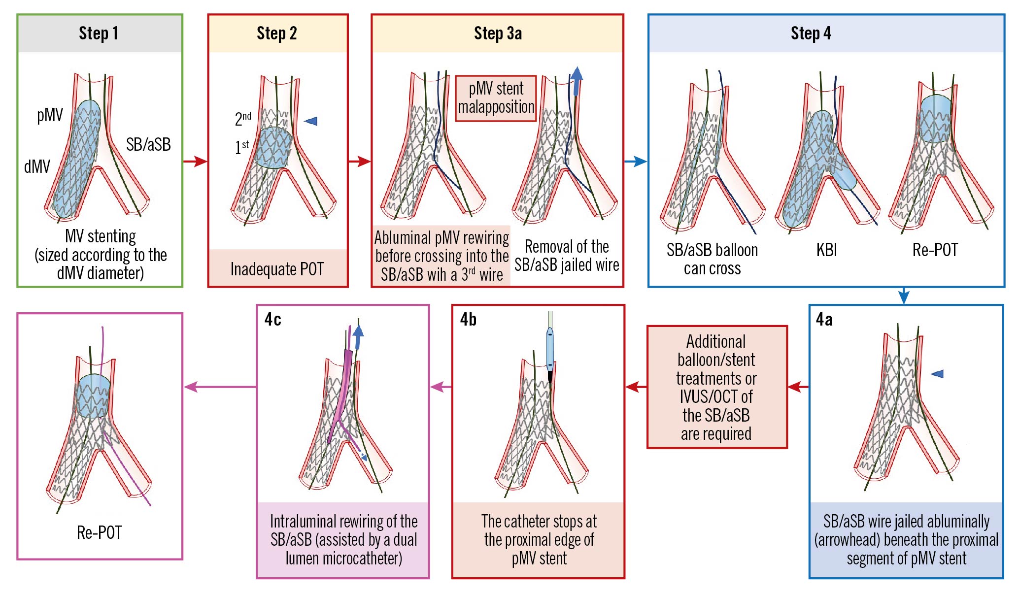
Figure 2. The SB/aSB wire is jailed abluminally beneath the proximal segment of pMV stent. See main text for detailed description. The green image border denotes the optimal step. The red arrows and image borders denote where potential mistakes may occur (pitfalls). The violet arrows and image borders denote the corrective steps that arise from the pitfalls. The light blue arrows and image borders denote the steps commonly performed not suspecting the previous pitfalls. dMV: distal main vessel; IVUS: intravascular ultrasound; KBI: kissing balloon inflation; OCT: optical coherence tomography; pMV: proximal main vessel; POT: proximal optimisation technique; SB/aSB: side branch/assigned side branch
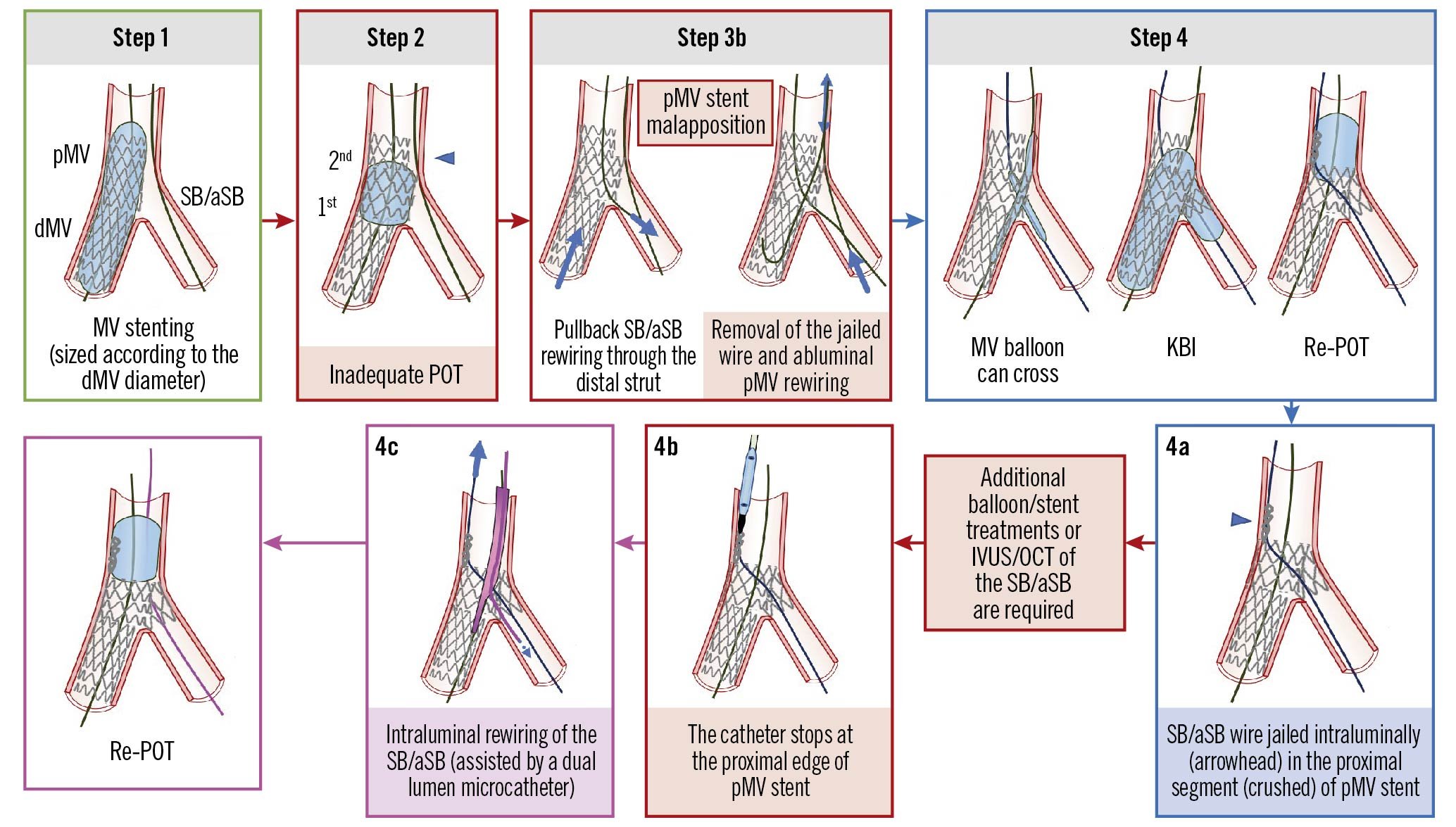
Figure 3. The SB/aSB wire is jailed intraluminally in the (crushed) proximal segment of the pMV stent. See main text for detailed description. The green image border denotes the optimal step. The red arrows and image borders denote where potential mistakes may occur (pitfalls). The violet arrows and image borders denote the corrective steps that arise from the pitfalls. The light blue arrows and image borders denote the steps commonly performed not suspecting the previous pitfalls. dMV: distal main vessel; IVUS: intravascular ultrasound; KBI: kissing balloon inflation; OCT: optical coherence tomography; pMV: proximal main vessel; POT: proximal optimisation technique; SB/aSB: side branch/assigned side branch
(A) The SB/aSB wire is jailed abluminally beneath the proximal segment of the pMV stent (Figure 2, Panel 4a, arrowhead)
Mechanism
In Step 3, rewiring of the SB/aSB is frequently performed using a 3rd wire. In the presence of malapposition in the proximal segment of the pMV stent due to an inadequate POT (Figure 2, Step 2, arrowhead), the 3rd wire can pass in the space between the MV wall and the proximal malapposed segment of the pMV stent (abluminal pMV rewiring, as shown in Figure 2, Step 3a, left schematic image) before crossing into the SB/aSB. Commonly, the operator cannot recognise this abluminal pMV rewiring by simple angiography, but must rely upon tactile feedback from wire manipulation through the struts or by the use of X-ray stent enhancement and/or intracoronary imaging (IVUS/OCT). The EBC recognises intracoronary imaging as the gold standard for confirming wire position, but where not available or adequately reimbursed, X-ray stent enhancement (now available in almost all new angiography systems) offers a potential solution to help identify an abluminal pMV rewire position at no additional cost, minimal impact on procedural duration and only a slight increase in radiation dose for patients and operators27. It is possible, following inadvertent abluminal pMV rewiring, to accomplish KBI particularly when a new SB/aSB balloon is used that can follow the abluminal track of the wire with minimal friction (Figure 2, Step 4, left schematic image), indistinguishable from the friction that occurs during a normal (non-abluminal) crossing of an SB/aSB balloon. It should be noted that an additional potential pitfall can occur: after KBI (Figure 2, Step 4, centre image), a deflated NC/stiff/large SB/aSB balloon can remain entrapped in the pMV stent and be difficult to remove. If KBI is followed, as recommended, by proximal re-POT (Figure 2, Step 4, right image) the SB/aSB wire will be jailed abluminally beneath the very proximal segment of the pMV stent (Figure 2, Panel 4a, arrowhead) obstructing the access into the pMV by any subsequent device (Figure 2, Panel 4b).
Troubleshooting
The solution to this problem is the intraluminal rewiring of the SB/aSB, preferably assisted by the use of a dual lumen microcatheter advanced on the MV wire (Figure 2, Panel 4c), followed by jailed wire removal and re-POT.
(B) The SB/aSB wire is jailed intraluminally in the (crushed) proximal segment of the pMV stent (Figure 3, Panel 4a, arrowhead)
Mechanism
In this case, SB/aSB rewiring was performed using the dMV guidewire that was slowly pulled back to the point where the SB/aSB was branching, at the level of the carina, aiming at recrossing into the SB/aSB through the distal stent strut (Figure 3, Step 3b). The jailed SB/aSB wire was then removed and resited in the dMV. However, in the presence of a pMV stent malapposition, the tip of the wire can pass in the space between the MV wall and the proximal segment of the pMV stent. As described above in (A), the operator may fail to recognise this by angiography alone, but the use of X-ray stent enhancement and/or intracoronary imaging may detect an abluminal pMV wire position. It is possible that after abluminal pMV rewiring, the subsequent KBI can be successfully accomplished using a new MV balloon, tracking abluminally through the pMV stent segment and advancing into the dMV without excessive friction (Figure 3, Step 4, left schematic image). KBI is then followed by re-POT (Figure 3, Step 4, right schematic image) that, in this case, will inadvertently crush the proximal segment of the pMV stent, intraluminally jailing the SB/aSB wire (Figure 3, Panel 4a) and obstructing the access into the pMV for any subsequent device (Figure 3, Panel 4b).
Troubleshooting
The operator should not attempt to strongly advance the device (balloon/stent/imaging catheter) because of the risk of causing further stent deformation. Once the problem is identified, it should be immediately corrected by re-POT followed by intraluminal rewiring of the SB/aSB, preferably assisted by the use of a dual lumen microcatheter advanced on the MV wire (Figure 3, Panel 4c), followed by jailed wire retrieval and finally by a re-POT.
Prevention
This problem is difficult to identify and can be easily prevented by electively rewiring the SB/aSB with a 3rd wire, avoiding the use of the dMV wire for this purpose. However, the key to preventing any abluminal rewiring in the proximal segment of the pMV stent is to perform an adequate POT, via the 2nd proximal POT when required in Step 2, preferably assisted by X-ray stent enhancement angiographic visualisation that can increase the precision of POT balloon positioning. In case of suspicion of an abluminal pMV rewiring after KBI and before POT, intracoronary imaging (IVUS/OCT) can confirm the abluminal pMV wire position and identify this pitfall. An example of abluminal stent wiring in the LM following 3.0 mm stent deployment and no POT is shown in Figure 4.
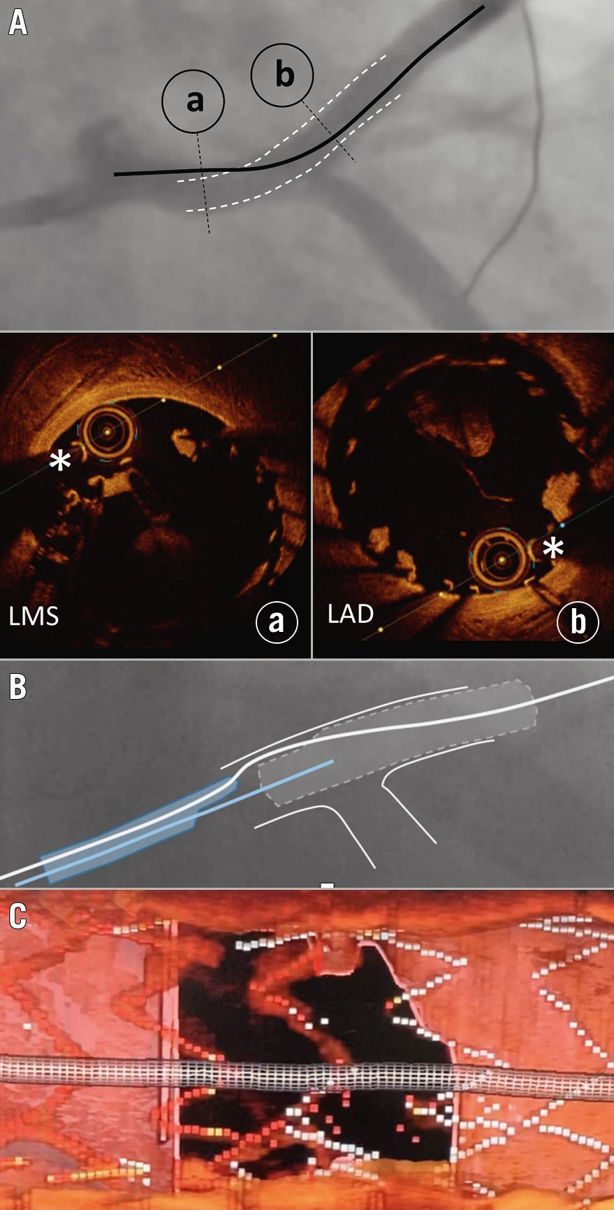
Figure 4. OCT-guided rescue following undersized stent deployment from the LAD into the LM and loss of the original wire position. A) Abluminal left main stem (LMS) wire position (black line) with the luminal position in the LAD stent segment (white dotted lines). Cross-sectional OCT imaging of the LMS (a) and LAD (b) demonstrate abluminal and luminal wire positions (white asterisks), respectively. B) Use of a dual lumen catheter, loaded on the abluminal wire (white line), facilitating passage of a second wire (blue line) through the true lumen of the stent, confirmed using 3D bifurcation OCT software (C). LAD: left anterior descending coronary artery; LM: left main; OCT: optical coherence tomography
2) The catheter stops inside the pMV stent at the level of the SB/aSB origin (Figure 5, Panel 4b)
Mechanism
SB/aSB rewiring can require excessive wire manipulations that are associated with an increased risk of wire wrap. When this happens, it is often responsible for the hold-up of the catheter inside the pMV at the level of the SB/aSB ostium and can be overcome as described previously in section (A). In addition, sometimes it is difficult to find a good angiographic projection to identify the origin of the SB/aSB, which increases the chances of SB/aSB rewiring not through the recommended distal strut but through a proximal strut (Figure 5, Step 3). In this case, the subsequent KBI (Figure 5, Step 4) will result in an unfavourable MV stent deformation with creation of a neo-carina (Figure 5, Step 4, arrowhead) that can be difficult to recognise by simple angiography. A subsequent re-POT performed (incorrectly in this circumstance) with the balloon positioned close to the carina will trap intraluminally the SB/aSB wire by repositioning (pushing) the segment of the MV stent that was moved away from the SB/aSB ostium (by the prior KBI) in its original position28 (Figure 5, Panel 4a, arrowhead). If additional balloon/stent treatments or IVUS/OCT of the SB/aSB are required, the access by any (balloon/stent/imaging) catheter into the SB/aSB will be obstructed; in this case the catheter will enter the pMV but will stop at the SB/aSB ostium (Figure 5, Panel 4b), where the SB/aSB wire was trapped by the too distal re-POT.
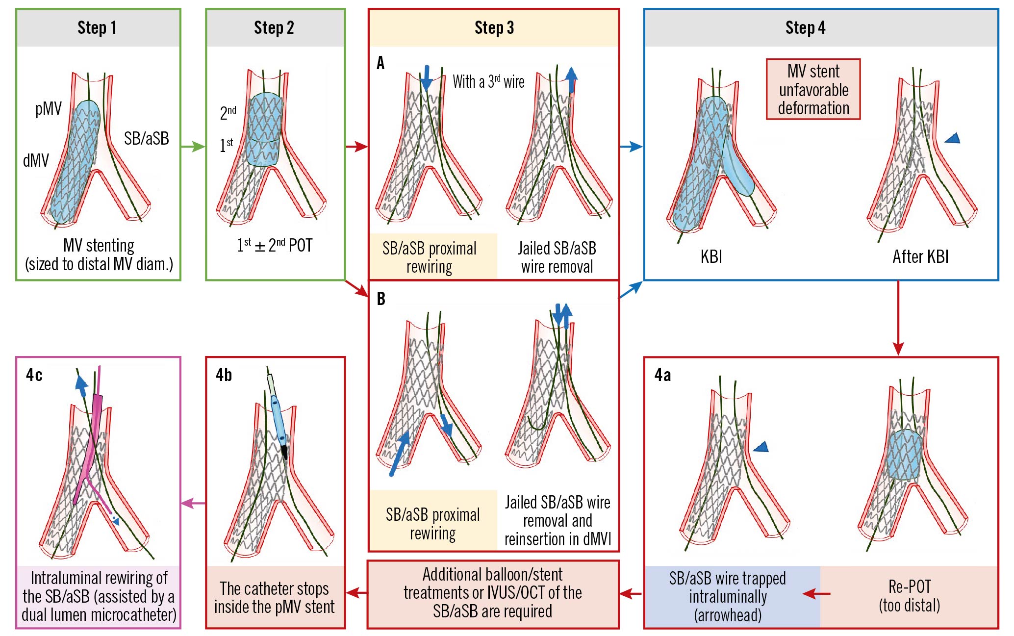
Figure 5. The catheter stops inside the pMV stent at the level of the SB/aSB origin (after proximal rewiring, KBI and distal POT). See main text for detailed description. The green arrow and image borders denote the optimal steps. The red arrows and image borders denote where potential mistakes may occur (pitfalls). The violet arrow and image border denote the corrective step that arises from the pitfall. The light blue arrows and image border denote the step commonly performed, not suspecting the previous pitfall. dMV: distal main vessel; IVUS: intravascular ultrasound; KBI: kissing balloon inflation; OCT: optical coherence tomography; pMV: proximal main vessel; POT: proximal optimisation technique; SB/aSB: side branch/assigned side branch
Troubleshooting
The solution to this problem is intraluminal rewiring of the SB/aSB through the recommended distal strut, preferably assisted by the use of a dual lumen microcatheter advanced on the MV wire (Figure 5, Panel 4c).
Prevention
To avoid this pitfall, we recommend the avoidance of any distal re-POT and to perform only a proximal re-POT. In addition, the optimal recrossing point in the distal strut can be assessed by 3D OCT29. When the wiring position is not optimal, repositioning of the wire may be considered.
3) The catheter stops in the aorta at the edge of an ostial LM stent (Figure 6B)
Mechanism
This only occurs for LM stenting when the aim of the operator is to completely cover the LM ostium. Commonly, the LM stem originates from the aorta with an angle <80 degrees and, to completely cover the “roof” of the LM ostium, the stent should be delivered with a small asymmetric protrusion of the inferior segment into the aorta, using a 20-25° cranial view (between right anterior oblique [RAO] 10° and left anterior oblique [LAO] 40°)30, thereby increasing the probability that the 3rd wire, commonly used to rewire the SB/aSB after POT, enters the LM stent abluminally, through this small stent protrusion in the aorta (Figure 6A). A recent study31 demonstrated that an excessive stent overexpansion by POT, commonly needed during LM stenting, resulted in a 2.2 mm pMV stent elongation for each 1 mm of absolute overexpansion by POT. This phenomenon may lead to dynamic stent protrusion further into the aorta, associated with a higher probability of entering the LM stent abluminally during rewiring and with the potential of longitudinal stent distortion caused by the guiding catheter manipulation. Most of the time both LM stent abluminal rewiring and longitudinal LM stent distortion cannot be recognised by simple angiography but may be suspected if there is an awareness of friction during wire manipulation and can be identified by intracoronary imaging, as shown in Figure 7 using OCT. In the case of simple LM stent abluminal rewiring, which is not complicated by longitudinal stent deformation, a new balloon could cross abluminally from the aorta into the LM and be advanced into the SB/aSB without excessive friction. SB/aSB balloon dilatation or KBI can also be performed followed by a re-POT and stent “flaring” at the LM ostium. If the SB/aSB angiographic result is acceptable the operator can finish the procedure, pulling out the SB/aSB wire (that crossed abluminally) without excessive friction. However, where it is necessary to instrument the SB/aSB, advancement of devices into the LM will be obstructed: the catheter will stop in the aorta at the proximal edge of the LM stent at the site where the LM was abluminally rewired (Figure 6B).
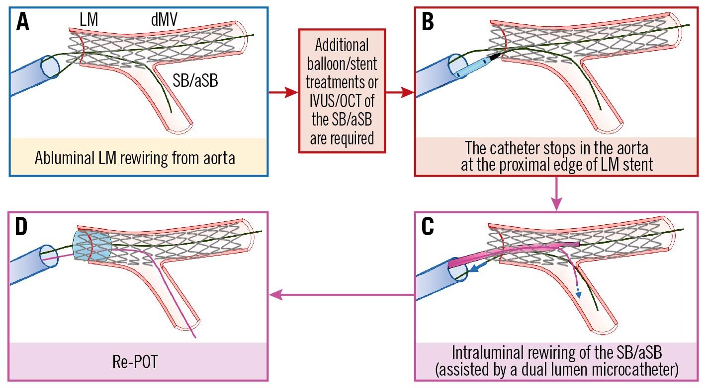
Figure 6. The catheter stops in the aorta at the edge of an ostial LM stent. See main text for detailed description. The light blue image border denotes the step commonly performed, not suspecting the previous pitfall. The red arrows and image borders denote where potential mistakes may occur (pitfalls). The violet arrows and image borders denote the corrective steps that arise from the pitfalls. dMV: distal main vessel; IVUS: intravascular ultrasound; LM: left main; OCT: optical coherence tomography; POT: proximal optimisation technique; SB/aSB: side branch/assigned side branch
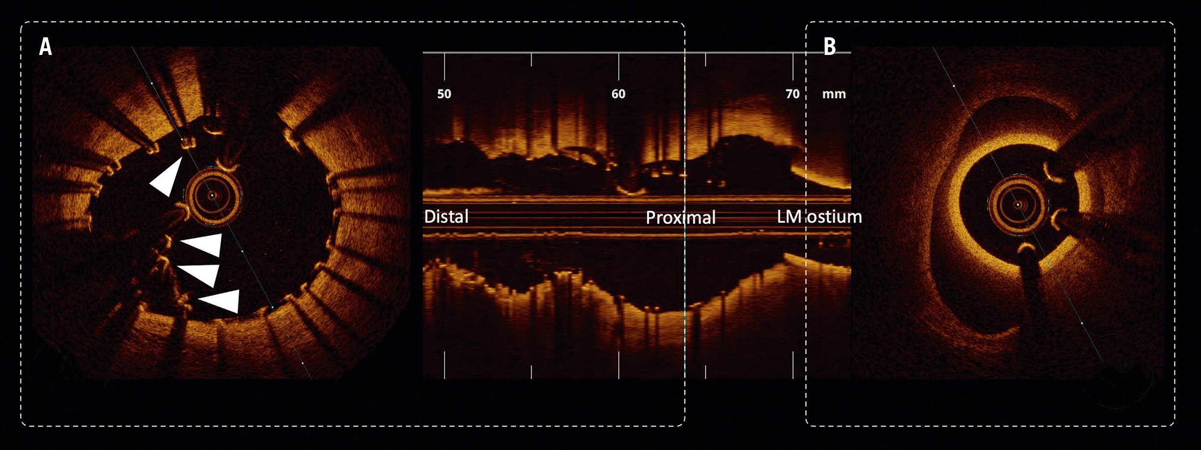
Figure 7. ICI-identified longitudinal LM stent deformation. A) Acute disruption of a self-expanding nitinol stent device within the LM – disrupted and malapposed struts highlighted with white triangles. B) Guide catheter engaged in an eccentric LM ostium. LM: left main
Troubleshooting
Most importantly, the operator should not attempt to increase the guiding catheter support and/or try to re-engage the LM due to the risk of causing/worsening longitudinal LM stent deformation. Therefore, once the problem is identified it should be immediately corrected by re-POT followed by intraluminal rewiring of the SB/aSB, preferably assisted by the use of a dual lumen microcatheter (Figure 6C) or by a microcatheter with a fixed or deflectable tip and followed by a final re-POT (Figure 6D). This solution can be unsuccessful due to ostial SB/aSB dissection. This risk is reduced if the operator follows the rule of not predilating the SB/aSB, as suggested above in stage B, and selecting an “inverted PS” approach when SB/aSB predilatation is deemed necessary, providing that the selected stent platform has an expansion capacity compatible with the larger diameter of the LM stem32.
Prevention
The use of the POT balloon to reposition the guiding catheter can facilitate adequate catheter engagement after stenting the ostial LM and can be useful to decrease the chances of abluminal rewiring. To avoid a longitudinal LM stent deformation after a possible unrecognised accidental LM abluminal rewiring, we recommend a manoeuvre of withdrawing the guiding catheter into the aorta (“disengagement”) when removing the balloons used for KBI, the POT balloon or the potentially trapped SB/aSB wire. To avoid pMV stent elongation due to excessive stent overexpansion by POT, 2 solutions have been proposed31: 1) rather than aiming for a perfect marker-on-carina position of the POT balloon, a modified (somewhat more proximal) position should be considered, adapted to the diameter mismatch and conus length of the available balloon; and 2) instead of aiming for a perfect aorto-ostial position of the stent, potential proximal elongation should be accounted for, with positioning of the stent slightly within the ostium of the LM.
Conclusions
The PS strategy is a treatment philosophy that provides a dynamic approach to the treatment of the majority of true CBL, starting with the implantation of a single stent in one branch, with careful assessment and treatment of the SB/aSB, and with stenting only when required. However, despite its intended simplicity and versatility, evolution of the approach over many years has generated new technical and procedural challenges for the operator to consider. In order to achieve optimal outcomes for our CBL patients it is important to acknowledge the pitfalls and consider approaches to overcome complications encountered for every procedural step. Part I of this 16th EBC consensus document provides a detailed overview of the pitfalls and troubleshooting of this strategy for the treatment of true CBL during the implantation of the first stent.
Conflict of interest statement
R. Albiero has received speaker fees from Medtronic, and Abbott. F. Burzotta has received speaker fees from Medtronic, Abiomed, Abbott, and Terumo. J.F. Lassen has received speaker fees from Medtronic, Boston Scientific, Biotronik, Abbott, and Biosensors. A.P. Banning declares institutional funding of a fellowship from Boston Scientific and has received speaker fees from Boston Scientific, Abbott, Medtronic, Philips/Volcano, and Miracor. T.W. Johnson has received speaker fees from Abbott, Boston Scientific, Medtronic, and Terumo and institutional funding for fellowships from Boston Scientific, and Terumo. D. Hildick-Smith has received ad board/consultancy/research funding from Terumo, Medtronic, Abbott, and Boston Scientific. M. Pan has received speaker fees from Abbott, Terumo, and Volcano. A. Chieffo has received speaker fees from Abiomed, and GADA. O. Darremont has received speaker fees from Edwards Lifesciences. Y.S. Chatzizisis has received speaker fees/consultancy/research funding from Boston Scientific, and Medtronic. G. Stankovic has received speaker fees from Medtronic, Abbott, Boston Scientific, and Terumo. T. Lefèvre has received speaker or proctorship fees from Abbott, Boston Scientific, Terumo, and Edwards Lifesciences. The other authors have no conflicts of interest to declare.
Supplementary data
To read the full content of this article, please download the PDF.