Abstract
The European Bifurcation Club (EBC) supports a continuous review of the field of coronary artery bifurcation interventions and aims to facilitate a scientific discussion and an exchange of ideas on the management of bifurcation disease. The recent focus of meetings and consensus statements has been on the technical issues in bifurcation stenting, recognising that the final result of a bifurcation procedure and the long-term outcome for our patients are strongly influenced by factors, including preprocedural strategy, stenting technique selection, performance of optimal procedural steps, the ability to identify and correct complications and finally, and most important, the overall performance of the operator. Continuous refinement of bifurcation stenting techniques and the promotion of education and training in bifurcation stenting techniques represent a major clinical need. Accordingly, the consensus from the latest EBC meeting in Brussels, October 2021, was to promote education and training in bifurcation stenting based on the EBC principle. Part II of this 16th EBC consensus document aims to provide a step-by-step overview of the pitfalls and technical troubleshooting during the implantation of the second stent either in the provisional stenting (PS) strategy or in upfront 2-stent techniques (e.g., 2-stent PS pathway and double kissing crush stenting). Finally, a detailed overview and discussion of the numerous modalities available to provide continuous education and technical training in bifurcation stenting techniques are discussed, with consideration of their future application in enhancing training and practice in coronary bifurcation lesion treatment.
Introduction
Stepwise layered provisional stenting (PS) is recommended by the European Bifurcation Club (EBC) as the preferred strategy to treat coronary bifurcation lesions (CBL), with the intention to keep the procedure as simple as possible and aiming to minimise the number of stents needed in a bifurcation lesion1.
The PS strategy is recommended both when the use of a single stent is planned and also when the use of 2 stents is anticipated preprocedurally12. The benefit of 2-stent techniques for treating a complex CBL with a long (>10 mm) diseased side branch/assigned side branch (SB/aSB) was evaluated in the multicentre, randomised DEFINITION II trial3, where a systematic 2-stent approach was associated with a significant improvement in clinical outcomes compared with the PS approach. However, we reiterate that the simpler 1-stent approach is also appropriate for the treatment of a true CBL with a shorter SB/aSB lesion length (<10 mm), as demonstrated by the results of the EBC MAIN trial4.
Implantation of the first stent in the PS influences the next steps in the procedure if SB/aSB stenting (such as T-stenting, T and small protrusion [TAP] or culotte techniques1) is needed5.
The first stent will most likely have an impact on the final result of the procedure and full attention should be paid to reach the most optimal and favourable implantation result5. It is recommended to stent the most diseased branch first when PS is used as an upfront 2-stent strategy. Accordingly, the first stent in PS can be implanted as part of the “A” family of the "Main, Across, Distal, Side" (MADS-2) classification (main Across side first=standard PS; Across distal main first=inverted PS)2.
A second stent may be required in 5 to 25% of cases in the PS strategy12. The selected stent implantation technique depends on the lesion characteristics, side branch importance, access towards the most distal strut and level of residual SB stenosis tolerated by the operator1(Central illustration). When the SB ostium appearance is optimal, a second SB/assigned side branch (aSB) stent can be implanted in a T-shape configuration without protrusion into the main vessel (MV)1 (Figure 1, Step 1 to Step 4) if SB/aSB ostium scaffolding from the MV stent is optimal. When the SB/aSB ostium appearance is not clearly visible or not optimal (usually due to access through a proximal strut), TAP stenting (Figure 2, Step 1 to Step 4) or the culotte or double kissing (DK)-culotte technique (Figure 3, Step 1 to Step 5) can be performed, according to operator preference1. The inverted DK-culotte (Figure 4, Step 1 to Step 5) and DK-crush (Figure 5, Figure 6, Step 1 to Step 10), as well as inverted T-stenting and TAP, can be considered if 2 stents are planned upfront. Unlike DK-crush, the PS approach maintains an option to limit treatment to a single stent where appropriate.
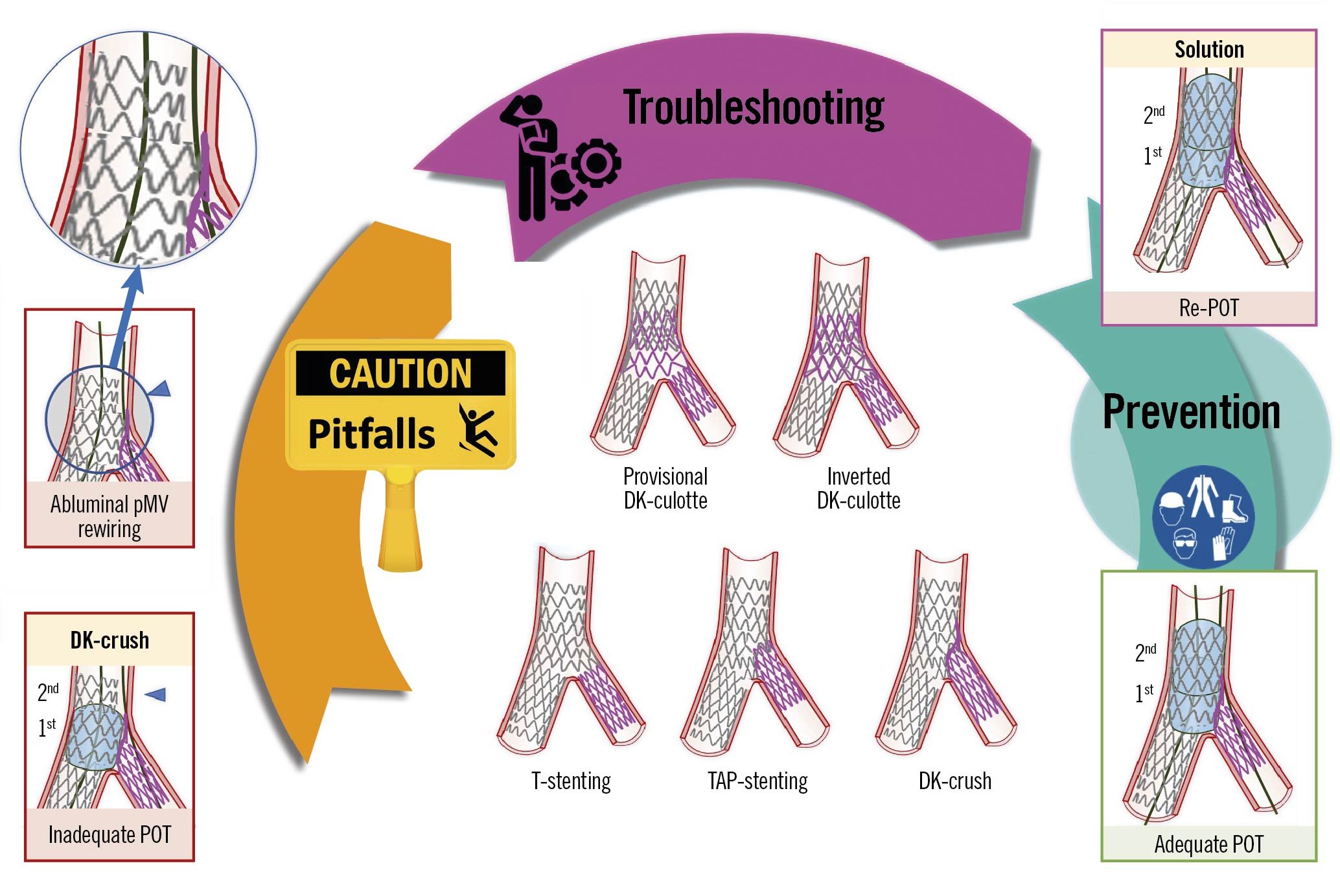
Central illustration. Step-by-step two-stent implantation according to provisional or DK-crush. Pitfalls, step-by-step technical troubleshooting and pitfall prevention during two-stent implantation according to the provisional or DK-crush approaches for the treatment of coronary bifurcation lesions. An example pitfall is shown in the left panels. The red image borders denote where the pitfall occured. The panel on the right with a violet border denotes the corrective step required by the pitfall. The panel on the right with a green border denotes how to prevent the pitfall. DK-crush: double kissing crush; DK-culotte: double kissing culotte; pMV: proximal main vessel; POT: proximal optimisation technique; TAP-stenting: T and small protrusion stenting
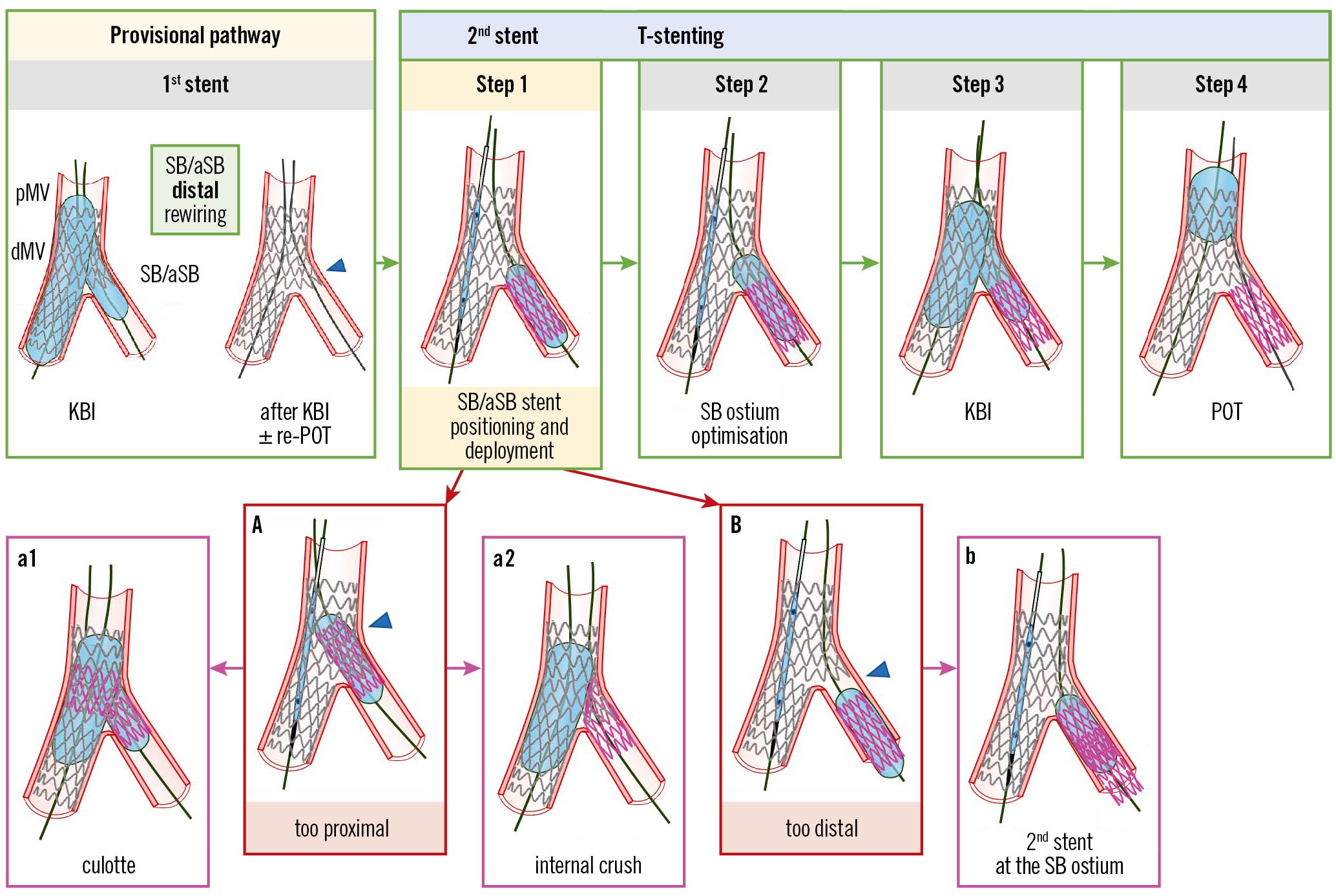
Figure 1. Procedural steps and pitfalls of the T-stenting technique. From left to right the recommended steps of the 2nd stent implantation according to the principles of the T-stenting technique are depicted: (Step 1) SB/aSB stent positioning and deployment; (Step 2) SB/aSB ostium optimisation; (Step 3) KBI; (Step 4) final POT. The main pitfall is related to SB/aSB stent positioning and deployment (Step 1), with the risk of too proximal (A) or too distal (B) stent deployment, which may be corrected by proceeding with the steps of culotte (a1) or internal crush (a2) when the stent was deployed too proximally, or by additional stent implantation to cover the SB/aSB ostium (b), when the stent was deployed too distally. The green arrows and image borders denote the optimal steps. The red arrows and image borders denote where potential mistakes may occur (pitfalls). The violet arrows and image borders denote the corrective steps that arise from the pitfalls. dMV: distal main vessel; KBI: kissing balloon inflation; pMV: proximal main vessel; POT: proximal optimisation technique; SB/aSB: side branch/assigned side branch
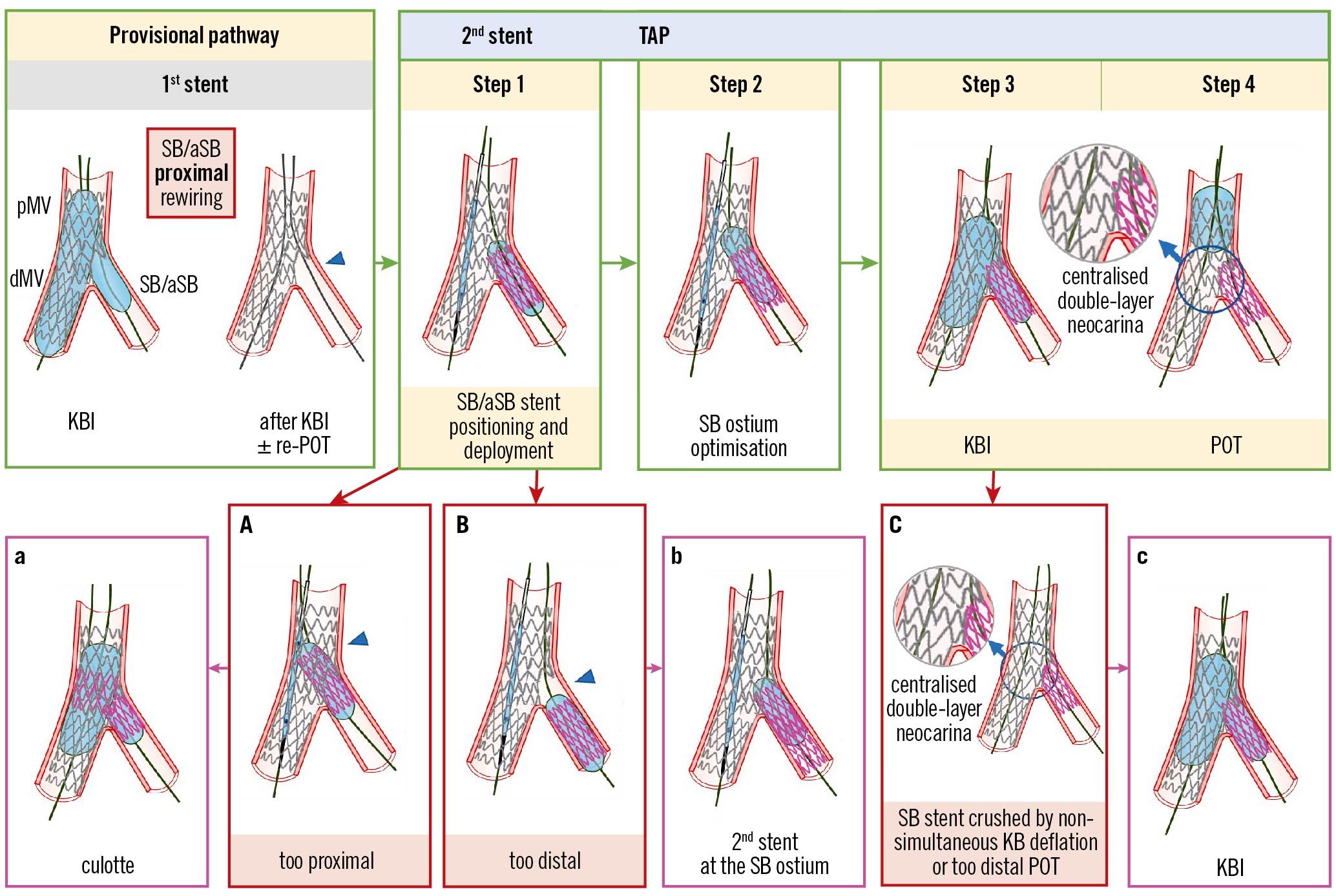
Figure 2. Procedural steps and pitfalls of the TAP-stenting technique. From left to right the recommended steps of the 2nd stent implantation according to the principle of the TAP technique are shown: (Step 1) SB/aSB stent positioning and deployment; (Step 2) SB/aSB ostium optimisation; (Step 3) KBI; (Step 4) final POT. The main pitfall is related to SB/aSB stent positioning and deployment (Step 1), with the risk of too proximal (A) or too distal (B) stent deployment, which may be corrected by proceeding with the steps of culotte (a) or internal crush when the stent was deployed too proximal, or by additional stent implantation to cover the SB/aSB ostium (b), when the stent was deployed too distally. At Steps 3 and 4, asynchronous kissing balloon deflation or too distal POT may contribute to a displacement of metallic neocarina (C), which can be corrected with repeated KBI followed by simultaneous deflation of the kissing balloons (c). The green arrows and image borders denote the optimal steps. The red arrows and image borders denote where potential mistakes may occur (pitfalls). The violet arrows and image borders denote the corrective steps that arise from the pitfalls. dMV: distal main vessel; KBI: kissing balloon inflation; pMV: proximal main vessel; POT: proximal optimisation technique; SB/aSB: side branch/assigned side branch; TAP: T and small protrusion
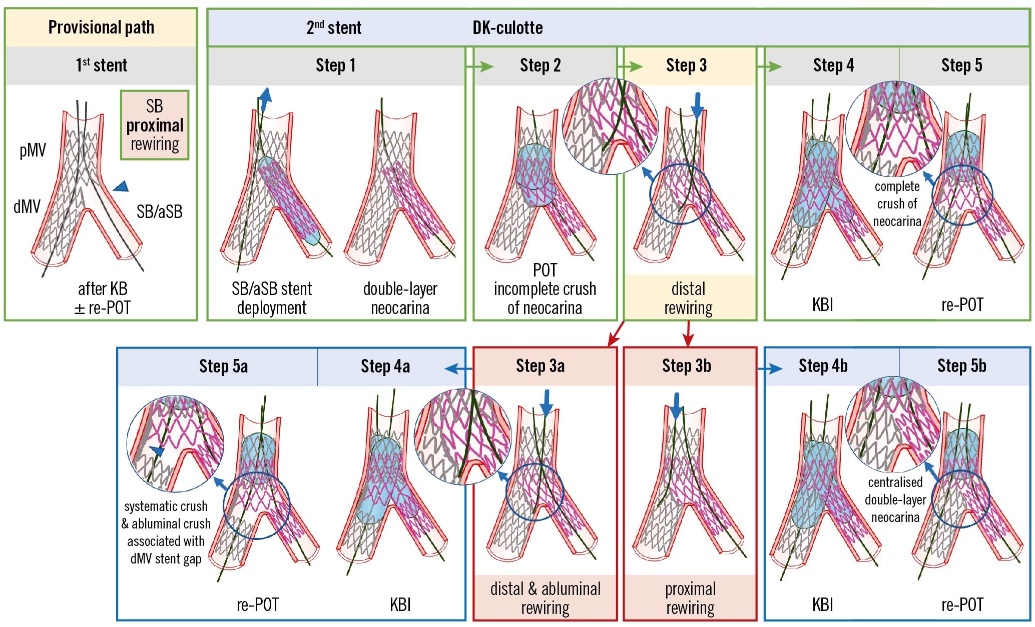
Figure 3. Recommended steps for implantation of the 2nd stent with the DK-culotte technique in the provisional pathway (upper panels). Pitfalls related to Step 3 which are difficult to recognise by simple angiography (lower panels). From left to right the recommended steps of the 2nd stent implantation according to the principle of DK-culotte technique are shown: (Step 1) second SB/aSB stent implantation across the first MV stent with a diameter selected 1:1 according to the SB/aSB size, and a length selected to ensure SB/aSB lesion coverage; (Step 2) complete POT with a balloon diameter sized 1:1 according to the pMV; (Step 3) distal rewiring of the first stent with a 3rd wire according to the pullback technique; (Step 4) KBI (using short NC balloons) is systematically performed. Usually, after having placed the 2 balloons in the proper position, sequential inflation at high pressure followed by simultaneous kissing balloon deflation is suggested; (Step 5) final re-POT. The 2 pitfalls described pertain to the position of the wire recrossing into the first stented MV after implantation of the second SB/aSB stent (Step 3). In case of abluminal recrossing, i.e., outside of the dMV stent contour (Step 3a), the subsequent steps may lead to struts of the dMV stent being pushed towards the lateral dMV wall, thus creating a gap distal to the carina (Steps 4a and 5a). Proximal rewiring following the implantation of the second SB/aSB stent (Step 3B), may result in a long double-layer metallic neocarina (Steps 4b and 5b). The green arrows and image borders denote the optimal steps. The red arrows and image borders denote where potential mistakes may occur (pitfalls). The light blue arrows and image borders denote the steps commonly performed, not suspecting the previous pitfalls. dMV: distal main vessel; DK: double kissing; KBI: kissing balloon inflation; MV: main vessel; NC: non-compliant; pMV: proximal main vessel; POT: proximal optimisation technique; SB/aSB: side branch/assigned side branch
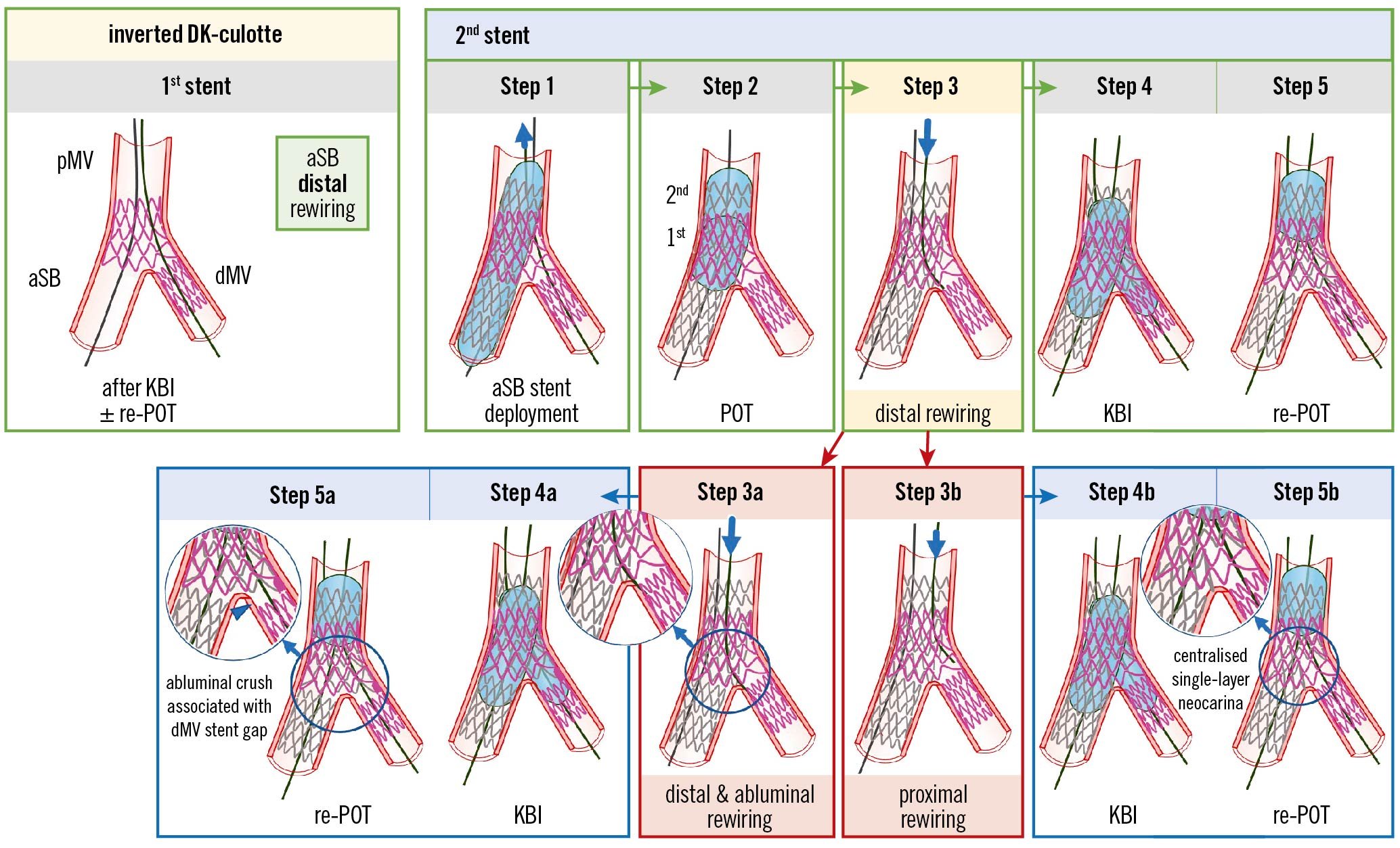
Figure 4. Recommended steps for implantation of the 2nd stent with the inverted DK-culotte technique (upper panels). Pitfalls related to Step 3 which are difficult to recognise by simple angiography (lower panels). From left to right the recommended steps of the 2nd stent implantation according to the principle of inverted DK-culotte technique are shown: (Step 1) second MV stent implantation across the first stent with a diameter selected 1:1 according to the aSB size, and a length selected to ensure pMV lesion coverage; (Step 2) complete POT with a balloon diameter sized 1:1 according to the pMV; (Step 3) distal rewiring of the first stent with a 3rd wire according to the pullback technique; (Step 4) KBI (using short NC balloons) is systematically performed. Usually, after having placed the 2 balloons in the proper position, sequential inflation at high pressure followed by simultaneous kissing balloon deflation is suggested; (Step 5) final re-POT. The 2 pitfalls described pertain to the position of the wire recrossing into the first stented branch after implantation of the second stent (Step 3). In case of distal and abluminal rewiring, i.e., outside of the first stent contour (Step 3a), the subsequent steps may lead to struts of the first stent being pushed towards the lateral dMV wall, thus creating a gap distal to the carina (Steps 4a and 5a). Proximal rewiring of the first stent following the implantation of the 2nd stent (Step 3b), may result in a long single-layer metallic neocarina (Steps 4b and 5b). The green arrows and image borders denote the optimal steps. The red arrows and image borders denote where potential mistakes may occur (pitfalls). The light blue arrows and image borders denote the steps commonly performed, not suspecting the previous pitfalls. DK: double kissing; dMV: distal main vessel; KBI: kissing balloon inflation; MV: main vessel; pMV: proximal main vessel; POT: proximal optimisation technique; aSB: assigned side branch
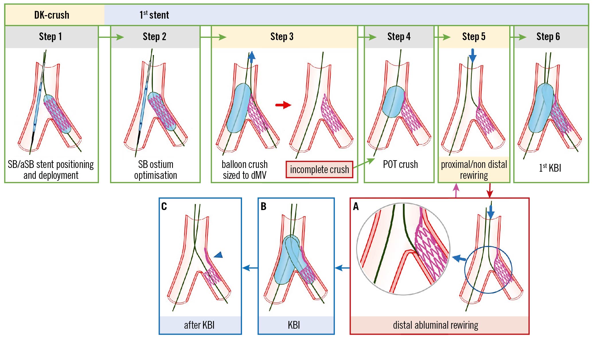
Figure 5. Recommended steps, with pitfalls and troubleshooting, for DK-crush during implantation of the first SB/aSB stent. From left to right the recommended steps of the 1st stent implantation according to the principle of the DK-crush technique are shown: (Step 1) SB/aSB stenting. While the MV balloon is kept uninflated in the MV, the stent (sized 1:1 according to SB/aSB) is implanted in the SB/aSB protruding into the proximal MV by 2–3 mm; (Step 2) SB/aSB ostium optimisation. After SB/aSB stent deployment, the balloon of the stent is slightly pulled back and repeated inflation at high pressure is performed keeping the balloon inside the MV still uninflated; (Step 3) Balloon crush. After removal of the SB/aSB stent's balloon and the SB/aSB guidewire, the protruding struts of the SB/aSB are crushed by the inflation of the balloon inside the MV sized to the dMV. This initial balloon crush is theoretically incomplete resulting in stent malapposition in the pMV; (Step 4) POT crush with a short balloon sized 1:1 to the pMV to warrant optimal crushing without pMV malapposition; (Step 5) proximal or non-distal SB/aSB rewiring; and (Step 6) first KBI using 2 non-compliant (NC) balloons sized 1:1 according to the SB/aSB and dMV diameters. The main pitfalls pertain to the position of the wire recrossing into the stent (Step 5). In case of distal abluminal rewiring, i.e., outside of the SB/aSB stent contour (Panel A), the subsequent KBI (Panel B) may lead to struts of the SB/aSB stent being pushed towards the lateral SB/aSB wall, thus creating an uncorrectable significant gap distal to the carina of the SB/aSB ostium (Panel C, arrowhead). The green image arrows and borders denote the optimal steps. The red arrow and image borders denote where potential mistakes may occur (pitfalls). The light blue arrows and image borders denote the steps commonly performed, not suspecting the previous pitfalls. The violet arrow denotes the corrective step that arises from the pitfall. DK: double kissing; dMV: distal main vessel; KBI: kissing balloon inflation; pMV: proximal main vessel; POT: proximal optimisation technique; SB/aSB: side branch/assigned side branch
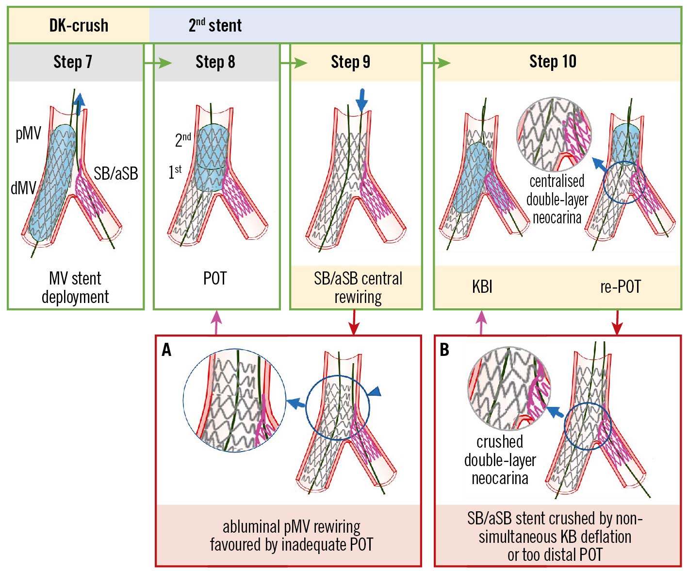
Figure 6. Recommended steps, with pitfalls and troubleshooting, for DK-crush during implantation of the second MV stent. From left to right the recommended steps of the 2nd stent implantation according to the principle of the DK-crush technique are shown: (Step 7) MV stenting. After SB/aSB guidewire removal, stent implantation across the SB/aSB take-off with a DES diameter selected 1:1 according to the dMV size is performed; (Step 8) Systematic post-dilation (1st POT) with a balloon sized 1:1 to the pMV with meticulous attention paid to POT balloon position. In case of a long stented area in the pMV, a 2nd POT balloon inflation is needed to appropriately post-dilate the entire pMV stent segment; (Step 9) SB/aSB central rewiring. The SB/aSB is rewired aiming at crossing the SB/aSB ostium through a non-distal cell. The “centrality” of rewiring should be carefully checked before further steps are done; (Step 10) second KBI and final re-POT. Simultaneous KBI at high pressure using 2 NC balloons sized 1:1 according to the SB/aSB and dMV diameters. Final re-POT: performed with a short balloon sized 1:1 to the pMV. The main pitfalls pertain to the position of wire recross into the stent SB/aSB (Step 9) and ballooning (Step 10). The case of an abluminal pMV rewiring, i.e., outside of the pMV stent contour (Panel A) is favoured by inadequate POT and can be corrected by a re-POT (violet arrow). At Step 10, asynchronous kissing balloon deflation or too distal POT may contribute to a displacement of metallic neocarina (Panel B), which can be corrected with repeated KBI (violet arrow) followed by simultaneous deflation of the kissing balloons and non-distal re-POT. The green arrows and image borders denote the optimal steps. The red arrows and image borders denote where potential mistakes may occur (pitfalls). The violet arrows denote the corrective steps that arise from the pitfalls. DK: double kissing; dMV: distal main vessel; KBI: kissing balloon inflation; MV: main vessel; NC: non-compliant; pMV: proximal main vessel; POT: proximal optimisation technique; SB/aSB: side branch/assigned side branch
Two-stent techniques
T-stenting without protrusion into the MV
The first case of T-stenting (Palmaz-Schatz [Johnson & Johnson] stent implantation through the stent struts of a previously deployed stent) was reported by Antonio Colombo in 19956. The contemporary criterion for the selection of this still unchanged technique is based on the type of deformation of the MV stent2 resulting from Step 3 (distal vs proximal SB rewiring) and Step 4 (ballooning) during the implantation of the first stent in the PS pathway, described in part I of this consensus document5. A distal crossing in Step 3 is associated with a favourable MV stent deformation after ballooning in Step 4 that allows T-stenting to be performed without SB/aSB stent protrusion in the MV, instead of TAP or DK-culotte. This favourable deformation can be evaluated by angiography using X-ray stent enhancement.
The recommended steps to perform the T-stenting technique
The procedural steps and pitfalls of the T-stenting technique are illustrated in Figure 1. For an optimal T-stent implantation, meticulous attention to the visualisation of the SB/aSB origin is needed and X-ray stent enhancement can be used to check appropriate stent positioning at the SB/aSB ostium. When the SB/aSB stent is correctly positioned, together with a deflated balloon in the MV, it is deployed (Step 1). The performance of an additional high-pressure inflation following partial withdrawal of the stent balloon (Step 2) is recommended in order to achieve optimal stent expansion2. Kissing balloon inflation (KBI) is performed immediately after the stent’s deployment using the SB/aSB stent and the MV balloons (Step 3). A final proximal optimisation technique (POT) (Step 4) may be necessary.
Pitfalls
Incorrect T-stent position
1) Too distal (Figure 1, Panel B). In this case the SB/aSB stent migrated distally during deployment, exacerbated by excessive cardiac motion, MV/ostial SB/aSB severe calcification, or the stent slipping distally during inflation due to protrusion of restenotic tissue into the vessel.
Troubleshooting: The operator may consider repeating T-stenting (Figure 1, Panel b) if the cause of the incorrect positioning of the stent is recognised and can reasonably be overcome, or they can consider converting to implant the SB/aSB stent according to the TAP or culotte techniques.
2) Too proximal (Figure 1, Panel A), due to accidental proximal protrusion into the MV, mostly due to cardiac motion, calcification or a non-optimal view of the carina.
Troubleshooting: There are 2 solutions to correct this complication: 1) conversion to a mini-culotte (Figure 1, Panel a1) when there is not a large mismatch between the SB/aSB and MV stent diameters; 2) conversion to internal crush (Figure 1, Panel a2) when the SB/aSB stent diameter is significantly smaller than the MV stent diameter. The small diameter SB/aSB stent might have a small-sized stent cell and rings, potentially leading to stent malapposition that cannot be fully corrected by the subsequent balloon dilation (including the final KBI). In particular, the MV balloon will be constrained by the rewired SB/aSB stent cell and its proximal stent rings (napkin ring formation). A case of napkin ring formation in the MV has been recently reported7. Conversion to internal crush can avoid the risk of napkin ring formation in the MV even when the SB/aSB stent diameter is not significantly smaller than the MV stent diameter, although the risk of this phenomenon is reduced with current-generation drug-eluting stents (DES) that have a very “open-cell” design with limited link connections and greater cell expansion capacity8. Consequently, an understanding of stent design is important. The following stent platforms have a greater number of link connectors in the proximal stent segment to limit the risk of longitudinal stent deformation but giving rise to smaller cell size and restricted over-expansion: Resolute Onyx (Medtronic), Orsiro (Biotronik) and SYNERGY (Boston Scientific)8. When these smaller cells are rewired, napkin ring formation is likely to occur, potentially causing significant stent malapposition in the MV with an increased risk of thrombotic complications.
Prevention: To prevent this complication, the following steps are recommended: 1) selection of an optimal angiographic view; 2) adequate preparation of the lesion in case of calcific CBL with non-compliant (NC) balloons, atherectomy and intravascular lithotripsy (IVL); 3) using a “balloon-assisted” SB/aSB T-stenting technique: leaving an inflated balloon inside the MV first, then, pulling the SB/aSB stent until it meets resistance from the inflated MV balloon, deflating that balloon followed by deploying the SB/aSB stent; and 4) using X-ray stent enhancement for optimal stent positioning.
TAP-stenting
TAP-stenting was developed and reported by Burzotta et al in 20079, with the aim of improving the T-stenting technique to ensure full ostial coverage, where bifurcation geometry prevents perfect alignment of stents and to provide a strategy to facilitate final KBI. According to the last MADS-2 classification2, TAP-stenting can be performed as the last step (Step 5, second stent implantation) of both “A” family (“provisional”) or “inverted A” family (“inverted provisional”) stenting. Thus, the first 4 steps of the PS approach, as outlined in part I of this consensus document5, must be performed; POT, distal SB/aSB rewiring and KBI are usually recommended according to TAP best practices2. Indeed, this sequence should facilitate the performance of TAP-stent implantation by enlarging the bifurcation area (polygon of confluence [POC]) and optimising the opening of side-cells.
The recommended steps to perform the TAP-stenting technique
The procedural steps and pitfalls of the TAP-stenting technique are illustrated in Figure 2. When considering a TAP-stent implantation, meticulous attention to the SB/aSB ostium visualisation is needed, and stent visualisation enhancement with X-ray imaging can be used to check the appropriate stent positioning (the final aim is to achieve a metallic carina that is as short as possible, according to the principle that “best TAP is T”). After SB/aSB stent deployment (Step 1), the performance of an additional high-pressure inflation following partial withdrawal of the stent balloon (Step 2) is recommended in order to achieve optimal stent expansion2. KBI (Step 3), performed either immediately after stent deployment using the SB/aSB stent balloon and the MV balloon or later on in the case of a need for additional high-pressure KBI with NC balloons with simultaneous balloon deflation, is pivotal to minimise the risk of metallic neocarina deviation (Figure 2, Panel C; Table 1). The last step of any 2-stent technique is represented by repeat POT (Step 4).
Pitfalls
Incorrect TAP-stent position
TAP-stenting efficacy is strongly dependent on the precision of SB/aSB stent implantation position10.
1) Although conceived to ensure ostial coverage9, unintended “too distal” stent deployment may result in a “geographical miss” at the level of the SB/aSB ostium (Figure 2, Panel B; Table 1).
Troubleshooting: The operator may consider repeating TAP (Figure 2, Panel b) if the cause for the incorrect stent delivery position is recognised and can reasonably be overcome, or can consider implanting the SB/aSB stent according to the culotte technique.
2) A more common pitfall is represented by accidental proximal protrusion into the MV (Figure 2, Panel A; Table 1).
Troubleshooting: This case of failed TAP may be converted into (1) the mini-culotte technique (Figure 2, Panel a) by post-dilating the proximal MV with a POT balloon and rewiring the distal MV in order to progress to KBI10 or (2) internal crush. We have described above, in the section on T-stenting, the criteria for choosing between these 2 approaches.
Prevention: We have described in the section on T-stenting above how to prevent this complication.
Metallic neocarina deviation
If simultaneous deflation has not been performed, neocarina shift should be suspected. Similarly, a repeat POT, positioned too distally, after TAP can also jeopardise the metallic neocarina position (Figure 2, Panel C).
Troubleshooting: The solution for this complication is to repeat KBI with simultaneous balloon deflation to reposition the neocarina centrally within the POC.
Prevention: KBI should be performed with simultaneous balloon deflation. In addition, repeat POT should be performed with careful balloon positioning proximal to the carina, or avoided when the proximal MV stent segment is too short to allow post-dilatation without carinal disturbance or proximal “geographical miss”.
TAP in-stent restenosis requiring repeat percutaneous coronary intervention
It should be emphasised that a TAP-associated neocarina is highly mobile and its length and position are often not easily estimated by angiography (especially in the case of restenosis). Furthermore, months after stent implantation, the metallic neocarina is usually endothelialised making its eventual displacement more impactful on blood flow in one of the branches.
Prevention: When repeat percutaneous coronary intervention (PCI) is needed (due to TAP in-stent restenosis), a “sequential kissing inflation technique” is recommended: balloon dilations in the bifurcation area are performed with another balloon left in the other branch. This minimises the risk of daughter vessel obstruction by struts shifting and, importantly, facilitates a final KBI to ensure that a central position of the TAP’s neocarina is achieved.
DK-culotte stenting
Several modifications of the first culotte technique, reported by Chevalier in 199811, have been implemented to develop the contemporary DK-culotte technique. According to the last MADS-2 classification2, DK-culotte stenting can be performed as the last step (Step 5, second stent implantation) of both “A” family (“provisional”) or “inverted A” family (“inverted provisional”) stenting, ending with an unplanned or planned second stent implantation, respectively (the choice to perform the inverted DK-culotte is based on the anticipated difficulty to wire the SB). Thus, the first 4 steps required for the implantation of the first stent in the provisional pathway, described in part I of this consensus document5, must be performed; POT, distal SB/aSB rewiring and KBI are usually recommended according to DK-culotte best practices2. The same 4-step approach should be adopted for the implantation of the second stent.
The recommended steps to implant the second stent using the DK-culotte technique
The recommended steps for the implantation of the second stent using the DK-culotte technique have been recently reported in an EBC-promoted paper2 and are described in detail in the upper panels of Figure 3 (Provisional DK-culotte), Figure 4 (Inverted DK-culotte).
Pitfalls
Difficulty crossing with the second stent into the unstented (SB/aSB) branch (Step 1)
This complication is generally due to a proximal rewiring of the SB/aSB followed by KBI and a “too distal” re-POT that trapped the SB/aSB wire. The mechanism of this pitfall has been described in detail in part I of this consensus document in the section entitled: “The catheter stops inside the proximal MV stent at the level of the SB/aSB origin (Figure 5, Panel 4B)”5.
Troubleshooting: The best solution to solve this problem is rewiring the SB/aSB through the recommended distal strut, preferably assisted by the use of a dual lumen microcatheter advanced on the MV wire. If unsuccessful, the inflation of an NC balloon (at a higher pressure) at the SB/aSB ostium can enlarge the stent strut. An anchoring balloon technique, inflating a short balloon in the distal segment of the first stent implanted, can be useful.
Prevention: To prevent this complication, full attention should be paid to reach the most optimal and favourable result during implantation of the first stent, as described in part I of this consensus document5, where, in particular, we recommend avoiding a distal re-POT and performing only a proximal re-POT during implantation of the first stent.
Difficulty rewiring the first stented branch after implantation of the second stent (Step 3)
Difficulty rewiring the first stented branch after implantation of the second stent may be a consequence of prior pitfalls due to the use of an undersized balloon for POT of the second stent implanted at Step 2, or an insufficiently distal POT.
Troubleshooting: Undertake an additional POT, closer to the carina and with higher pressure, to enlarge the POC. The use of more torqueable wires like SION blue (Asahi Intecc) or Fielder FC (Asahi Intecc), polymer-coated wires like Pilot 50 (Abbott) or SION black (Asahi Intecc), or dedicated wires for chronic total occlusions like Fielder XT (Asahi Intecc) or Gaia First (Asahi Intecc) can be helpful.
Prevention: Use a correctly sized balloon for POT of the second stent implanted at Step 2 with attention paid to the POT balloon position, with its distal shoulder accurately positioned immediately proximal to the carina.
Pitfalls difficult to recognise by simple angiography (Step 3)
Described in Figure 3 and Figure 4, and illustrated in the lower panels, are the pitfalls relating to Step 3 that can be difficult to recognise by angiography alone and may only be appreciated through subsequent procedural complications and/or the use of X-ray stent enhancement/intracoronary imaging modalities.
Difficult balloon crossing into the first stented branch after implantation of the second stent (Step 4)
Difficulty crossing with the balloon into the first stented branch after implantation of the second stent may be due to (1) wire wrap, (2) a proximal strut rewiring of the second stent implanted and/or (3) the use of an undersized balloon for POT of the second stent implanted at Step 2 or an insufficiently distal POT.
Troubleshooting: (1) Wire wrap can be easily overcome by withdrawing one of the wires in the guiding catheter and readvancing it without excessive torque; (2) leave the wire in place in the proximal strut and use a third wire to try and rewire closer to the carina. If unsuccessful, the anchoring balloon technique (inflating a short balloon in the distal segment of the second stent implanted) can be useful in some cases; (3) a distal re-POT with a correctly sized balloon.
Prevention: (1) Prevention of wire wrap is described in part I of this consensus document5; (2) aim for the recommended distal SB/aSB rewiring of the second stent implanted at Step 3; (3) use a correctly sized balloon for POT of the second stent implanted at Step 2 with attention paid to POT balloon position, with its distal shoulder accurately positioned immediately proximal to the carina.
Culotte in-stent restenosis requiring repeat PCI
In case of diffuse restenosis in both branches, repeat PCI is a reasonable approach. The treatment strategy may depend on the mechanism of restenosis, which can be assessed by intracoronary imaging. If the problem is related to underexpansion of the stent, it may be solved by using an NC balloon inflated at a higher pressure or IVL, followed by KBI and a drug-eluting balloon (DEB) in the MV. This last approach using a DEB is not based on clinical data.
DK-crush
Several modifications of the first crush approach reported by Colombo in 200312 have been implemented to develop the contemporary DK-crush technique. Many operators prefer this technique for the intentional (upfront) 2-stent approach in the treatment of complex CBL (with extensive SB disease and/or anticipated difficulty in reaccessing an important SB). Indeed, in a recent meta-analysis, DK-crush was superior to several other upfront 2-stent techniques, due to the more frequent ability to perform the required final KBI (99% rate vs 80-85%)13. Based on the position of the first stent implanted, DK-crush belongs to the “S” family of the MADS-2 classification of bifurcation stenting techniques2 and will always be finalised with 2 stents in the bifurcation. EBC recognises the importance of the practice of DK-crush but highlights the potential complexity of the technique where multiple steps (n=10) are required. In addition, its efficacy has been proven only when practised by operators with a high level of experience with this technique31415. Finally, the benefits of DK-crush in randomised clinical trials were demonstrated only for patients with complex true CBL (DEFINITION criteria) with a long (>10 mm) diseased SB/aSB314. Therefore, the results of these trials may not be replicable in all CBL (i.e., non-complex true CBL or with an SB/aSB lesion length <10 mm).
The general rules, pitfalls and troubleshooting of the initial 2 stages (Stage A: MV and SB wiring; Stage B: MV and SB preparation that, for DK-crush, is required in both branches in order to facilitate delivery and optimal expansion of the stents) for the treatment of any CBL with any stenting strategy, including DK-crush, have been described in part I of this consensus document5.
The recommended steps to perform the DK-crush technique
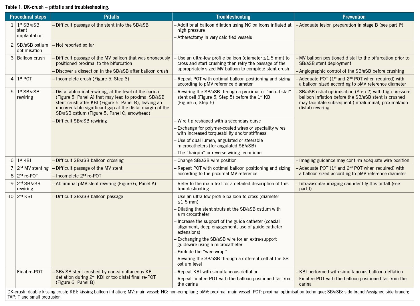
The recommended steps to perform the DK-crush technique have been recently reported in an EBC-promoted paper2 and are described in detail in Figure 5 (1st SB/aSB stent) and Figure 6 (2nd MV stent). The pitfalls and troubleshooting of each of the 10 recommended steps of DK-crush are described in Table 1. Some of them are described in more detail below.
Pitfalls
Distal SB/aSB stent abluminal rewiring before the 1st KBI
Rewiring the SB/aSB through a “distal” stent cell (Figure 5, Step 5) before the 1st KBI (Figure 5, Step 6) can result in an abluminal wire passage under the stent struts of the malapposed/crushed SB/aSB stent at the distal margin of the SB/aSB ostium (Figure 5A). The subsequent KBI may lead to struts of the proximal SB/aSB stent being pushed towards the lateral SB wall (Figure 5B), leaving an uncorrectable significant gap at the distal margin of the SB/aSB ostium (Figure 5C, arrowhead).
Prevention: Rewiring the SB/aSB through a proximal or “non-distal” stent cell (Figure 5, Step 5) before the 1st KBI (Figure 5, Step 6) is recommended to avoid this pitfall. In addition, SB/aSB ostial optimisation (Step 2) with high-pressure balloon inflation before the SB/aSB stent is crushed may facilitate subsequent (intraluminal, proximal/non-distal) rewiring.
Difficulty rewiring SB/aSB after MV stenting
The presence of multiple layers of stent struts and the deformation of cells might represent a challenge for rewiring the SB/aSB stent.
Troubleshooting: To wire the SB/aSB stent successfully, the wire tip may be reshaped with a secondary curve in order to facilitate engagement in the SB/aSB ostium. In cases of an unfavourable SB/aSB take-off angle, the “hairpin” or reverse wiring technique might be required. If wiring with a workhorse is unsuccessful, exchanging for polymer-coated wires or speciality wires with increased torqueability may be useful. The use of a microcatheter may increase wire support and allow easier reshaping and wire exchanges. For very angulated SB/aSB take-off angles, dual lumen, angulated or steerable microcatheters might be required.
Difficult SB/aSB balloon crossing after MV stenting and successful SB/aSB rewiring
After rewiring the SB/aSB, balloon crossing can also be challenging. If unable to cross with an appropriately sized balloon, a solution is to use an ultra-low profile balloon (diameter ≤1.5 mm). Other options include (1) dilating the stent struts at the SB/aSB ostium with a microcatheter; (2) increasing the support by coaxial catheter alignment, deep engagement of the guide catheter and/or the use of guide catheter extensions; (3) exchanging the SB/aSB wire for an extra-support guidewire using a microcatheter; (4) excluding the wire wrap (this requires pulling 1 wire out and rewiring); and (5) rewiring the SB/aSB through a different cell at the SB ostium level.
The following 2 pitfalls can be difficult to recognise by simple angiography and are suspected only when an unexpected event occurs during the different steps of the procedure or when X-ray stent enhancement and/or intravascular ultrasound (IVUS)/optical coherence tomography (OCT) are performed.
Abluminal proximal MV (pMV) stent rewiring
The abluminal pMV stent rewiring is made possible by a malapposition in the proximal segment of the pMV stent (Figure 6A) resulting from an inadequate POT (Figure 6A, arrowhead). A POT is defined as inadequate when, after the mandatory 1st POT balloon inflation, the more proximal 2nd POT (indicated16 when the pMV stent is longer than the POT balloon length) was not performed or was performed incorrectly, using a POT balloon too small or positioned too distally, missing the proximal stent edge. In case of suspicion of an abluminal pMV stent rewiring, intravascular imaging (IVUS/OCT) can confirm the abluminal pMV wire position and identify this pitfall.
Troubleshooting: Re-POT with optimal balloon positioning and sizing according to pMV reference diameter.
Prevention: The key to preventing any abluminal rewiring in the proximal segment of the pMV stent is to perform an adequate POT, preferably assisted by X-ray stent enhancement angiographic visualisation that can increase the precision of POT balloon positioning.
SB/aSB stent crushed by non-simultaneous balloon deflation during 2nd KBI or too distal final POT
When performing the 2nd KBI, it is pivotal to achieve simultaneous balloon deflation to minimise the risk of double-layer metallic neocarina deviation (Figure 6B). If simultaneous deflation has not been performed and/or the re-POT was too distal, neocarina deflection should be suspected.
Troubleshooting: Repeat KBI with simultaneous deflation followed by a not too distal re-POT (Step 10) is recommended to achieve the best final configuration.
Prevention: KBI should be performed with simultaneous balloon deflation. In addition, repeat POT should be performed with the balloon positioned far from the carina.
Education and continuous training in bifurcation stenting
The final result of a bifurcation procedure and the long-term outcome for the patients are strongly influenced by factors including preprocedural strategy, stenting technique selection, performance of optimal procedural steps, ability to identify and correct complications and finally, and most important, the overall performance of the operator. The understanding of the different technical steps in a procedure, the ability to avoid pitfalls and identify technical complications, and the knowledge and skills required to correct them will enhance the quality and safety of the procedures and represents a major clinical need. Thus, a technical standardisation and refinement of procedures and techniques is needed along with the appropriate training. Accordingly, the EBC recommends continuous development of bifurcation stenting strategies and promotes teaching, training and education, as well as identification of pitfalls, how to solve them when they occur and how to prevent them.
Methods for education and continuous training in bifurcation stenting
The complexity and diversity of patient, procedural and technical factors influencing a CBL intervention challenge operators in anticipating and overcoming complications. The development of heuristics, to optimise outcomes, relies on both technical experience and an ability to anticipate what is best for the patient, both in the acute periprocedural and long-term phase of treatment. The overarching goal of the EBC is to facilitate scientific discussion in the treatment of bifurcation lesions and ultimately lay the foundations for training and educating fellows and junior operators, as well as securing and maintaining the skills of senior operators. There are many tools that can be utilised to facilitate a better understanding of the overall strategy of PCI in CBL stenting, enhancing both conceptual considerations and heuristics. This includes the use of virtual reality, direct visualisation, benchtop testing and segmented computed tomography (or other imaging modalities). Much of the benchtop testing that has been conducted in silicone tubes has been the foundation for visualising and understanding stent behavior and the mechanical properties in bifurcation stenting (Table 2).
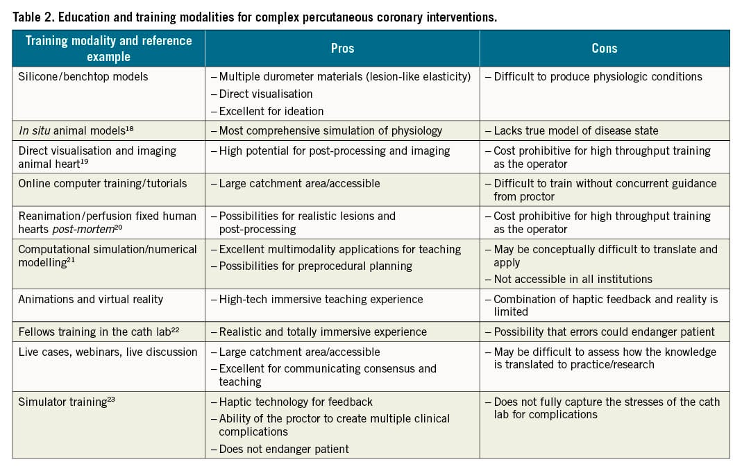
Table 2 describes the current modalities and examples of training that range from online learning tools to hands-on training. As evidenced by the “pros and cons” section of Table 2, there is no single modality that achieves all the goals of CBL training; instead the multiple modalities should be used in combination to provide a comprehensive understanding. Table 3 provides an overview of the educational characteristics provided by each modality, with a moderate rating (±) indicating a balance between an element that accurately simulates or fails to reflect the clinical scenario but, overall, provides some educational benefit.
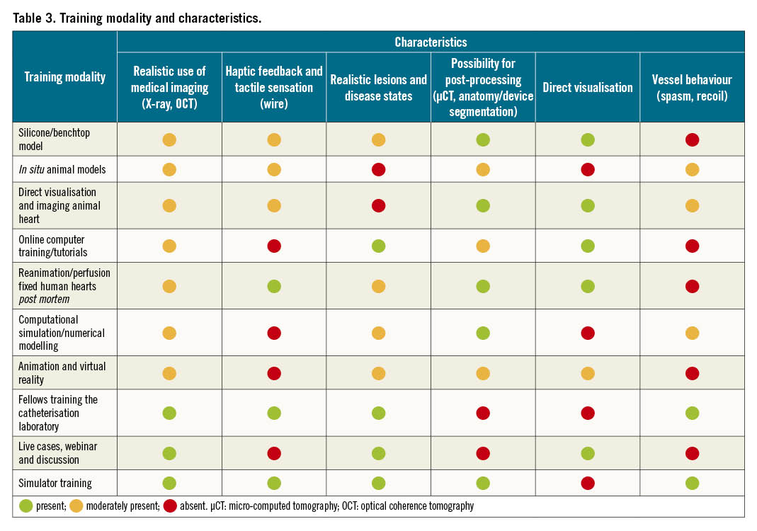
There are a vast array of training modalities (Table 2, Table 3) available to support the conceptual and procedural skill-based educational needs to enhance bifurcation treatment. Based upon the characteristics and ratings outlined in Table 3, the Mentice simulator scores best for training. The Mentice simulator has demonstrated the highest levels of efficacy in solidifying deep learning and knowledge transfer from one situation to another (complications), specifically for the use of training for complex PCI bifurcation lesions that can be repeated and achieve high throughput for certification purposes. This is also the only known modality for PCI that encompasses the haptic feedback, proctor control and real-time imaging, outside clinical practice. Finally, the Mentice simulator provides the training milieu that comes closest to a real clinical setting.
Further discussion on the need for clinical certification and re-certification is needed, but simulation-based education will play an important role in improving patient safety through avoidance of or an enhanced ability to overcome complications. In combination with other modes of computational simulation and numerical modelling we can aspire to even more realistic simulations to enhance CBL education and training.
Conclusions
EBC recommends the stepwise layered PS as the preferred strategy to treat CBL, not only when the use of a single stent is planned but also when a final use of 2 stents is anticipated before the procedure12. The PS strategy is a philosophy that aims to keep the procedure as simple as possible and to reduce the number of needed stents in a CBL1. Although there have been mixed results regarding the long-term efficacy and safety between 1-stent versus 2-stent approaches in all-cause mortality, the strategy to treat true CBL (Medina classification 1,0,1; 1,1,1; 0,1,1) with the implantation of a single stent is supported by the results of a meta-analysis of randomised trials demonstrating that a 1-stent approach is associated with a reduction in all-cause mortality at follow-up (>1 year) compared with the upfront use of more complex 2-stent bifurcation strategies17. Part II of this 16th EBC consensus document provides a step-by-step overview of the pitfalls and technical troubleshooting during the implantation of the second stent in the PS strategy, when needed, and during stent implantation in upfront 2-stent techniques (2-stent PS pathway and DK-crush stenting), when planned. Finally, a detailed overview and discussion of the different available modalities in continuous education and technical training in bifurcation stenting techniques are discussed and a future direction for training is recommended.
Conflict of interest statement
J.F. Lassen has received speaker fees from Medtronic, Boston Scientific, Biotronik, Abbott, and Biosensors. R. Albiero has received speaker fees from Medtronic, and Abbott. T.W. Johnson has received speaker fees from Abbott, Boston Scientific, Medtronic, and Terumo and institutional funding for fellowships from Boston Scientific, and Terumo. F. Burzotta has received speaker fees from Medtronic, Abiomed, Abbott, and Terumo. T. Lefèvre has received speaker or proctorship fees from Abbott, Boston Scientific, Terumo, and Edwards Lifesciences. M. Pan has received speaker fees from Abbott, Terumo, and Volcano. A.P. Banning declares institutional funding of a fellowship from Boston Scientific and has received speaker fees from Boston Scientific, Abbott, Medtronic, Philips/Volcano, and Miracor. Y.S. Chatzizisis has received speaker fees/consultancy/research funding from Boston Scientific, and Medtronic. O. Darremont has received speaker fees from Edwards Lifesciences. D. Hildick-Smith has received advisory board/consultancy/research funding from Terumo, Medtronic, Abbott, and Boston Scientific. G. Stankovic has received speaker fees from Medtronic, Abbott, Boston Scientific, and Terumo. The other authors have no conflicts of interest to declare.
Supplementary data
To read the full content of this article, please download the PDF.