
Abstract
Aims: Transcatheter mitral valve replacement (TMVR) is an emerging technology with the potential to treat patients with mitral regurgitation at excessive risk for mitral valve surgery. Geometrical measurements of the mitral valvular complex may have implications for the design of TMVR devices and for patient selection. This study sought to quantify the dynamic geometry of the mitral valvular complex in patients with significant functional mitral regurgitation (FMR) using multi-slice computed tomography (MSCT).
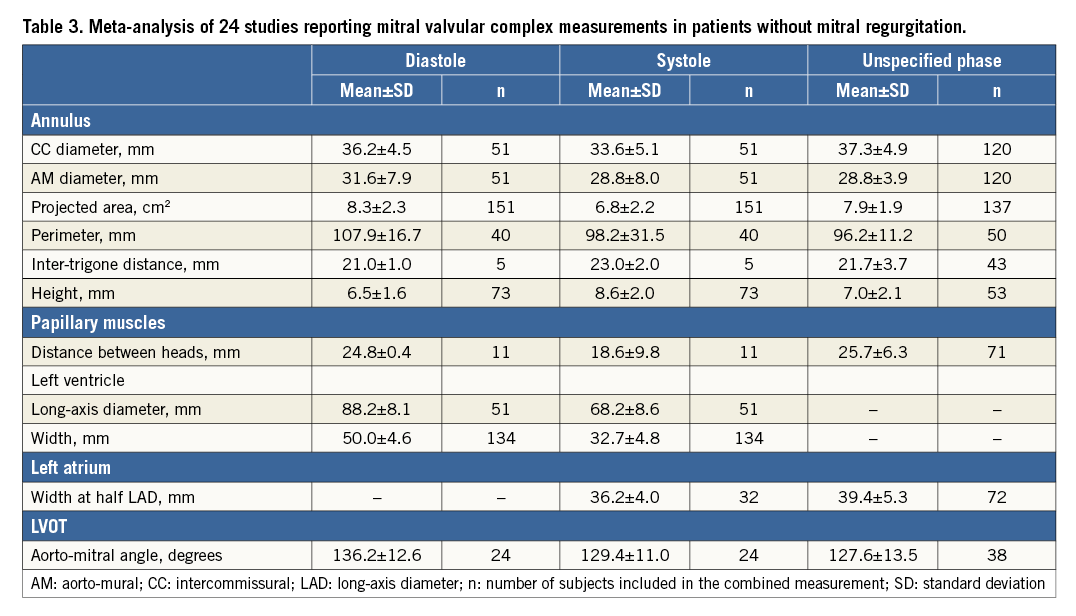
Methods and results: MSCT images were acquired in 32 patients with symptomatic, significant FMR. Two independent observers analysed image sets using a dedicated software package and a standard measurement methodology. In patients with FMR, the mean mitral annulus intercommissural and aorto-mural diameters were, respectively, 41.5±5.2 mm and 38.7±5.9 mm in systole, and were 41.5±4.4 mm and 40.0±4.7 mm in diastole. In patients without MR, the diameters were, respectively, 33.6±5.1 mm and 28.8±8.0 mm in systole, and 36.2±4.5 mm and 31.6±7.9 mm in diastole. The obstacle-free zone below the mitral annulus averaged more than 20.0 mm and varied by less than 1 mm between systole and diastole, which is not statistically significant. The aorto-mitral angle was 129.7±10.5° in systole and 131.0±9.4° in diastole.
Conclusions: The mitral annulus is larger in dimension, more circular, and less dynamic in patients with FMR. The obstacle-free zone below the mitral annulus is relatively constant during the cardiac cycle. Measurements of the mitral valvular apparatus vary considerably between patients, which suggests that tridimensional imaging will play an important role in the sizing of TMVR devices.
Abbreviations
LVOT: left ventricular outflow tract
MPR: multi-planar reconstruction
MSCT: multi-slice computed tomography
TAVR: transcatheter aortic valve replacement
TMVR: transcatheter mitral valve replacement
Introduction
Mitral regurgitation (MR) is the most prevalent valvular heart disease in adults1. Unfortunately, due to advanced disease or comorbidities, patients are often never operated surgically. To fill this therapeutic gap, and bolstered by the success of transcatheter aortic valve implantation (TAVI)2, a substantial effort has been directed towards the development of transcatheter mitral valve implantation. A handful of patients have recently been treated with experimental transcatheter mitral valves in Denmark (2012), Canada (2014), and the United Kingdom (2014).
The mitral valvular complex includes the mitral annulus, mitral leaflets, papillary muscles, the left ventricle and the left atrium3. The complex may also interact with the left ventricular outflow tract (LVOT). These structures undergo several geometrical modifications in patients with MR4. Some of these changes, regardless of their contribution to the pathogenesis of MR, may be critical in the context of transcatheter mitral valve therapies.
The high spatial and temporal resolution of multi-slice computed tomography (MSCT) makes this imaging modality an ideal tool to study the geometry of the mitral valvular complex. Herein, we apply a systematic MSCT measurement methodology specifically designed for transcatheter mitral valve therapies5 to characterise the mitral valvular complex in patients with functional MR (FMR). To draw a comparison with our measurements, we also performed a meta-analysis of studies reporting measurements of the mitral valvular complex in patients without MR. The information gathered in this study may be valuable in determining patient selection criteria for transcatheter mitral valve therapies. This study may also provide important data for the design of transcatheter mitral valve devices.
Methods
STUDY POPULATION
In this article series, the patients studied were recruited from the PTOLEMY-2 (NCT00787293) and PTOLEMY2Canada (NCT00815386) clinical trials of the Viacor percutaneous transvenous mitral annuloplasty system (Viacor, Inc., Wilmington, MA, USA) from 15 European and Canadian centres. Written consent was obtained from patients and the trials were conducted with the approval of institutional ethics review boards. The trials were conducted to evaluate the implantation of this device in patients in heart failure with functional MR. The PTOLEMY-2 and PTOLEMY2Canada studies were suspended due to a high rate of complications. At the conclusion of studies, MSCT data sets were made available for research purposes to collaborating investigators, including authors of this manuscript. Preoperative MSCT images were available in 32 patients: 15 scans included only a diastolic phase and 17 scans included both a systolic and a diastolic phase.
DATA ACQUISITION
MSCT scanners from three manufacturers – GE Healthcare (Waukesha, WI, USA) in four patients, Siemens Healthcare (Erlangen, Germany) in 26 patients, and Philips Healthcare (Eindhoven, The Netherlands) in two patients – were used in this study. The scanning protocol varied between each of the centres involved in the PTOLEMY-2 and PTOLEMY2Canada trials but overall it fulfilled the guidelines described in part 1 of this article. Electrocardiographic gating was used in all patients. Diastolic phases were available in 32 patients, with a mean R-R phase of 75.4%. Of these patients, 17 had also been scanned in systole, with a mean R-R phase of 38.5%. Iodinated contrast agent was injected in all patients.
As a part of trial protocols, patients were evaluated using echocardiography. Echocardiographic data were gathered at each centre and were sent to Duke Clinical Research Institute core laboratory, Durham, NC, USA, for centralised analysis. Left ventricular ejection fraction presented in Table 1 was estimated using Simpson’s biplane method of discs.
MSCT IMAGE ANALYSIS
Two trained and independent observers performed the MSCT image analysis on the 32-subject data set using 3mensio Structural Heart 6.1 (Pie Medical Imaging BV, Maastricht, The Netherlands). This software package offers a dedicated workflow for assessment of the mitral valve6. It also incorporates measurement tools for tridimensional distances, angles, and regions of interest.
MITRAL VALVULAR COMPLEX GEOMETRY
The measurements performed in this study can be classified based on anatomical structures. We highlight salient points of the systematic measurement methodology in this section.
The mitral annulus was selected using a tridimensional spline with 16 control points. The intercommissural diameter was measured along the line segment that is parallel to the opening of the valve and crosses the geometrical centre of the mitral annulus. The aorto-mural diameter was measured perpendicular to the intercommissural diameter, crossing the geometrical centre of the mitral annulus and bisecting the LVOT. The annulus tridimensional perimeter was measured. The annulus was projected onto its best-fit plane (mitral annulus plane), and the projected area and perimeter were measured. The annulus height was measured as the sum of the maximum out-of-plane distance on the atrial and ventricular aspects of the valve. The right and left fibrous trigones were marked and the inter-trigone distance was measured. The mitral annulus measurements are illustrated in Figure 1A-Figure 1C.
The heads of the inferoseptal and superolateral papillary muscles were defined as the points closest to the mitral plane. The distance between heads was measured. For each head, the following distances were recorded: the distance to the mitral annulus centroid, the projected distance to the mitral annulus plane, and the distance to the ventricular wall. The papillary muscle measurements are illustrated in Figure 1D.
The left ventricle long-axis diameter was defined as the greatest distance between the mitral annulus centroid and the endocardial border. The width of the left ventricle was measured at the average level of the papillary muscle heads. It was also measured midway between the mitral annulus centroid and the left ventricle apex. The measurements are summarised in Figure 1E.
The left atrium long-axis diameter was defined as the distance between the atrial wall and the annulus geometrical centre in the normal direction of the mitral annulus plane. The width of the atrium was measured midway between the wall and the geometrical centre in a plane that showed the widest section through the orifice of the left atrial appendage. The left atrial appendage and pulmonary veins were excluded from the width measurements. The distance of the left atrial appendage ostium from the mitral annulus plane was measured in axial and radial directions. The axial distance measurement was performed along the mitral plane normal direction, while the radial distance was measured radially outward from the mitral annulus. The measurements are illustrated in Figure 1F and Figure 1G.
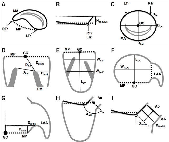
Figure 1. Schematic illustration of mitral valvular complex geometrical measurements. A) - C) Mitral annulus. D) Papillary muscles. E) Left ventricle. F) Left atrium. G) Left atrial appendage. H) & I) Left ventricular outflow tract. AA: aortic annulus; AAM: aorto-mitral angle; Ao: aorta; DAM: aorto-mural diameter; Daxial: axial distance to ostium of LAA; DCC: intercommissural diameter; DGC: papillary muscle head to GC distance; DMASE: mitral annulus to septal endocardium distance; Dplane: papillary muscle head to mitral plane distance; DPM: distance between papillary muscle heads; Dradial: radial distance to ostium of LAA; DTr: inter-trigone distance; DTrAA: trigone to aortic annulus distance; Dwall: wall to papillary muscle head distance; GC: geometrical centre of mitral annulus; Hannulus: height of mitral annulus; LAA: left atrial appendage; LLA: left atrium long-axis diameter; LLV: left ventricle length; LTr: left trigone; MA: mitral annulus; MP: mitral annulus plane; RTr: right trigone; W1/2LA: width of left atrium at half LLA; W1/2LV: width of left ventricle at half LLV; WPM: left ventricle width at level of papillary muscle heads
The aorto-mitral angle was defined as the angle subtended by the mitral and aortic valve annulus plane. We also measured the distance between each fibrous trigone and the aortic annulus plane –defined as the plane uniting the nadirs of each aortic leaflet. The distance between the mitral annulus and the septal endocardium was also recorded. Figure 1H and Figure 1I illustrate these measurements.
TRANSCATHETER MITRAL VALVE DEVICE LANDING ZONE
Transcatheter mitral valve replacement devices will probably extend into the regions of the ventricular and atrial cavities immediately adjacent to the mitral annulus. To characterise this zone, splines were drawn to outline the endocardial border at 5 mm intervals on the atrial and ventricular aspects of the mitral annulus. A total of eight regions of interest were drawn at 5, 10, 15, and 20 mm above and below the mitral annulus. The area, perimeter, aorto-mural and intercommissural diameters of these regions were recorded.
META-ANALYSIS OF STUDIES REPORTING MEASUREMENTS IN PATIENTS WITHOUT MITRAL REGURGITATION
A meta-analysis of previously published studies reporting measurements in patients without MR was performed to enable comparison of mitral valvular complex geometrical measurements between patients with and without FMR. This was necessary since the subject population from the PTOLEMY-2 trial did not include patients without MR. Studies performed in adults using computed tomography, echocardiography, and magnetic resonance imaging, as well as post mortem anatomical studies were screened for inclusion by a single observer. The criteria for inclusion were as follows: reporting of measurements equivalent to those performed in the current study and reporting of measurements without normalisation.
STATISTICAL ANALYSIS
The statistical analysis was performed using MATLAB Release 2013a (MathWorks, Natick, MA, USA). Every measurement from each subject was averaged between two independent observers. For geometrical measurements in diastole and systole, the mean and the standard deviation, as well as the median, first quartile, and third quartile were calculated. A paired-samples analysis was conducted to study dynamic variations between systole and diastole in 17 patients for whom images were available in both of these cardiac phases. Confidence intervals were computed using the bias corrected and accelerated percentile bootstrap method with 2,000 samples. For the meta-analysis of studies in patients without MR, the measurements were combined using the standard methodology7.
Results
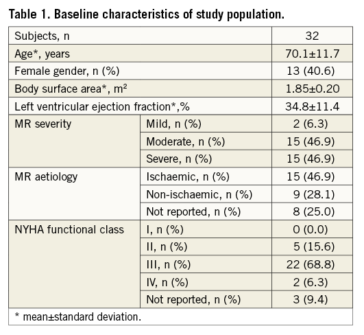
The baseline characteristics of the 32 patients are presented in Table 1. The average age was 70.1 years old, 40.6% of patients were female, and most patients suffered from left ventricular systolic dysfunction with an ejection fraction of 34.8%. Equal numbers of patients with moderate and severe FMR were included in the study.
MITRAL VALVULAR COMPLEX GEOMETRY
MITRAL ANNULUS
The mitral annulus was nearly circular with the intercommissural diameter being less than 3 mm larger than the aorto-mural diameter (diastole: 41.5 mm intercommissural vs. 40.0 mm aorto-mural; systole: 41.5 mm intercommissural vs. 38.7 mm aorto-mural) (Table 2). For all annulus measurements, the standard deviation was generally well above 10%, which demonstrated a relatively large amount of inter-patient variability. The annulus contracted slightly during systole (Figure 2). The dynamic changes of the annulus during the cardiac cycle were of relatively low amplitude –less than 2%– and were greater along the aorto-mural direction. Small statistically significant dynamic variations were observed for the aorto-mural diameter, the projected perimeter, and the annulus height.
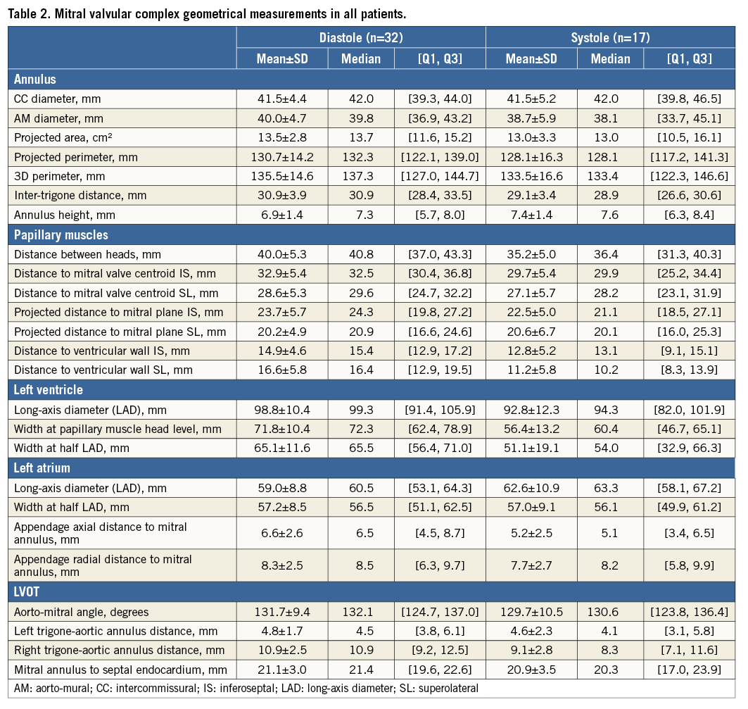
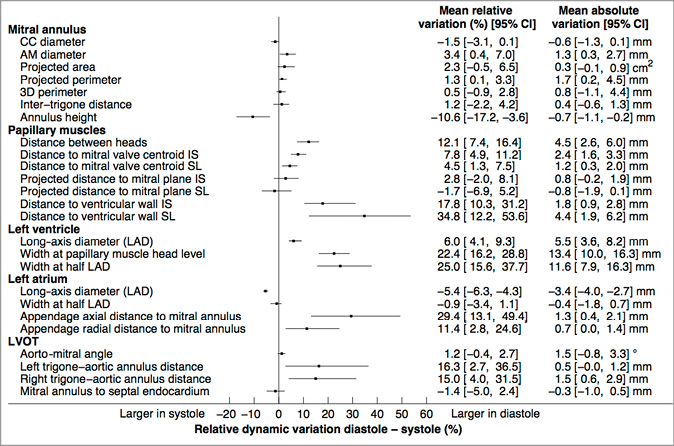
Figure 2. Paired-sample analysis of cardiac cycle dynamic variations in the mitral valvular complex geometrical measurements. 3D: tridimensional; AM: aorto-mural; CC: intercommissural; IA: inferoanterior; LAD: long-axis diameter; 95% CI: 95% confidence interval; SP: superoposterior
PAPILLARY MUSCLES
The papillary muscle heads were on average more than 20 mm below the mitral annulus plane and more than 27 mm from the mitral annulus centroid (Table 2). There was, however, substantial inter-subject variability in these measurements, with standard deviations of 5 to 6 mm. The projected distance between the papillary muscle head and the mitral plane varied by less than 1.2 mm (4.5%) between systole and diastole, which was not statistically significant.
LEFT VENTRICLE
The width of the left ventricle was on average greater at the level of the papillary muscle heads than midway between the mitral annulus geometrical centre and the apex (Table 2).
LEFT ATRIUM
The left atrial width was nearly equal to the long-axis diameter (Table 2). The atrial contraction manifested itself during diastole by a 5% reduction in the long-axis diameter and a mostly constant width (Figure 2). The ostium of the left atrial appendage was further from the mitral annulus during diastole than during systole in both the radial and axial directions.
LVOT
Several LVOT measurements are noteworthy. The aorto-mitral angle was approximately 131° on average but varied considerably between patients with a standard variation of approximately 10° (Table 2). The angle varied slightly but not significantly during systole (Figure 2). The right trigone was approximately twice as far as the left trigone from the aortic valve annulus plane (10.9 mm vs. 4.8 mm in diastole and 9.1 mm vs. 4.6 mm in systole). The trigone to aortic annulus distances were significantly greater during diastole (Figure 2).
TRANSCATHETER MITRAL VALVE DEVICE LANDING ZONE GEOMETRY
The perivalvular landing zones of transcatheter prostheses were evaluated up to 20 mm away from the mitral annulus plane on its atrial and ventricular aspects (Figure 3). The aorto-mural diameter, intercommissural diameter, perimeter and surface area are smaller in systole than in diastole in the left ventricle. In the left atrium, these measurements are larger in diastole. Overall, the majority of measurements on the atrial aspect of the valve do not demonstrate a significant dynamic variation between systole and diastole (Figure 3). This also holds true for the measurements of the mitral annulus, presented at distance 0 mm.
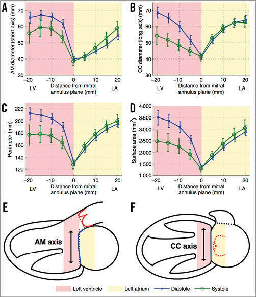
Figure 3. Transcatheter mitral valve device landing zone dynamic geometrical measurements. Each plot (A-D) shows a different measurement of the regions of interest drawn at the endocardial border in double-oblique planes parallel to the mitral annulus plane. The measurements at distance 0 mm represent the mitral annulus projected measurements. The error bars indicate 95% confidence intervals. A) Aorto-mural (AM) diameter. B) Intercommissural (CC) diameter. C) Perimeter. D) Surface area. E) & F) Schematic representation of the ventricular and atrial cavities. LA: left atrium; LV: left ventricle
META-ANALYSIS OF STUDIES REPORTING MEASUREMENTS IN PATIENTS WITHOUT MITRAL REGURGITATION
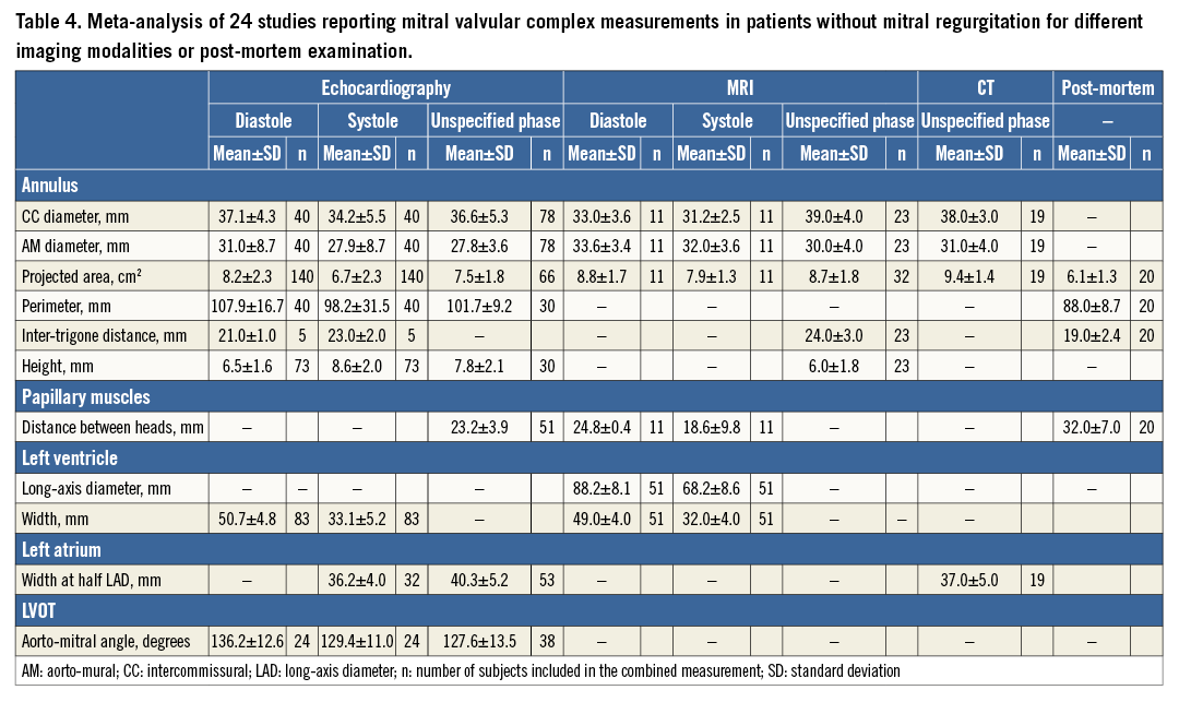
From a total of 238 studies screened, 24 studies fulfilled the inclusion criteria8-31. The results are presented in Table 3 and are divided by imaging modality in Table 4. Of the 25 measurements of the mitral valvular complex described in the current study, 11 measurements had previously been published for patients without MR. We classified measurements into systole or diastole if the cardiac phase was specified.
Discussion
MITRAL VALVULAR COMPLEX GEOMETRICAL CHANGES IN FMR
FMR occurs as a result of left ventricular dysfunction following an ischaemic or non-ischaemic injury to cardiac myocytes. In affected patients, a series of changes occurs in the dimensions and dynamics of the mitral valvular complex4, most of which are reflected in the measurements presented in this study.
The mitral annulus increases in size (Figure 2, Table 2, Table 4) and systolic contraction is reduced, which agrees with previous studies11,13,17-19,24,29,32,33. The annulus also becomes more circular in patients with MR and its height is slightly reduced. This deformation is believed to contribute to the pathophysiology of FMR11,33.
Papillary muscles become misaligned in FMR. We found a large increase in the distance between papillary muscles, which is attributable to the pathological changes in the left ventricular cavity. The misalignment increases the tethering force brought to bear on the mitral valve leaflets. The resulting leaflet tenting has been shown to be a major pathophysiologic mechanism in FMR24,30. We observed that the left ventricular cavity dilates and assumes a more spherical shape in FMR, which is consistent with previous studies11,14,25,26. These changes are considered to be a strong predictor of the severity of FMR. We demonstrated a large increase in the size of the left atrium in FMR. This change is consistent with previously published literature12,14,20.
The aorto-mitral angle showed only a small, non-significant dynamic change in FMR patients, while this angle varied considerably more in patients without MR27. The systolic angle was mostly preserved but the diastolic angle was less in FMR.
IMPLICATIONS FOR TRANSCATHETER MITRAL VALVE DESIGN AND PATIENT SELECTION
This study is the first to evaluate the mitral valvular complex focusing on measurements relevant for transcatheter mitral valve replacement in patients with FMR. Most proposed devices are mounted on a catheter, inserted across the mitral valve and then deployed. The mitral annular dimensions are critical for the design of prostheses. We demonstrated that, in patients with FMR, the mitral annulus is approximately symmetrical between its two major axes. The annulus also contracts less than 2% in systole. This may alleviate concerns that contractions of the mitral annulus may cause excessive stress on the prosthetic valve frame. Nonetheless, we showed that the region of the left ventricle immediately below the mitral annulus is highly dynamic, which may potentially cause substantial stress on a device. Conversely, a rigid ventricular device may be prone to injure the endocardial surface of the cavity.
The frame of transcatheter valve implants may protrude on either aspect of the mitral annulus. In the ventricular cavity, papillary muscles can represent an obstacle to the deployment of transcatheter devices. We demonstrated here that the projected distance between the mitral plane and the heads of papillary muscles –in other words, the axial obstacle-free zone for the prosthesis deployment– is approximately constant during the cardiac cycle.
Prosthetic structures extend radially outward to anchor the device within its landing zone and to prevent perivalvular leaks. We described the space available for the deployment of such anchoring structures up to 20 mm above and below the mitral annulus plane. We showed that the atrium is considerably less dynamic than the ventricle and may thus constitute a more adequate region for hosting a transcatheter device.
On the ventricular aspect, the left ventricular outflow tract is in close proximity to the mitral annulus. Thus, there exists a potential for outflow tract obstruction in some circumstances (Figure 4): 1) an excessively acute angle between the mitral plane and the aortic annulus, 2) small mitral annulus to septal endocardium distance, 3) excessive protrusion of the device in the left ventricular cavity, or 4) excessive flaring of the device at the ventricular end. Furthermore, an implant may directly impinge on the aortic valve; prosthetic valves may have anchoring structures that protrude along the LVOT and directly abut against the aortic valve leaflets. A reduced trigone to aortic annulus distance –demonstrating the proximity of the aortic valve along the LVOT– may pose an increased risk of impingement. Finally, the aorto-mitral curtain that separates the aortic valve from the left atrium is a thin and relatively compliant structure. Thus, a device deployed within the left atrium may cause a deformation of the aorto-mitral curtain and interfere with the geometry of the aortic root. Hypothetically, a direct impingement on the aortic valve may result in aortic regurgitation.
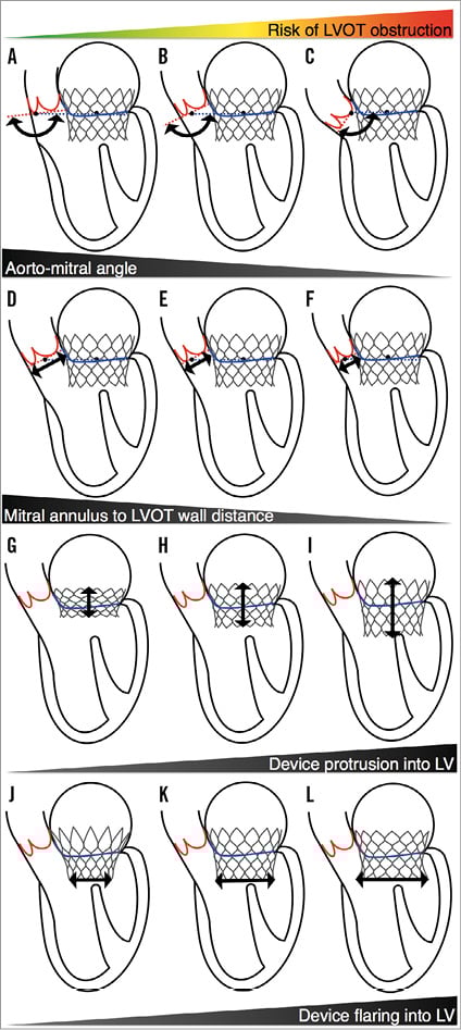
Figure 4. Potential mechanisms of left ventricular outflow tract obstruction in transcatheter mitral valve replacement. A-C) Increasingly acute angle between the mitral plane and the aortic annulus. D-F) Decreasing mitral annulus to septal endocardium distance. G-I) Increasing protrusion of the device in the left ventricular cavity. J-L) Increasing flaring of the device in the left ventricle. LV: left ventricle; LVOT: left ventricular outflow tract
LIMITATIONS
The scans were obtained from 15 different institutions, each of which used different CT scanner models. This variability made the systematic selection of an end-systolic and end-diastolic phase impossible. The temporal resolution of MSCT scans is also limited. The results may thus underestimate the dynamics of the structures studied. Also, the number of patients included in the study was limited.
Conclusion
The mitral annulus is on average larger in size, more circular, and less dynamic in patients with FMR versus those without MR. The obstacle-free zone below the mitral annulus is relatively constant during the cardiac cycle. The aorto-mitral angle, which may predict the risk of left ventricular outflow tract obstruction after transcatheter device implantation, varies considerably among patients.
| Impact on daily practice Transcatheter mitral valve replacement is a developing treatment modality for inoperable patients with severe symptomatic mitral regurgitation. This article provides a reference range for the size of cardiac structures in the patient population targeted by these interventions. |
Conflict of interest statement
P. Thériault-Lauzier is a consultant for HighLife Medical. G. Martucci is a proctor for Medtronic. R. Lange is a consultant for Medtronic. N. Piazza is a proctor and consultant for Medtronic. The other authors have no conflicts of interest to declare.