
Abstract
Aims: Transcatheter mitral valve replacement (TMVR) is an emerging technology with the potential to treat patients with severe mitral regurgitation at excessive risk for surgical mitral valve surgery. Multimodality imaging of the mitral valvular complex and surrounding structures will be an important component for patient selection for TMVR. Our aim was to describe and evaluate a systematic multi-slice computed tomography (MSCT) image analysis methodology that provides measurements relevant for transcatheter mitral valve replacement.
Methods and results: A systematic step-by-step measurement methodology is described for structures of the mitral valvular complex including: the mitral valve annulus, left ventricle, left atrium, papillary muscles and left ventricular outflow tract. To evaluate reproducibility, two observers applied this methodology to a retrospective series of 49 cardiac MSCT scans in patients with heart failure and significant mitral regurgitation. For each of 25 geometrical metrics, we evaluated inter-observer difference and intra-class correlation. The inter-observer difference was below 10% and the intra-class correlation was above 0.81 for measurements of critical importance in the sizing of TMVR devices: the mitral valve annulus diameters, area, perimeter, the inter-trigone distance, and the aorto-mitral angle.
Conclusions: MSCT can provide measurements that are important for patient selection and sizing of TMVR devices. These measurements have excellent inter-observer reproducibility in patients with functional mitral regurgitation.
Abbreviations
LVOT: left ventricular outflow tract
MPR: multi-planar reconstruction
MSCT: multi-slice computed tomography
TAVR: transcatheter aortic valve replacement
TMVR: transcatheter mitral valve replacement
Introduction
Following the successes of transcatheter aortic valve replacement (TAVR), transcatheter mitral valve replacement (TMVR) has emerged as a promising therapeutic option for patients with mitral regurgitation who are at excessive surgical risk1,2. Novel transcatheter devices aim to replace the dysfunctional mitral valve without the need for open heart surgery.
The anatomy of the mitral valve is more complex than that of the aortic valve. One has to appreciate the anatomical features that are in close proximity to the mitral valve when planning transcatheter mitral valve therapy. The anatomy of the mitral valve is further complicated by its saddle-shaped annulus that undergoes a series of dynamic changes during the cardiac cycle.
Given the inherent anatomical complexity of the mitral valvular complex, pre-procedural screening is likely to be of considerable importance for patient and device selection during TMVR. Echocardiography remains the gold standard imaging modality, allowing quantitative and qualitative anatomical assessment3. However, multi-slice computed tomography (MSCT) has emerged as the imaging modality of choice for assessment of the aortic valvular complex in the setting of TAVR4. Compared to echocardiography, MSCT affords more accurate measurements of the aortic annulus and, when applied to transcatheter heart valve sizing, results in superior procedural and clinical outcomes5,6. MSCT has been investigated to assess the function and anatomy of the mitral valve. In the context of mitral regurgitation, MSCT can be used to determine the disease aetiology7,8, to quantify the severity9,10, to describe changes in the geometry of the valvular complex11,12, and to diagnose mitral valve prolapse13-15. However, a detailed methodology for analysing the geometry of the mitral valvular complex specifically for the purposes of TMVR has not yet been described.
Herein, we present a systematic approach for the interrogation of an MSCT data set for potential TMVR recipients. This measurement methodology was applied to patients with significant mitral regurgitation to study inter-observer reliability.
Methods
MSCT IMAGE ACQUISITION PROTOCOL
MSCT imaging protocols have been described for patients undergoing TAVR4,16,17. Similar guidelines can be followed when designing an acquisition protocol for TMVR. The heart as well as access sites should be scanned. The cardiac acquisition should be performed using ECG gating on a scanner with at least 64 detector rows, and a slice thickness of less than 1 mm should be selected. The mitral valvular complex being a dynamic structure, multiphase imaging should be used to obtain images during systole and diastole. Retrospective gating is suggested for more flexibility in image reconstruction, which is particularly important in patients with arrhythmias. Supplemental beta-blockade is not generally necessary; at heart rates above 70 bpm, multi-segment reconstruction should be used. The dose of ionising radiation imparted to patients should be minimised but not at the expense of image quality. Indeed, potential patients for TMVR are likely to be elderly and to suffer from multiple comorbidities, which therefore mitigates the benefit of dose reduction. The tube potential should be selected as 100 kVp in patients weighing less than 90 kg or with a body mass index less than 30 kg/m2, and otherwise should be selected as 120 kVp. Tube current is dependent on specific scanners. Intravenous iodinated contrast agent at a rate of 3-5 mL/s should be injected to visualise cardiac and vascular structures. The timing of the contrast agent injection can be done via a test bolus or via bolus triggering. The duration of the injection should be such that the left atrium, left ventricle, and ascending aorta are opacified.
MSCT DATA SET ANALYSIS: MEASUREMENT METHODOLOGY
The methodology proposed in this article was developed using 3mensio Structural Heart 6.1 (Pie Medical Imaging BV, Maastricht, The Netherlands). This software package offers a dedicated workflow for mitral valve analysis18. However, the methodology should be general enough to be applicable to any software providing double-oblique multi-planar reconstructions (MPR).
The mitral valvular complex comprises the left atrium, mitral annulus, valve leaflets, chordae tendineae, papillary muscles, and the left ventricular cavity. For the purposes of this manuscript, these structures are described according to their anatomical position rather than the more traditional Valentine position. Attitudinal anatomy assumes the subject is facing the observer and standing upright19.
Mitral valve annulus
Similar to transcatheter aortic valve implantation (TAVI), assessment of the valve annular dimensions is of critical importance for valve sizing in the setting of TMVR. However, unlike the aortic valve, the mitral valve is rarely calcified. Accurate and precise sizing of the device may reduce the risk of excessive oversizing, which may result in annular rupture or left ventricular outflow tract (LVOT) obstruction with a suboptimal cardiac output. It may also mitigate complications of insufficient oversizing that may result in paravalvular leak or prosthesis embolisation.
Two perpendicular diameters of the mitral valve are measured: the aorto-mural and intercommissural diameters. The aorto-mural diameter is analogous to the anterioposterior diameter defined in echocardiography. To ensure repeatability of measurements, the aorto-mural diameter of the mitral annulus is measured along the line that bisects the aortic root at the level of the mitral annulus (Figure 1). This line also crosses the geometrical centre of the annulus. The intercommissural diameter is measured in the direction perpendicular to the aorto-mural diameter and passing through the annular geometrical centre. Note that while the intercommissural diameter is often parallel with the coaptation line of the leaflets, it does not represent the leaflet apposition length. The tridimensional annulus is projected onto its best-fit plane before the annular area and perimeter are measured.
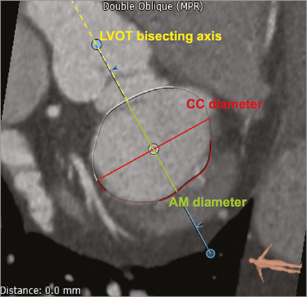
Figure 1. Mitral annular dimensions. The aorto-mural (AM) and intercommissural (CC) diameters on a short-axis MPR. The oval annulus is displayed. The aorto-mural diameter is measured parallel to the LVOT axis, while the intercommissural diameter is perpendicular.
The accuracy and reproducibility of the measurements described above depend on consistent selection of the mitral annulus. We propose the following methodology:
Step 1: A double oblique MPR is computed such that two views are displayed: (1) a long-axis slice with a plane that passes through the left ventricular apex and the mitral valve centre point, and (2) a short-axis view orthogonal to the long axis.
Step 2: The user can rotate the long-axis plane around the mitral-valve-to-apex axis in order to choose a view to begin selecting the annulus. We suggest selecting a plane in a region where the mitral annular hinge point is easily discernible, e.g., the left fibrous trigone.
Step 3: The annulus contour is defined by successively selecting 10 to 20 closed spline control points in the long-axis oblique MPR. The long-axis plane is rotated incrementally after each control point is positioned. The annulus-leaflet attachment point may have a different morphology depending on the region of the annulus (fibrous or muscular) and on the physical properties of the leaflet. These factors impact on the annulus selection procedure. Therefore, we describe the method in each region separately.
Muscular annular region: In this region, the selection is done in the long-axis view. The four annular sections shown in Figure 2 demonstrate different situations encountered. In all cases, we extrapolate the left ventricle and left atrium endocardial borders over the leaflet and select the point at the intersection of the two lines. Because of the increased curvature of the atrial cavity, the point of attachment is often selected on the atrial aspect of thickened or calcified leaflets. This accounts for the observation that annular calcification is typically encountered beneath the surface of the mitral leaflets20.
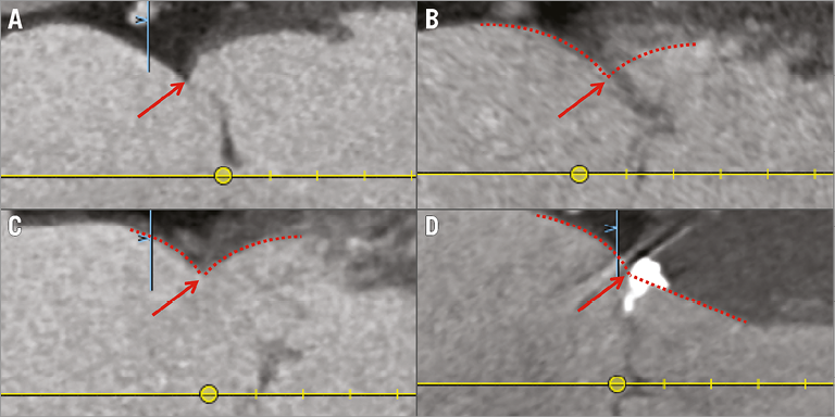
Figure 2. Mitral annulus: muscular region. Different types of annulus-leaflet attachments in the muscular annular region in the long-axis view. The types are: A) visible leaflet with clearly defined attachment; B) non-visible leaflet with clearly defined attachment; C) visible leaflet with thickened attachment; D) visible leaflet with calcified attachment. The annulus-leaflet attachment is selected at the intersection of the extrapolation of the left ventricle and LA endocardial borders.
Fibrous annular region: The method described for the muscular annular region cannot be readily applied in the region of the aorto-mitral curtain. In this region, the annulus is selected using the short-axis view. For planes intersecting the annulus (Figure 3), there is a difference in attenuation coefficient and thickness between the annulus and extensions from the fibrous trigones. Therefore, the leaflet is defined as the central lower attenuation portion of the curtain. The annulus point is therefore selected at the interface between those two regions.
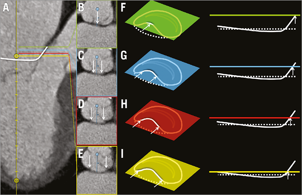
Figure 3. Mitral annulus: fibrous region. Annular-leaflet attachments in the fibrous (aortic) annular region. In panel A, the long-axis MPR shows sections through the annulus at four levels. Panels B to E represent short-axis sections through the annulus at regular intervals from the base-to-apex direction. In panels F to I, schematic representations of the image planes in B to E are shown relative to the mitral annulus in a perspective view and in a side view. In all cases, arrows indicate points of the annulus intersected by the image plane.
Papillary muscles
Papillary muscles may present physical obstacles within the left ventricle that limit the potential space for prosthesis deployment. The number of papillary muscles and their relative distance from the mitral annulus may have implications for certain TMVR prototypes.
This analysis focuses on the muscular projections that extend closest to the plane of the annulus, as these are the most likely to have an impact on TMVR devices. Measurements are performed for the papillary muscle head closest to the mitral annulus for each of the inferoseptal (IS) and superolateral (SL) divisions of the chordopapillary support21. After selection of the two muscle heads, the tridimensional linear distance between the heads is measured (Figure 4). The tridimensional linear distance between the geometrical centre and each papillary muscle head, as well as the perpendicular distance between the annulus best-fit plane and each papillary muscle head are measured. Finally, the distance between the papillary muscle head and its associated endocardial wall is measured perpendicular to the axis between the geometrical centre and the left ventricular apex.
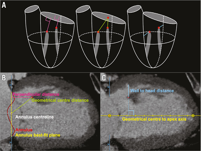
Figure 4. Papillary muscle evaluation. A) Proposed papillary muscle measurements in three dimensions. Panels B and C illustrate the measurements performed on CT images.
In order to ensure reproducible measurements, we propose the following methodology for the selection of the muscle heads:
Step 1: The selection of the papillary muscle heads is performed relative to the mitral annulus. The mitral annulus must first be created as described in the previous section.
Step 2: The muscle heads are selected in short-axis view. The distance between the plane of the MPR and the annulus is gradually increased until a papillary muscle appears within the left ventricular cavity.
Step 3: The MPR short-axis plane is set at the distance where only the tip of the papillary muscle is visible. A marker is placed on the papillary muscle head in the short-axis view.
Left ventricle
Transcatheter valve implantation at the level of the mitral annulus gives rise to potential interactions between the prosthesis and the anatomical structures on the atrial and/or ventricular side of the annulus. Therefore, accurate assessment of the “structure-free space” or “landing zone” (long and short axis, area, and perimeter) is of importance for TMVR. The anatomical relationship of the mitral valve and the LVOT suggests that there is the potential for LVOT obstruction if a rigid oversized prosthesis is implanted within the mitral annulus. Furthermore, tethering of the chordae in mitral regurgitation could reduce the ventricle wall to annulus distance, thus increasing the risk of LVOT obstruction and systolic anterior motion of the mitral valve.
The left ventricle measurements aim to describe the shape of the cavity and, most importantly, define in detail the region just beneath the mitral annulus, including the LVOT. We measure the left ventricle long-axis diameter, which is defined as the distance between the mitral annulus geometrical centre and the left ventricular apex (Figure 5). The width of the left ventricle is measured at two specific distances from the geometrical centre: (1) at 50% of the left ventricle long-axis diameter; and (2) at a point halfway between the papillary muscle heads. In both cases, papillary muscle tissue is considered to be part of the left ventricular cavity.
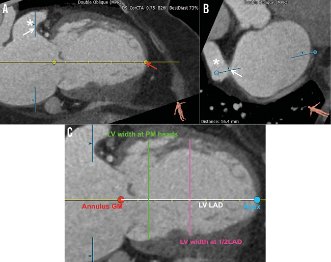
Figure 5. Left ventricular assessment. A) & B) Illustration of the long-axis MPR selected for measurements on the left ventricle (LV). The left atrial appendage is indicated by the star (*). The red arrow indicates the LV apex. The white arrows indicate the anterior aspect of the appendage used as a landmark in the selection of the long-axis view. The MPR planes are indicated by the light blue lines. C) Measurements of the LV in long-axis view. The LV long-axis diameter (LV LAD) and the LV width at half LAD are pictured.
The left ventricular measurements are performed in a long-axis MPR whose plane bisects the left atrial appendage. This view is selected as follows:
Step 1: The mitral annulus is first selected using a curved spline as described above.
Step 2: The left ventricular axis is adjusted such that the left ventricular apex marker is placed at the point of the endocardium that is most distal from the annulus geometrical centre (Figure 5).
Step 3: The long-axis plane is then rotated such that it bisects the left atrial appendage as shown by the arrow in Figure 5. The measurements are pre-formed in the view thus obtained.
The region just beneath the mitral annulus is of particular interest since it may constitute a landing zone for TMVR prostheses. In a short-axis MPR that is parallel to the annulus best-fit plane, we draw a region of interest that outlines the endocardial border (Figure 6). For this analysis, the papillary muscles and trabeculae carneae are considered to be part of the ventricular wall. The short- and long-axis diameters (parallel to the annulus aorto-mural and intercommissural directions), the area, and the perimeter are recorded for each region of interest. These measurements are repeated at 5 mm intervals below the mitral annulus up to 20 mm.
To assess the relationship between the mitral annulus and the LVOT, several measurements are of particular interest in the context of TMVR. The aorto-mitral angle, which lies between the axis of the LVOT and the centreline of the mitral annulus, is noted (Figure 6). The distance between the medial aspect of the mitral annulus and the septal aspect of the LVOT is measured. Then, the positions of the right and left fibrous trigones are marked and the aorto-trigonal distance - defined as the perpendicular distance from each trigone to the aortic valve annulus - is recorded (Figure 7). It quantifies the distance along the LVOT into which a TMVR device could extend before potentially interacting with the aortic valve leaflets.
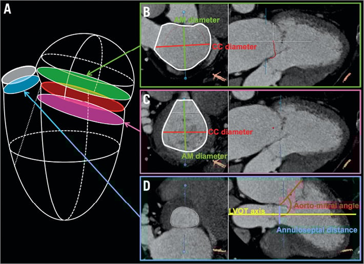
Figure 6. Left atrial, ventricular, and outflow tract dimensions. A) Anatomical location of the MPR planes for the left atrium (B), the left ventricle (C), and the left ventricular outflow tract (D).
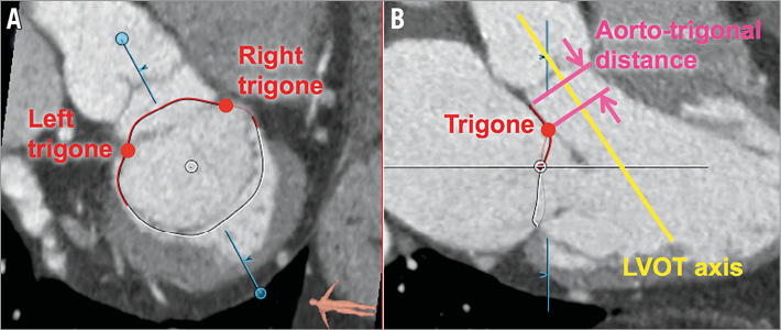
Figure 7. The fibrous trigones and aorto-trigonal distance. A) Short-axis view of the right and left fibrous trigones. B) Long-axis view of the trigones and illustration of the aorto-trigonal distance.
Left atrium
Transcatheter devices may be delivered using transseptal, transatrial or transapical approaches. The first two methods require direct interaction with the left atrium. MSCT can be used to examine the configuration of pulmonary veins and the anatomy of the atrial septum qualitatively. Furthermore, MSCT can also be used to quantify the geometry of the region. The left atrium measurements are similar to those described for the left ventricle, and aim to characterise the shape of the left atrium and carefully assess the region immediately above the mitral annulus. The left atrium long-axis diameter is measured between the annulus geometrical centre and the posterior atrial wall in the direction of the annulus centreline (Figure 8). The left atrium width at 50% of the long-axis diameter is measured perpendicular to the annulus centreline, midway between the annulus geometrical centre and the posterior atrial wall. The left atrial appendage and the pulmonary veins are excluded from the measurements. The distance between the ostium of the left atrial appendage and the mitral annulus is measured in both axial and radial directions (Figure 8). As with the left ventricle, left atrium polygons are drawn at 5 mm increments from the mitral annular plane up to a maximum of 20 mm. The short- and long-axis diameters, area and perimeter of the polygons are recorded (Figure 6). These measurements, together with their annular and left ventricular counterparts, provide information about potential landing zones for prostheses.
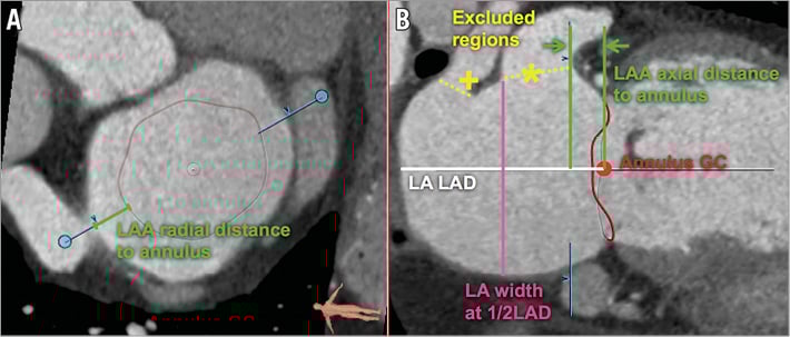
Figure 8. Left atrium assessment. Measurements of the LA in the short-axis (A) and long-axis (B) views. Note, the left atrial appendage (*) and a pulmonary vein (+) are excluded.
STUDY POPULATION
In this article, we performed a retrospective analysis in subjects recruited from the PTOLEMY-2 (NCT00787293) and PTOLEMY2Canada (NCT00815386) clinical trials of the Viacor percutaneous transvenous mitral annuloplasty system (Viacor, Inc., Wilmington, MA, USA) in 15 European and Canadian centres. Written consent was obtained from patients and the study was conducted with the approval of institutional ethics review boards. The trial was conducted to evaluate the implantation of this device in patients in heart failure with functional mitral regurgitation. The PTOLEMY-2 and PTOLEMY2Canada studies were suspended due to a high rate of complications. At the conclusion of the studies, the MSCT data sets were made available for research purposes to collaborating investigators, including authors of this manuscript. Preoperative MSCT images were available in 32 patients: 15 scans included only a diastolic phase and 17 scans included both a systolic and a diastolic phase.
STATISTICAL ANALYSIS
Two independent observers measured 25 different geometrical properties of the mitral valve apparatus using the above-described methodology. The inter-observer agreement was studied using the intra-class correlation and the coefficient of variation, for all scans irrespective of cardiac phase. Thus, 49 individual samples were used from 17 systolic scans and 32 diastolic scans. The statistical analysis was performed using MATLAB R2013a (MathWorks, Natick, MA, USA). Confidence intervals were computed using the bias corrected and accelerated percentile bootstrap method with 2,000 samples.
Results and discussion
The baseline characteristics of the 32 patients are presented in Table 1. The average age was 70.1 years old, 40.6% of patients were female, and most patients suffered from left ventricular systolic dysfunction with an ejection fraction of 34.8%. Thirty of the 32 patients had moderate or severe mitral regurgitation, while two patients had mild mitral regurgitation.
The variability between the two observers was quantified using the inter-observer difference and the intra-class correlation (Table 2). The inter-observer difference was generally below 10%, except for the annulus height and the left atrial appendage distance to the mitral annulus. Both of these structures have a dimension of less than 10 mm and an absolute inter-observer difference approximately equal to the slice thickness. The intra-class correlation shows excellent inter-observer agreement for most measurements. The intra-class correlation is greater than 0.60 except for the annulus height with 0.31. This measurement is highly dependent on precise selection of the fibrous region of the mitral valve annulus.
We presented a detailed step-by-step methodology for analysing an MSCT data set for the purposes of TMVR. This information is of relevance for those involved in the design and development of these novel transcatheter devices, and will be of importance in determining patient suitability in the future. Previous literature on mitral valve MSCT focused on establishing diagnosis and characterising pathological states7-15,22. Furthermore, the measurement methodology and nomenclature are heterogeneous among different authors. The systematic methodology presented here has the potential to facilitate the comparison of studies and the communication of results.
MSCT has proven to be of considerable importance in the assessment of aortic annular diameters and valve sizing for patients undergoing TAVI5,6,23. Imaging techniques, such as two-dimensional transoesophageal echocardiography (2DTEE) and MSCT, provide complementary information on the anatomy and spatial relationships of the mitral valve24. While 2DTEE has a higher temporal resolution and enables assessment of blood flow, it remains a two-dimensional modality that may not provide accurate dimensions of complex tridimensional structures. MSCT offers temporally resolved volumetric imaging with high, nearly isotropic spatial resolution. Given the dynamic, non-planar geometry of the mitral annulus, it can be expected that MSCT may provide more accurate measurements than 2DTEE. As demonstrated here, MSCT has minimal operator dependence for the assessment of the mitral valve annulus. When coupled with a dedicated analysis software package, MSCT-derived measurements of the mitral valve have a low inter-observer variability relative to echocardiography. Accurate, standardised, tridimensional measurements of the mitral valve and its surrounding structures, as detailed in this manuscript, will be important for determining patient suitability for these complex structural heart interventions. We believe that, in the future, physicians involved in transcatheter treatment of the mitral valve will need to understand the value and limitations of tomographic measurements. The advantages of MSCT do not diminish the crucial role of 2DTEE for real-time intraoperative guidance of transcatheter procedures. Furthermore, advances in tridimensional transoesophageal echocardiography (3DTEE) may alleviate concerns regarding inter-observer agreement; in preliminary studies 3DTEE showed good agreement with MSCT25 and greater accuracy compared to 2DTEE26 for measurements of the mitral valvular complex.
All proposed TMVR devices are in active development with ongoing device iteration based on preclinical testing and in-depth imaging analysis of the mitral valve. To this end, the standardised method for MSCT analysis of the mitral valvular complex presented here and the application of the anatomical findings may assist valve design and development. An analysis of dynamic stresses and strains applied on these devices may eventually be performed based on MSCT images. Moreover, it is hoped that the continued use of MSCT in the evaluation of inoperable patients with severe mitral regurgitation will help to define anatomical inclusion or exclusion criteria for each device.
LIMITATIONS
A few limitations of the study presented here should be noted. This study does not provide a validation of the methodology based on gold standard anatomical measurements. Further work is necessary to address this issue. Overall, the number of CT scans included in the study was limited. However, we believe that the study was sufficiently well powered to study inter-observer variability. Furthermore, it is important to note that the results reported here depend on the expertise of the user as well as the appropriate CT protocol. For optimal images to be obtained, it is crucial that interventionalists communicate with the medical imaging specialist about the goals to be achieved with regard to contrast-to-noise ratio, temporal and spatial resolution.
The CT scan protocols used in this study were heterogeneous. While this can be perceived as a limitation, it can be hypothesised that the measurement methodology is robust with regard to CT protocol selection given the high inter-observer reliability. Data regarding heart rate and rhythm are not available for a large majority of the subjects included in this study. However, all patients were imaged using an ECG-gated protocol. Heart rate is important because of the limited temporal resolution of CT scanners; heart rhythm is of interest because an irregular rhythm, such as in atrial fibrillation, may lead to erroneous ECG gating and significant image artefacts in multi-segment reconstruction. Retrospective gating may help correct this limitation.
Conclusion
The advent of transcatheter mitral valve repair and replacement demands a detailed assessment of the mitral valvular complex. We present a comprehensive step-by-step approach to analysing an MSCT data set for the purposes of TMVR. We demonstrated that this methodology provides measurements of the mitral valve annulus with high intra-class correlation and low inter-observer variation.
| Impact on daily practice Transcatheter mitral valve replacement is a developing treatment modality, which will require highly accurate anatomical measurements of the mitral valvular complex for patient selection and device sizing. This article describes an analysis methodology that can be adopted by clinicians to provide such measurements in a reproducible manner. |
Acknowledgements
The authors would like to thank Luc Verstraeten from Pie Medical Imaging for his assistance with the analysis software.
Conflict of interest statement
P. Thériault-Lauzier is a consultant for HighLife Medical. G. Martucci is a proctor for Medtronic. R. Lange is a consultant for Medtronic. N. Piazza is a proctor and consultant for Medtronic. S. Windecker is a scientific advisory board member of Cardialysis BV. The other authors have no conflicts of interest to declare.