Transcatheter aortic valve implantation (TAVI) has been increasingly recognised as a viable therapeutic option in patients with severe aortic stenosis and at high risk for surgical valve replacement1. In order to obtain optimal results during TAVI, valve delivery should be performed under fluoroscopic guidance with three valve cusps aligned. The valve apparatus is, however, a three-dimensional (3-D) anatomic structure, which limits angiographic capabilities to find the ideal alignment between cusps properly. Different strategies to accomplish this key step during TAVI have been proposed: (1) an angiography-based approach, which would probably demand additional contrast volume, time and radiation exposure2; (2) a two-dimensional (2-D) computed tomography (CT) technique which, although it provides an explanation as to how to determine C-arm angulation, does not clearly specify how to obtain both cranial-caudal and lateral angulations of the C-arm3; and (3) a 3-D CT approach which requires the use of expensive software4. We propose a technique that enables the calculation of optimal C-arm angulations (i.e., cranial-caudal and lateral) pre-intervention, based on 2-D CT images utilising OsiriX imaging software (Pixmeo, Geneva, Switzerland), which is available online (http://www.osirix-viewer.com) free, as explained in two case examples (Figure 1, Figure 2 and Moving image 1-Moving image 3).
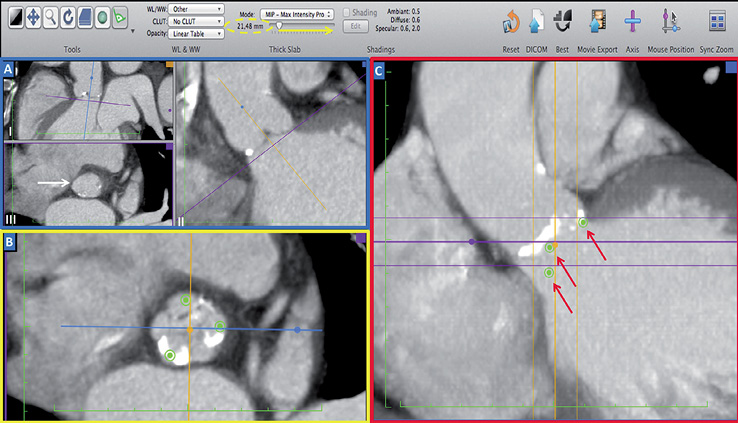
Figure 1. Identify aortic cusps and place points on them. Step 1: (A, blue square) by rotating the axis on sagittal (I) and coronal (II) views, one is able to obtain the perfect position of the aortic virtual ring with the nadir of the three cusps on the same plane (white arrow, double oblique view, III)5. Step 2: (B, yellow square) place a point on each cusp in double oblique view. Step 3: (C, red square) find the widest dimension of aortic root in the coronal view and increase slice thickness (using toolbar above, yellow arrow, yellow dashed oval) until the three points are shown in the coronal view (red arrows).
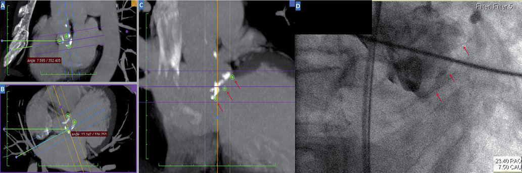
Figure 2. Obtaining cranial-caudal and lateral angles for C-arm positioning in the cathlab. Step 4: rotate both sagittal (A) and double oblique (B) axis tool until the three points appear aligned with equal distances between them in the coronal oblique view (C, red arrows). This is the optimal position of the aortic cusps. Step 5: finally, in order to determine C-arm angles, we use the sagittal oblique view (A) for cranial-caudal (i.e., ideal angle 7.59° caudal), and the double oblique view (B) for lateral positioning of C-arm (i.e., ideal angle 23.24° right). Note that angles formed below and above the horizontal reference line in the sagittal oblique view indicate, respectively, caudal and cranial angulations of the C-arm, while in the double oblique view they indicate right and left angulations, respectively. In the angiogram (D) one can depict optimal positioning of three valve cusps (red arrows) for valve implantation (angles shown in the right bottom part).
We speculate that our technique, which is easily accomplished with user-friendly, free, online available software, could ultimately save contrast injections, procedure time, and radiation exposure, while enabling optimal valve positioning4. Whether this approach could improve clinical outcomes in TAVI patients warrants further investigation.
Conflict of interest statement
The authors have no conflicts of interest to declare.
Online data supplement
Moving image 1. Representation of steps 1 and 2, as described in Figure 1.
Moving image 2. Representation of steps 3 and 4, as described in Figures 1 and 2.
Moving image 3. Representation of step 5, as described in Figure 2. Note that final angles obtained are different from the ones on Figure 2, as this is a different case.
Supplementary data
To read the full content of this article, please download the PDF.
Moving image 1. Representation of steps 1 and 2, as described in Figure 1.
Moving image 2. Representation of steps 3 and 4, as described in Figures 1 and 2.
Moving image 3. Representation of step 5, as described in Figure 2. Note that final angles obtained are different from the ones on Figure 2, as this is a different case.