Abstract
Aims: Precise visualisation of ductal morphology and adjacent vessels is crucial for accurate stent choice and placement during hybrid palliation of hypoplastic left heart syndrome (HLHS). We aimed to describe our initial experience with live three-dimensional reconstruction overlay derived from rotational angiography (RA) for ductal stenting in HLHS.
Methods and results: We carried out a retrospective review of ductal stenting in 18 newborns with HLHS, including six patients with 3D reconstruction overlay used to guide the intervention. The median age at the intervention was 20 days (range 13-31 days) and the median weight was 3.25 kg (range 3-4 kg). Eleven RA runs were performed, pre and post stent implantation in five patients and before the intervention in one patient. 3D reconstructions from all RA runs had sufficient image quality to allow stent placement without additional contrast injections. Comparison with 2D angiography-guided ductal stenting showed similar contrast usage, with the 2D angiography patients receiving a higher radiation dose.
Conclusions: Three-dimensional rotational angiography provides accurate visualisation of the ductal morphology and nearby structures. Three-dimensional reconstruction overlay with clear landing points enabled precise stent implantation with no additional contrast injections and lower radiation doses than conventional angiography in our patients.
Abbreviations
HLHS: hypoplastic left heart syndrome
LPA: left pulmonary artery
PA: pulmonary arteries
RA: rotational angiography
RAA: retrograde aortic arch
RPA: right pulmonary artery
2D: two-dimensional
3DRA: three-dimensional rotational angiography
Introduction
The hybrid approach is an alternative initial palliation for hypoplastic left heart syndrome (HLHS)1-6. It consists of bilateral pulmonary artery banding and ductal stent implantation. Precise visualisation of ductal morphology and adjacent vessels is crucial for accurate stent choice and placement. Limitations of traditional two-dimensional (2D) angiography, including structure foreshortening and overlay, lead to assumptions regarding, for instance, the origins of the retrograde aortic arch (RAA) and pulmonary arteries (PA). Three-dimensional rotational angiography (3DRA) has the potential to overcome some of these limitations and can facilitate interventional procedures by fusion of the 3D reconstruction with live fluoroscopy images7-10. This modality was initially developed in neurovascular interventional procedures, where it became the gold standard for visualisation of intracranial aneurysms11. Subsequently, 3DRA has been successfully validated for interventional radiology, electrophysiology, structural and congenital cardiac interventions12-16.
Despite a growing number of applications of 3DRA in the treatment of heart defects, reports focusing on 3D reconstruction-guided interventions in small patients are scarce. In this paper we describe our initial experience with 3D reconstruction overlay derived from 3DRA to guide ductal stenting during initial palliation of HLHS.
Material and methods
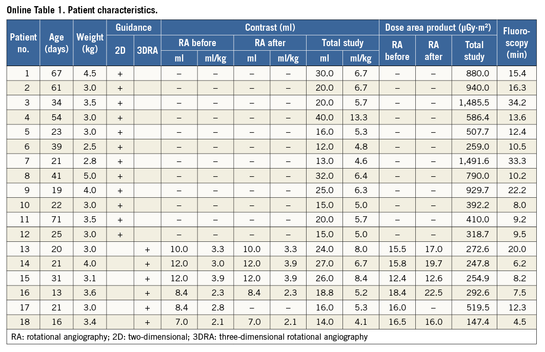
We performed a retrospective review of our catheterisation database to select all patients who had undergone ductal stent implantation with 3D reconstruction overlay. Patient characteristics included age, weight, diagnosis, contrast volume and dilution, and radiation dose. The time required for post-processing of raw 3D reconstruction was calculated by subtracting the time of the RA run from the first stored fluoroscopy sequence with 3D reconstruction overlay. Visualisation of ductal morphology, origin of the RAA, and PA was evaluated by the operating interventionist for rotational angiography (RA) and 3D reconstruction. Ductal diameters were compared in RA and 3D reconstruction and the accurateness of the overlay on fluoroscopy was evaluated. Patients who underwent ductal stenting with 2D angiography guidance on the same angiography system were selected for comparison of radiation dose, fluoroscopy time and contrast usage. This study was conducted with approval from our Institutional Review Board. The need for individual consent for data collection was waived.
PROCEDURAL DESCRIPTION
After transferring the patient to the catheterisation laboratory, the femoral vein was accessed and a short 6 Fr sheath was introduced17,18. A 4 Fr angiographic catheter was placed in the arterial duct for high-speed single-plane RA (Philips Allura Xper FD20; Philips Healthcare, Best, The Netherlands) with the duct positioned at the isocentre of rotation. A fully automated 4.1 second, 240˚ C-arm rotation from 120˚ right anterior oblique to 120˚ left anterior oblique was performed. Thirty frames per second were registered with a dose of 0.2 µGy per image (Moving image 1, Figure 1A). To limit motion artefact, the study was performed during an expiratory breath-hold. The injected contrast agent was Iomeron 400 (Bracco Imaging Deutschland GmbH, Konstanz, Germany). Initially we used full strength contrast and in the most recent patients we injected dilute contrast at a concentration of 60-70%. The delay between the beginning of the contrast injection and C-arm rotation was set at 0.5-1 seconds.
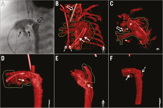
Figure 1. Rotational angiography and 3D reconstruction post-processing. A) Selected image from rotational angiography representing left lateral projection in conventional angiography shows origin of the left (black arrow) and right (dashed arrow) pulmonary artery. The origin of the retrograde aortic arch is overlaid with the distal part of the duct and the descending aorta (empty arrow). B) & C) Removal of irrelevant structures. The appearance of two catheter shafts (solid arrow) in the main pulmonary artery and splitting of the end of the venous central line (dashed arrows) reflect motion artefacts. The marker from the endotracheal tube provides another stable landmark which helps overlay alignment. D) Cutting out of the proximal main pulmonary artery. The origin of the left pulmonary artery (arrow) is retained as a marker for placement of the proximal end of the stent. E) The retrograde aortic arch was removed with the desired position of the distal end of the stent marked with a slice cut at the distal extent of the duct (dashed arrow). F) Reconstructed image after post-processing with marked proximal (solid arrow) and distal (dashed arrow) landing points for the stent.
An unprocessed rotational data set was available in less than 40 seconds for processing on a dedicated workstation (Interventional Tools; Philips Healthcare) by the same operator for all patients. The reconstructed images were optimised by manual windowing and segmentation (Figure 1B-Figure 1F). Minimal and maximal diameters as well as the length of the duct, from the origin of the left pulmonary artery (LPA) to the descending aorta beyond the isthmus, were measured on still images from RA and maximum intensity projections from 3D reconstruction. After highlighting the arterial duct with different image cutting tools, landing points for stent placement were marked at the level of the RAA origin and the LPA origin. The volume-rendered 3D reconstruction was merged with live fluoroscopic images using the automated software in a lateral projection for guidance of stent positioning and implantation (Figure 2A).
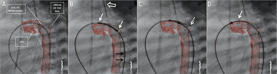
Figure 2. Fluoroscopy with live 3D reconstruction overlay. A) Post-processed 3D reconstruction overlaid on fluoroscopy. Alignment of the diagnostic catheter (black dashed line) placed across the duct with the curvature of the duct and the descending aorta confirms the accurateness of the overlay. All crucial points important for precise stent placement are clearly seen: origin of the retrograde aortic arch (RAA), left pulmonary artery (LPA) and ductal narrowing. B) Self-expanding nitinol stent positioned in the duct prior to deployment. A stiff wire required for system delivery distorts the anatomy and shifts the descending aorta towards the patient’s back which is reflected by wire (black arrows) and reconstruction misalignment. Accurate overlay of the endotracheal tube (white empty arrow) confirms proper overlay in the sagittal plane, and matched proximal and distal ends (white arrows) of the stent with the reconstruction confirm good overlay in the cranial plane. C) Stent is partially deployed with the distal end (dashed arrow) positioned at the level of the cut-out slice marking the origin of the RAA. D) After complete deployment, the stent covers the whole length of the duct with the proximal end (arrow) placed in the main pulmonary artery just proximal to the origin of the LPA.
A self-expanding Zilver Flex™ (Cook Medical, Dublin, Ireland) stent was chosen – 1 to 2 mm larger than the maximal ductal diameter and long enough to cover the whole length of the duct. The stent was advanced to the duct through a short femoral sheath and 3D reconstruction was used for positioning (Moving image 1, Figure 2B-Figure 2D). After implantation, a final 3DRA was performed to confirm stent position and the relationship with adjacent structures (Moving image 1, Figure 3).
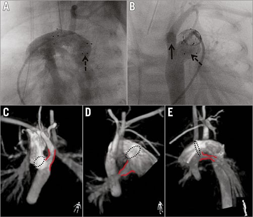
Figure 3. Final rotational angiography and 3D reconstruction presented with maximum intensity projection. A) Selected rotational angiography image corresponding to the left lateral projection in standard 2D angiography, showing the distal end of the stent (dashed arrow) protruding towards the descending aorta. B) Image corresponding to the posterior-anterior projection confirms the distal end (dashed arrow) of the stent within the distal ductal ampulla with unobstructed access (solid arrow) to the retrograde aortic arch. C), D) & E) Presentation of relationship between the ends (dashed circle) of the stent and nearby structures (red lines): retrograde aortic arch (C), right (D) and left (E) pulmonary artery. The human figure in the bottom right corner presents the perspective from which the structures are being evaluated. Non-standard planes, unavailable in 2D angiography, enable detailed assessment of the stent and the surrounding structures.
STATISTICAL ANALYSIS
Data analysis was performed using GraphPad InStat® software (GraphPad Software, Inc., San Diego, CA, USA). Due to the small numbers involved, non-parametric tools (Mann-Whitney test) were used for analysis. Data are presented as frequencies or medians with range, as appropriate. Correlation between 2D and 3DRA measurements was assessed using Spearman’s rank correlation and presented as R-values. The level of statistical significance was set at p≤0.05.
Results
Between March 2010 and March 2015 eighteen patients with HLHS or its variants underwent ductal stenting as part of “hybrid” first stage palliation. In the most recent six patients the intervention was guided with 3D reconstruction overlay. In this group, the median age at ductal stenting was 20 days (range 13-31 days) and the median weight 3.25 kg (range 3-4 kg). Ductal stenting was performed one day after bilateral pulmonary artery banding in four patients and two days after in two patients. One patient required inotropic support prior to transfer to the catheterisation laboratory and had successful balloon atrial septostomy immediately after ductal stenting.
ROTATIONAL ANGIOGRAPHY
Eleven RA runs were performed (Online Table 1). Five patients had RA pre and post stent implantation. One patient had RA pre stent deployment but became unstable during stenting, hence a quick hand contrast injection was performed to confirm final stent position.
Rotational angiography provided high-quality, diagnostic images of the arterial duct in all patients. The origin of the RAA, the aortic arch and the origin of the head and neck vessels could be clearly seen in all runs. Both pulmonary arteries were visualised in four patients. In one patient the angiographic catheter was placed too distally in the duct, resulting in visualisation of only the LPA. In another patient, the tight band placed on the LPA caused poor visualisation of its distal branches.
In the first three patients (six RA runs) undiluted contrast was used. The remaining patients (five RAs) received approximately 60-70% strength contrast. For the whole group, a median 10 ml (range 7-12 ml) of pure contrast per RA run was used which corresponded to 3 ml/kg (range 2.1-3.9 ml/kg). Median total contrast used for each study was 21.4 ml (range 14-27 ml) or 6 ml/kg (range 4.1-6 ml/kg). Administration of diluted contrast resulted in a lower single RA run (8.4 ml, range 7-8.4 ml; 2.3 ml/kg, range 2.1-2.8 ml/kg) and total investigation contrast dose (16 ml, range 14-18.8 ml; 5.2 ml/kg, range 4.1-5.3 ml/kg), without any discernible negative impact on image quality.
The median radiation dose for a single RA and combined RA in each patient and the complete study was 16 µGy·m² (range 12.4-22.5 µGy·m²), 32.5 µGy·m² (range 16-40.9 µGy·m²) and 263.7 µGy·m² (range 147.4-519.5 µGy·m²), respectively. Rotational angiography was responsible for a median of 13% (range 3-22%) of the total radiation dose for each procedure. The median fluoroscopy and total study times were 7.9 min (range 4.5-20 min) and 47.5 min (range 40-95 min), respectively.
The median percentage of the dose by RA of the total study was 86% of the entire contrast used during the procedure (range 52.5-100%). Excluding the previously mentioned patient who destabilised during the intervention and had final hand contrast injection, in one patient contrast was administered only for RA, with the remaining patients receiving small hand injections (range 2-5 ml) to position the angiographic catheter prior to the run.
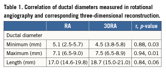
The minimum ductal diameter ranged from 2.5 to 5.7 mm (median 5.1 mm) and the maximum diameter from 6.5 to 9 mm (median 7.1 mm). The ductal length ranged from 14.6 to 19.8 mm (median 17 mm). The narrowest segment of the duct was at the pulmonary end in three, the mid portion in two and at the aortic end in one patient.
THREE-DIMENSIONAL RECONSTRUCTION
The median time to create a 3D reconstruction from the raw data set was 9.5 min (range 4-20 min). This time decreased steadily over the course of the six patients. A good reconstruction of the arterial duct and the RAA was available in all patients. Proximal pulmonary arteries were seen on 3D reconstruction in all but one patient, in whom the catheter was placed too distally and only the LPA could be visualised. In another patient, a tight LPA band precluded enough contrast flow to the distal branches, resulting in poor reconstruction. The image quality of 3D reconstruction was sufficient to allow stent positioning and deployment in all patients.
Minimum, maximum diameters and ductal length correlated with measurements taken on corresponding RA images (Table 1).
Passing the stiff wire and delivery system through the duct changed the alignment of the vessels to an extent in every patient (Figure 2B, Figure 2C). However, accurate overlay of the reconstructed duct on live fluoroscopy was achieved in all patients. During stent placement in three patients, the proximal end appeared to be shifted upwards towards the greater curvature when compared with the 3D reconstruction (Figure 2B). This had no effect on stent deployment and, once the stent was completely released, accurate alignment was seen in all patients.
DUCTAL STENTING
All but one patient received a single self-expanding stent. This single patient required two overlapping stents to cover the whole length of the duct. No additional contrast injections were required to position the stents or during stent deployment. Overall, 3D reconstruction guidance was applied successfully and without adverse effects for all stent implantations.
COMPARISON WITH 2D GUIDANCE
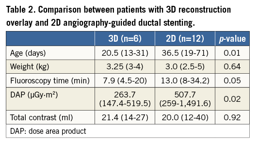
During the analysed period, 12 patients underwent ductal stenting with traditional 2D angiographic guidance (Online Table 1). A single self-expanding stent was implanted in all patients, with five patients having balloon atrial septostomy during the same catheterisation. Table 2 presents a comparison between those with 3D reconstruction overlay and 2D angiography-guided ductal stenting. The 2D angiography patients were treated at an older age and received a higher radiation dose.
Discussion
Three-dimensional rotational angiography introduces modern, advanced imaging into the grey world of 2D angiography. It has been shown to improve diagnostic accuracy during catheterisation of various congenital and acquired heart defects7-10. Moreover, the ability to overlay the reconstructed image on live fluoroscopy has brought additional value in catheter-based interventions15,16.
The first reports on applications of 3DRA in cardiovascular lesions focused on the quality of images obtained from RA and added information gained from 3D reconstruction. Glatz et al described their initial experience with this modality in a heterogeneous group of 41 patients7. Diagnostic quality images were obtained in 71% of patients; however, 3D reconstruction was used to guide interventions in only two patients. Later, Berman et al reported a group of 32 patients with cavopulmonary connections, in whom 89% of 3DRAs were judged to be of adequate diagnostic value8. Most recently, Glöckler et al achieved high-quality images in 96.6% of 176 reported highly variable cases15. In the latter two groups, 3D reconstructed images were used as an overlay on the fluoroscopy screen to guide the majority of interventions. Finally, our report focuses on the exclusive use of deliberately manipulated 3D reconstruction to guide ductal stenting in initial palliation of HLHS. This reflects the transition of 3DRA from a diagnostic modality to a reliable interventional guiding tool.
Favourable haemodynamic and anatomic factors, including slow blood transit time and limited vessel pulsatility, favour its use in single ventricle physiology. Indeed, in our wider experience, approximately 75% of patients having 3DRA are on various stages of Fontan palliation. Ductal stenting, especially in duct-dependent systemic circulation, does not share the aforementioned favourable conditions. Angiography is performed in a high-flow area, where obtaining satisfactory images is usually more challenging. Manoeuvres, such as rapid pacing or adenosine administration, allow temporary reduction of cardiac output and limitation of contrast washout, but in this fragile group of patients such manoeuvres can lead to haemodynamic instability and may also hide the extent of vessel pulsatility during normal cardiac output7,8.
The size of the patients and of the target vessel adds to the challenges of performing 3DRA in this population. One of the first reports of 3DRA in congenital patients evaluated pulmonary veins in a 5 kg neonate, with structures similar in size to the arterial duct of a newborn7. However, slower pulmonary venous flow, especially in the setting of stenosis, allowed homogenous opacification of the target structures throughout the RA run. The use of 3DRA was also described in 4.3 kg and 4.8 kg patients after cavopulmonary connection, forgiving physiological contexts for RA8,15. In our previous experience with 3DRA, we were able to produce good-quality images of the right ventricle to pulmonary artery shunt and the pulmonary arteries in the early post-Norwood patients.
We can produce dynamic images in multiple projections of the anatomical features related to the structure placed in the isocentre obtained during the 4.1 second rotation. After creation of the static 3D reconstruction, volume-rendered structures can be viewed in any plane and can be rotated on any axis. We utilised both the dynamic RA images and static 3D reconstruction. We initially intended to compensate for not using rapid pacing by injecting full strength contrast, but with increasing experience we changed our practice to use 60-70% diluted contrast, without a negative impact on image quality. This reduced the contrast dose to 2.3 ml/kg/run, lower than in the patients with cavopulmonary connections described by Glöckler et al15. Although other groups reported lower contrast doses for a single RA run (1.4 ml/kg and 1.2 ml/kg), these were in larger patients, consistent with the observation that the dose of contrast per kilogram is inversely proportional to patient weight7,8.
In the studied population, contrast administered for RA constituted on average 83% of the total contrast load, higher than that reported by groups from Erlangen (35%) and Philadelphia (49%)7,15. Excluding the patient who received a hand contrast injection at the end of the procedure, the remaining patients required only small amounts of contrast to position the angiographic catheter. No further injections were made during stent introduction, positioning and deployment, confirming that, with experience, all of the required information can be obtained using RA.
Defining the ductal anatomy from the raw data set did not seem more challenging than for other lesions in our experience. Instead of merging the reconstructed duct as it was with live fluoroscopy, we intentionally modified the reconstruction to facilitate stent implantation. The ability to view the duct and the surrounding structures in unlimited planes enabled precise marking of landing points for the proximal and distal ends of the stent. Although the median time required for post-processing is reported as 9.5 min, this is probably significantly exaggerated due to the retrospective reporting of the timings. With growing experience, we were able to decrease the post-processing time to below 4-5 min.
Duration of the C-arm rotation, vessel pulsatility and breathing produce artefacts in 3D reconstruction7,10. Figure 1B represents typical “splitting” artefact of the proximal part of the angiographic catheter in the main pulmonary artery and the end of the venous central line placed in the right atrium. The greater the distance from the isocentre and the more mobile the structure, the more pronounced the splitting artefact observed. Therefore, we emphasise meticulous table set-up prior to the rotation to position the duct at the isocentre.
Despite these artefacts, we were able to obtain precise reconstruction of the duct in all attempted cases. Similarly, the overlay of the duct on the live fluoroscopy was accurately aligned in all patients. Because the reconstruction (created from images taken during breath-hold) does not follow breathing motion, we observed a minor degree of vertical shift in the sagittal plane of the stent during positioning and deployment. However, even with the added distortion of positioning a stiff wire and delivery system, we had no difficulty in positioning and deploying the stents.
Since the introduction of the 3DRA in invasive imaging of congenital heart disease, radiation dose has been hotly debated, and efforts have been made to limit patient and staff exposure19,20. More recently, modified RA acquisition programmes allow radiation exposure comparable to similar in length biplane angiography7. When difference in size of the patients is taken into account, our radiation dose both for single RA and complete study is similar to that reported by others6-8,15. It is also within the range of the total estimated exposure during a routine paediatric cardiac catheterisation21.
When compared to our historical group of patients treated using the same angiography system but with 2D guidance, the study group received lower radiation and similar contrast doses. The historical group was treated at an older age and more frequently underwent simultaneous balloon atrial septostomy, reflecting the evolution of our practice. This comparison of the same intervention performed by the same team but with 2D or 3D guidance provides a strong argument in favour of 3DRA as a modern guiding tool.
Limitations
The limitations of the study are consistent with its retrospective nature. The rating of image quality for RA and 3D reconstruction as well as accurateness of the overlay is subjective. The small numbers of patients and minor changes in imaging technique hinder strong statistical analysis. The 3D reconstruction, based on data obtained from RA, requires post-processing, which gives the opportunity to alter the reconstructed volume in such a way that particular structures are highlighted, but at the same time it creates the risk of over-manipulation or misinterpretation. Also, the accuracy of 3D reconstruction overlay has to be critically evaluated for each target structure, and appropriate corrections need to be made to accommodate the distortion produced by pulsatility and the presence of stiff equipment. Computerised modelling to determine and account for these distortions as well as tagging for respiratory motion and vessel pulsatility are being developed, and will hopefully contribute to improved accuracy.
Conclusions
Three-dimensional rotational angiography provides accurate visualisation of ductal morphology and relative anatomy, including the origin of the pulmonary arteries and the aortic arch. Three-dimensional reconstruction overlay with clear landing points enabled precise stent implantation with no additional contrast injections and lower radiation doses than conventional angiography in our patients.
| Impact on daily practice Until now, the main application of 3DRA in congenital cardiology has been in low-velocity flow areas mostly used for interventions, such as cavopulmonary connections, coarctation of the aorta, pulmonary arteries or right ventricle to pulmonary artery conduits. Our initial experience with 3D reconstruction overlay for ductal stenting suggests that this technology has significant advantages over traditional 2D angiography. Continuing experience with 3DRA has allowed radiation doses to decrease significantly over recent years. This should give more confidence for operators to explore the benefits of 3DRA in a much wider range of congenital and structural cardiac conditions. |
Conflict of interest statement
The authors have no conflicts of interest to declare.
Supplementary data
Moving image 1. Three-dimensional rotational angiography-assisted arterial duct stenting. During 4.1 seconds and 240 degrees of isocentric rotation (Allura; Philips Healthcare), 12 ml of undiluted contrast was automatically injected through an angiographic catheter placed in the arterial duct. The delay of C-arm movement was set at 1 second. Deployment of a self-expanding stent was entirely guided with live post-processed 3D reconstruction overlay. For further reduction of radiation dose, stent implantation was recorded with stored fluoroscopy, which resulted in a lower quality of fluoroscopy images. Final rotational angiography was performed with similar settings to the initial angiography, with delay of the C-arm rotation shortened to 0.5 second. This resulted in better contrast filling of the vessels in right anterior projections but loss of steep left lateral projections. No obvious influence on the quality of the 3D reconstruction could be seen. On the post-processed maximum intensity projection 3D reconstruction, the retrograde aortic arch with originating vessels was spared for optimal appreciation of the spatial relations.
Supplementary data
To read the full content of this article, please download the PDF.
Three-dimensional rotational angiographyassisted arterial duct stenting. During 4.1 seconds and 240 degrees of isocentric rotation (Allura; Philips Healthcare), 12 ml of undiluted contrast was automatically injected through an angiographic catheter placed in the arterial duct. The delay of C-arm movement was set at 1 second. Deployment of a self-expanding stent was entirely guided with live post-processed 3D reconstruction overlay. For further reduction of radiation dose, stent implantation was recorded with stored fluoroscopy, which resulted in a lower quality of fluoroscopy images. Final rotational angiography was performed with similar settings to the initial angiography, with delay of the C-arm rotation shortened to 0.5 second. This resulted in better contrast filling of the vessels in right anterior projections but loss of steep left lateral projections. No obvious influence on the quality of the 3D reconstruction could be seen.