- percutaneous coronary intervention
- quantitative coronary angiography
- three-dimensional reconstruction
Abstract
Aims: To propose and validate a novel approach to determine the optimal angiographic viewing angles for a selected coronary (target) segment from X-ray coronary angiography, without the need to reconstruct the entire coronary tree in three-dimensions (3D), such that subsequent interventions are carried out from the best view.
Methods and results: The approach starts with standard quantitative coronary angiography (QCA) of the target vessel in two angiographic views. Next, the target vessel is reconstructed in 3D, and in a very simple and intuitive manner, the possible overlap of the target vessel and other vessel segments can be assessed, resulting in the best view with minimum foreshortening and overlap. A retrospective study including 67patients was set up for the validation. The overlap prediction result was compared with the true overlap on the available angiographic views (TEST views). The foreshortening for the views proposed by the new approach software viewing angle (SVA) and the views used during the stent deployment software viewing angle (EVA) were compared. Two experienced interventional cardiologists visually evaluated the success of SVA with respect to EVA. The evaluation results were graded into five values ranging from –2 to 2. The overlap prediction algorithm successfully predicted the overlap condition for all 235 TEST views. EVA was associated with more foreshortening than SVA (8.9%±8.2% vs. 1.6%±1.5%, p<0.001). The average evaluated point for the success of SVA was 0.94±0.80 (p <0.001), indicating that the evaluators were in favor of the optimal views determined by the proposed approach versus the views used during the actual intervention.
Conclusions: The proposed approach is able to accurately and quickly determine the optimal viewing angles for the online support of coronary interventions.
Introduction
Coronary angioplasty is an interventional procedure directed at opening obstructed arteries under the guidance of X-ray angiography. Despite the tremendous success of the procedure in the instant treatment of coronary artery disease, the occurrence of stent under expansion or incomplete lesion coverage due to suboptimal stent selection and deployment techniques could significantly increase the risks of restenosis and thrombosis1-4, hampering the translation of the procedural success into long-term positive outcomes.
Choosing appropriate angiographic views during coronary interventions is one of the important steps in the stent deployment and positioning, especially for complex bifurcation stenting. Optimal viewing angles are characterised by having minimal foreshortening of the target segment, and having minimal overlap with other coronary segments. Currently, three-dimensional quantitative coronary angiography (3D QCA) has been regarded as an adjunct tool for the determination of optimal viewing angles5-9. However, to the best knowledge of the authors, all the existing approaches would require that the entire coronary tree be reconstructed in order to calculate both foreshortening and possible overlap of the target vessel with other coronary vessels, and that requires a significant effort and time which is not available during the actual interventional procedure. Contrary to the existing methods, we have been looking for an approach that is able to predict the possible overlap between the target vessel and other coronary vessel segments without the need to carry out a 3D reconstruction of the entire coronary tree.
In this study, we propose and validate such a new approach for the rapid assessment of the optimal viewing angles of a target vessel including the assessment of the possible overlap with other coronary segments, without the need to reconstruct the entire coronary tree in 3D. Given the efficiency of the procedure, we believe that it will be very suitable for online support in the catheterisation laboratory. The basic principles of the approach and the results of the validation will be described in the following paragraphs.
Materials and methods
At the Zhujiang Hospital affiliated to the Southern Medical University (where approximately 800 coronary interventions are performed annually) in Guangzhou, China, 68 patients who underwent both coronary angiography and interventional stenting between May and October, 2009 were selected for this retrospective study. Inclusion criteria were: 1) patients had no prior history of coronary artery bypass surgery; 2) interventions were performed by interventional cardiologists with at least 10 years of experience in interventional cardiology; 3) angiographic images were recorded by digital flat-panel X-ray angiograms.
The first stented vessel segment was chosen as the target vessel to be reconstructed and analysed. Among the selected patients, one patient was excluded from the study due to the lack of a second angiographic view for the 3D reconstruction. Therefore, in total we studied 67 target vessels (LAD n=32, LCX n=15, RCA n=20). Angiographic images were recorded at 25 frames/s by a monoplane digital X-ray system (AXIOM-Artis; Siemens, Germany). All parameters required for the 3D reconstruction were stored in DICOM files.
Three-dimensional angiographic reconstruction
From the routine coronary angiography acquisitions, two image sequences acquired at two arbitrary angiographic views with at least 25 degrees apart in viewing angles were selected for the reconstruction. The 3D angiographic reconstruction consists of four major steps: 1) select the end-diastolic image frames with the vessel lumen well filled with contrast from the two image sequences as projection views for the subsequent 3D reconstruction; 2) identify one to three reference points, e.g., markers on the catheter and side branches, on both projection views for automated correcting of system distortions introduced by the isocentre offset and the respiration-induced heart motion6,10; 3) manually define the vessel segment of interest and extract its lumen contours and derived centrelines using our extensively validated QCA algorithms11-13 in the two angiographic views; and 4) reconstruct the 3D centreline and cross-sections after refining the correspondence between the two extracted centerlines6. In case of poor angiographic image quality, image enhancement techniques14 could be used to increase the visibility of detailed image structures for the identification of reference points in step 2.
An example of system distortions in the image geometry for the 3D reconstruction is given in Figure 1. The catheter tip and the bifurcation in the left circumflex artery (LCX) were identified as reference points and their epipolar lines, each being the projection of the X-ray beam directed towards a particular point on one of the projection views onto the second projection view15, were presented in the two projection views (1 RAO, 34 caudal and 28 RAO, 26 caudal, respectively). Due to the system distortions, the epipolar lines did not go through their corresponding reference points. After having applied the automated correction for the system distortions, the epipolar lines went right through their corresponding reference points in both projection views (Figure 2), demonstrated the success and quality of this automated procedure.
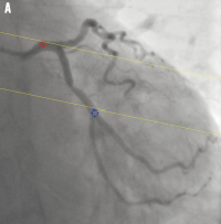
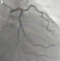
Figure 1. System distortion in the image geometry for the 3D reconstruction: A) is the first projection view (1 RAO, 34 caudal); B) is the second projection view (28 RAO, 26 caudal). The epipolar lines did not go through their corresponding reference point
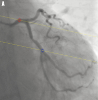
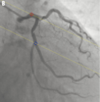
Figure 2. Automated correction of system distortion in the image geometry for the 3D reconstruction: A) is the first projection view (1 RAO, 34 caudal); B) is the second projection view (28 RAO, 26 caudal); the epipolar lines went right through their corresponding reference points in both projection views after the correction.
Figure 3a and b show the extracted 2D lumen contours and derived centrelines for the target vessel in the LCX, superimposed on the first and second projection views, respectively. Figure 3c shows the 3D reconstructed target vessel under 35 LAO, 37 caudal. The target vessel segment has a 3D length of 16.24 mm, a percent area obstruction of 59.4% and a derived percent diameter obstruction of 39.5%.
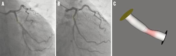
Figure 3. The extracted 2D contours and the 3D reconstructed target vessel: A) and B) are the two projection views with the superimposed 2D contours and centrelines; C) is the 3D reconstructed target vessel under 35 LAO, 37 caudal.
The determination of optimal viewing angles
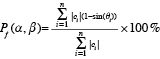
After the 3D reconstruction has been carried out, the amount of foreshortening of the target vessel for a selected view can easily be determined from the reconstructed centrelines. Given a viewing rotation angle α and angulation angle β, the percentage of foreshortening Pf for a set of centreline pieces C, being the lines connecting two consecutive centreline points, is calculated by the following formula:
 (1)
(1)
where ci is the tangent vector of the i-th centreline piece and θi is the angle between ci and the viewing vector associated with the viewing angle of α and β.
Those viewing angles characterised by minimal percentage of foreshortening of the diseased part (e.g., stented sub-segment) of the target vessel are selected as candidate viewing angles. In our implementation, the regression plane, that intersects the centre of the target vessel, is first calculated based on the condition that the sum of the distances from the plane to all the centreline points of the target vessel is maximised. Then, the five viewing angles on the regression plane with minimum foreshortening and at least 15degrees apart were automatically selected as the candidate viewing angles.
In the next step, we propose a novel algorithm to predict the overlap between the diseased part of the target vessel and other unreconstructed coronary segments under each of the selected candidate viewing angles. Based on such data one can exclude or better reject those viewing angles associated with significant overlap, i.e., overlap between the target vessel and major coronary arteries or their main branches, which could in practice significantly influence the visibility of the target vessel.
The principle of the overlap prediction algorithm can best be described and later illustrated by using the image geometry in the angiographic projection. Suppose that the target vessel overlaps with a vessel segment S under a particular viewing direction π. If the target vessel is virtually shifted in 3D along the viewing direction π, it will eventually intersect with segment S, and this can be checked by their projections from the two available angiographic views. On the contrary, if the two projections of the shifted target vessel in the two angiographic views never intersect with segmentS at the same time, while the target vessel is shifted virtually along the viewing direction π, there will be no overlap between the target vessel and segment S in the viewing direction π.
The aforementioned conceptualisation can best be illustrated by the example of Figure 4. The trajectory (the blue lines going though the centre of the target vessel) corresponding to the specified viewing angle is projected onto each of the two angiographic views that were used for the 3D reconstruction, e.g., Figures 4a and b. The target vessel (represented by means of its centreline in the two angiographic views) is shifted virtually along the trajectory and the possible overlap can be determined by the way the shifted target vessels intersect with the projections of other vessel segments in the two angiographic views. In this case, the algorithm predicted significant overlap of the target vessel with the mid left anterior descending (LAD) artery under the view of 29 LAO, 18 cranial, because the shifted target vessels, represented by the short curves coloured in red in Figure 4a and b, intersected with the mid LAD at the same time. Figure 4c shows the angiographic image acquired at that particular view of 29 LAO, 18 cranial, and this confirms that the proximal part of the target vessel overlaps with the mid LAD (indicated by the arrow). Figure 4d and e predicted that there was no overlap of the target vessel with other unreconstructed vessel segments under the view of 1 LAO, 34 caudal, because the shifted target vessels never intersected with the same vessel segment at the same time. Figure 4f shows the angiographic image acquired at 1 LAO, 34 caudal, and clearly, the target vessel does not have any overlap with other vessel segments.
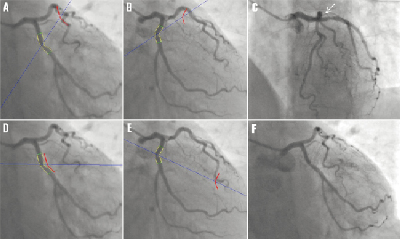
Figure 4. Comparisons of the predicted results from the overlap prediction algorithm with the actual angiographic projections: (A) and (B) predicted that the proximal part of the target vessel overlapped with the mid LAD under the viewing angle of 29 LAO, 18 cranial; (C) shows the actual image projection under 29 LAO, 18 cranial; (D) and (E) predicted that there was no overlap of the target vessel with the unreconstructed vessel segments under the viewing angle of 1 LAO, 34 caudal; (F) shows the actual image projection under 1 LAO, 34 caudal.
In vivo validation
Overlap prediction
For each patient studied, three to six angiographic projections (hereafter denoted as TEST views) were selected to validate the accuracy of the proposed overlap prediction algorithm; the number of TEST views were dependent on the total number of views recorded for a particular patient. The selection procedure was performed before the 3D angiographic reconstruction took place to guarantee that it was a blinded procedure. Next, the 3D target vessel was reconstructed and its overlap condition, i.e., whether the target vessel had any overlap with other vessel segments or not, under each of the TEST views was calculated by the prediction algorithm. The results were then compared with the true overlap condition in the available angiographic projections.
Optimal viewing angle
The difference in the optimal viewing angles determined by the proposed approach (hereafter denoted as software viewing angle, SVA) and the viewing angles used during the stent deployment in the actual intervention (hereafter denoted as expert viewing angle, EVA) was determined by calculating the angle between the viewing vectors associated with SVA and EVA, respectively. In addition, the percentages of foreshortening of the target vessel under the SVA and EVA were calculated and compared.
Two interventional cardiologists with 12 and eight years of experience in interventional cardiology independently evaluated the success of SVA, with respect to EVA. After carefully reviewing all the angiographic projections for each patient and the 3D reconstructed target vessel under the different viewing angles, the interventional cardiologists were requested to choose one of the following five candidate options:
A. SVA is significant worse than EVA;
B. SVA is slightly worse than EVA;
C. SVA is not much different from EVA;
D. SVA is slightly better than EVA;
E. SVA significant better than EVA.
These five candidate options were graded into five values ranging from –2 to 2 with a step of 1. The average graded value of the two interventional cardiologists was defined as the score point for the evaluated case. The sign of the score point indicates which viewing angle is better: positive for the viewing angle determined by the proposed approach and negative for the viewing angle used during the actual intervention.
Statistics
Quantitative data were presented as mean ± standard deviation, while the accuracy of the overlap prediction was presented as the percentage of successful predictions for all TEST views. The percentages of foreshortening of the target vessel under SVA and EVA were compared using the paired t-test. The sign of the score point for the evaluation of the success of SVA with respect to EVA was tested by using the Wilcoxon Signed Ranks test. A 2-sided p-value of <0.01 was considered to be significant. All statistical analyses were carried out by using a statistical software package (SPSS, version 16.0; SPSS Inc., Chicago, IL, USA).
Results
Overlap prediction
In total 235 TEST views from 67 patients were selected to validate the accuracy of the proposed overlap prediction algorithm. The algorithm successfully predicted the overlap condition for all the 235 TEST views. The accuracy of overlap prediction, therefore, was 100%.
Optimal viewing angle
In 16 (23.9%) of the cases both interventional cardiologists decided that SVA was significant better than EVA, while in none of the cases the interventional cardiologists found SVA worse than EVA. The frequencies of the graded evaluation results from the two interventional cardiologists are presented in Figure 5. Note also that the two interventional cardiologists scored very similarly. In addition, one can say that in about 60% of the cases they clearly favour the SVA approach. The average score point for the success of SVA with respect to EVA was 0.94±0.80. Statistical tests showed that the sign of the score point was positive (p <0.001), indicating that the interventional cardiologists were in favour of the viewing angles determined by the proposed approach as compared to the viewing angles used during the actual intervention.
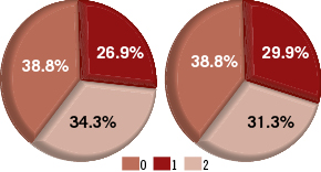
Figure 5. The proportions of the graded evaluation results from the two interventional cardiologists: Left is from the first cardiologist; Right is from the second cardiologist.
The difference in SVA and EVA ranged from 2.1º to 54.1º, with an average difference of 22.3º±12.3º. The percentage of foreshortening of the target vessels under SVA ranged from 0.2% to 7.4%, with an average value of 1.6%±1.5%, while the percentage of foreshortening of the same target vessels under EVA ranged from 0.4% to 40.1%, with an average value of 8.9%±8.2%. In other words, the viewing angles used during the actual intervention were associated with a much higher percentage of foreshortening than the optimal viewing angles determined by the proposed approach (difference: 7,2%±8.2%, p < 0.001). The average percentages of foreshortening under EVA in the LAD, LCA, and RCA were 7.5%±7.1%, 11.1%±7.6%, and 9.3%±10.2%, respectively. The frequencies of EVA associated with <10%, 10%-20%, and >20% foreshortening in different coronary segments are presented in Figure 6. In all, 7 (10.4%) target vessels had more than 20% foreshortening in the image projections during the actual intervention, while 19 (28.4%) target vessels had 10%-20% foreshortening and 41 (61.2%) target vessels had less than 10% foreshortening. On the contrary, 60 (89.6%) target vessels had less than 3% foreshortening under the viewing angles proposed by our approach.
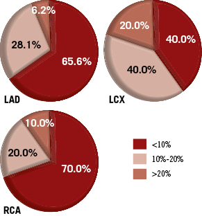
Figure 6. The proportions of EVA associated with different vessel foreshortening in the LAD, LCX, and RCA.
Scatter plots for the distributions of SVA and EVA in different coronary segments are presented in Figure 7. The data from Figure 7 suggest that the distribution of EVA is more concentrated than SVA, reflecting the fact that in general the interventionalists choose one of the more commonly used angiographic viewing angles16 and only slightly adjust it to use in the stent deployment. On the contrary, SVA distributes more evenly, indicating that there is significant variability in the optimal viewing angles based on the actual anatomy of the individual patient.
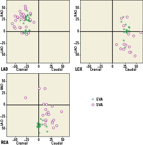
Figure 7. The distributions of SVA and EVA in the LAD, LCX, and RCA.
Discussion
Drug eluting stents (DES) have proven to be able to reduce the in-stent restenosis rate after the intervention17-19; however, the efficacy depends on complete lesion coverage, and therefore requires appropriate stent selection and deployment techniques1,20. The ad hoc solution of deploying additional stents when the first-select stent turns out to be of insufficient length or being deployed at suboptimal positions, could reduce the minimum stent area (MSA) and increase the dose of drug released in the overlapping area, which have been demonstrated to be associated with increased risks of restenosis and thrombosis21. In addition, the suboptimal stent deployment due to the unreliability in achieving the optimal viewing angle could result in undesirable results, e.g., stent protrusion into the main branch or incomplete lesion coverage at the ostium of the side branch might occur when stenting the obstructed segment at the ostium of a side branch2. In routine clinical practices, the optimal viewing angle is subjectively selected by adjusting the rotation angle (LAO/RAO) and angulation angle (cranial/caudal) of the X-ray gantry. This “trial-and-error” approach could significantly increase the amount of contrast medium administration and the radiation exposure to the patient and staff. Besides, due to the variable anatomy of the individual patient combined with the variable orientation of the heart in the thorax, there is no guarantee that the chosen angle will optimally visualise the target vessel during the stent positioning. In some cases, the identification of optimal viewing angles based on 2D angiographic projections is extremely challenging. Computer-aided stent selection and positioning are thus of great importance for the support of coronary interventions in catheterisation laboratories, especially with the increasing complexity of coronary interventions.
Three-dimensional quantitative coronary angiography based on routine angiographic projections has emerged as a new tool to increase the assessment capabilities for both diagnostic and interventional cardiology. It has been presented that by resolving a number of additional limitations of standard two-dimensional (2D) analysis11,22, such as elimination of foreshortening and out-of-plane magnification error23, 3D QCA could be used to accurately assess the length of vessel segment24-27 and change the decision making in stent selection24. In addition, the 3D angiographic reconstruction enables the subsequent automated determination of optimal viewing angles, which has been demonstrated to be associated with much less foreshortening of the vessel segments of interest as compared to the operator-selected views9 and hence, to enhance the capacities for the support of coronary interventions.
Despite that many advantages have been demonstrated by using 3D angiographic reconstruction to determine the optimal viewing angles6-9, the practical usage of such approach has been hampered by the fact that the calculation of optimal viewing angles with minimal foreshortening does not say anything about the possible overlap with other vessel segments, rendering such optimal views possibly useless. To actually calculate the possible overlap with other segments would require the reconstructing of the entire coronary tree. Since the reconstruction of the entire coronary tree from routine angiographic acquisitions not only requires a significant amount of time, but also imposes significant requirements on the angiographic image quality, e.g., without significant overlap between any of two visualised vessel segments, it is difficult to apply this approach in routine clinical practice.
To come up with an efficient and pragmatic solution, we have developed a new approach to determine the optimal viewing angles and minimise any possible overlap; in our approach we only need to reconstruct the target vessel. This new algorithm can easily predict the overlap conditions of the target vessel and other unreconstructed vessel segments, without the need to reconstruct the entire coronary tree. The execution time for the whole 3D reconstruction and overlap prediction is less than one minute on a standard PC. Although the calculation of optimal viewing angles could not reduce the need of multiple views to thoroughly study the lesion in pre-intervention, it provides the best view for the stent deployment and positioning during the intervention, which could be extremely difficult to realise based on the 2D X-ray angiography, especially with complex bifurcation stenting. An example case can be observed in stenting the ostium of the side branch28: an inappropriate view used in stent deployment might lead to stent protrusion into the main vessel branch or incomplete stent coverage at the ostium. Figure 8 shows the 3D reconstructed bifurcation under different viewing angles. Figure 8a and b show the angiographic view and the 3D reconstructed bifurcation under 31 RAO, 33 cranial, respectively. It is very clear from the 3D view that the visualisation of the ostium of the diagonal branch is not optimal. Positioning a stent at the ostium of the diagonal branch based on this viewing angle could easily result in undesirable results. Figure 8c shows the 3D bifurcation under the optimal viewing angle of 40 LAO, 56 cranial. The visualisation of the ostium of the diagonal branch has been greatly improved and optimised.
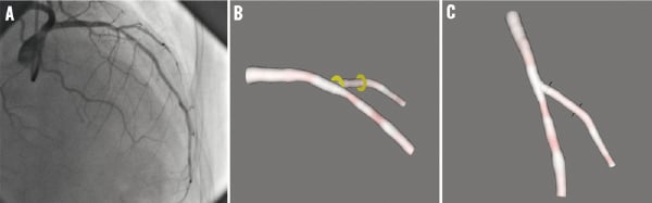
Figure 8. The visualisation of a bifurcation under different views: A) is the angiographic view under 31 RAO, 33 cranial; B) is the 3D reconstructed bifurcation under 31 RAO, 33 cranial; C) is the 3D reconstructed bifurcation under the optimal viewing angle of 40 LAO, 56 cranial.
In 60 (89.6%) of 67 target vessels in our study population, the proposed approach was able to determine the optimal viewing angles with less than 3% foreshortening and without overlap with major coronary branches which could influence the visibility of the target vessel, On the other hand, the experienced interventionalists were able to select a view with less than 3% foreshortening in only 19 (28.4%) target vessels and with more than 10% foreshortening in 26 (38.8%) target vessels. The optimal imaging of the LCX based on the experience of the interventionalists was the most challenging: 60% of the target vessels had more than 10% foreshortening under the viewing angles used during the actual intervention. These findings were similar to the results presented by Green9. The difference was that we found that the LAD, instead of the RCA, had the least foreshortening under the viewing angles used during the actual intervention. This difference could be partly explained by the facts that different data were used and different interventionalists were involved in these two studies. We would also like to point out that 19 angiograms were excluded from their study due to the technical insufficiency for the 3D reconstruction of the whole coronary tree, while only one angiogram of insufficient acquisitions for the 3D reconstruction of the target vessel needed to be excluded in our study.
One major limitation of this work is that it was a retrospective study and hence, the observers were not blinded to the approach when comparing the two different viewing angles. Therefore, prospective studies are still needed to fully validate the advantages of the proposed approach in stent deployment. However, the current results are very encouraging.
Conclusions
The proposed overlap prediction algorithm can accurately predict the overlap condition between the target vessel and the unreconstructed vessel segments. Our new approach is able to accurately and quickly determine the optimal viewing angles, which makes it suitable for the online support of coronary interventions.
Acknowledgements
The authors thank Jasper P. Janssen, MSc (LUMC), Andrei Rares, PhD (LUMC) and Joan C. Tuinenburg, MSc (LUMC & Medis) for their fruitful discussions on QCA.
Conflict of interest statement
Shengxian Tu and Gerhard Koning are employed by Medis Medical Imaging systems BV and have a research appointment at the Leiden University Medical Center. Johan H. C. Reiber is CEO for Medis Medical Imaging systems BV. The other authors have no conflicts of interest to declare.