CASE SUMMARY
BACKGROUND: An 89-year-old lady with severe aortic stenosis and NYHA Class III heart failure was referred for consideration of transcatheter aortic valve replacement.
INVESTIGATION: TTE, TOE, MDCT, left and right heart catheterisation, peripheral angiography, aortography.
DIAGNOSIS: Severe calcific aortic stenosis with 23 mm aortic annulus.
TREATMENT: Transcatheter aortic valve replacement using CoreValve device.
KEYWORDS: aortic stenosis, CoreValve prosthesis, transcatheter aortic valve replacement
PRESENTATION OF THE CASE
An 89-year-old lady with severe aortic stenosis and NYHA Class III heart failure who lives independently at home was referred for consideration of transcatheter aortic valve replacement (TAVR), using the CoreValve® prosthesis (Medtronic, Minneapolis, MN, USA). She had a background of hypertension, hypothyroidism and osteoarthritis. She weighed 67.5 kg and was 157 cm tall, with a BMI and BSA of 27.4 and 1.68 m2, respectively. Her logistic EuroSCORE and STS scores for risk of mortality were 13.6% and 5.4%, respectively.
She underwent multimodality imaging during the workup for TAVR. Transthoracic echocardiogram (TTE) demonstrated severely calcified and restricted aortic leaflets with a valve area of 0.7 cm2, mean gradient of 62 mmHg and dimensionless index of 0.22. She had normal left ventricular (LV) function and her aortic annulus measured 22.0 mm. Multi-detector CT (MDCT) using a 320 row-detector CT scanner demonstrated annulus dimensions of 22.7 mm and 22.9 mm as measured on the coronal and three-chamber reconstructions respectively (Figure 1A and Figure 1C). Using the double oblique transverse reconstructions, the maximum, minimal, average and cross-sectional area-derived annulus diameters were 27.3 mm, 21.2 mm, 24.3 mm and 23.7 mm, respectively (Figure 1B).
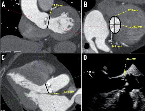
Figure 1. Annular assessment by MDCT and TEE. A) Coronal oblique reconstruction of the aortic root with an annulus diameter of 22.7 mm. B) Double oblique transverse images of the aortic root demonstrate an elliptoid shaped annulus with a maximum and minimal luminal diameter of 27.3 mm and 21.2 mm, respectively. The verage of the maximal and minimal diameter is 24.3 mm. The cross-sectional area is 445 mm2 and the derived diameter is 23.7 mm. C) Three-chamber reconstruction of the aortic root with an annulus diameter of 22.9 mm and (D) the corresponding mid-oesophageal long-axis echocardiography image, measuring 23.1 mm.
Left and right heart catheterisation was performed. She had mild pulmonary hypertension with a pulmonary artery pressure of 38 mmHg. On coronary angiography, apart from a 60% ostial stenosis in a moderate calibre first diagonal branch, there was otherwise mild non-occlusive disease in the major epicardial vessels. Aortography demonstrated significant aortic root angulation, characterised by the angle between the line of the plane of the annulus and the horizontal plane. This measured 60 degrees (Figure 2). Lastly, peripheral angiography was performed to assess her femoral access sites. The minimal diameters of bilateral femoral and iliac arteries all exceeded 6 mm. The left common iliac artery was tortuous, making the right side more appropriate for access.
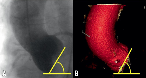
Figure 2. Aortic root angulation assessment by aortography and MDCT. A) Aortography acquired in the AP position and (B) MDCT volume rendered reconstruction demonstrates aortic root angulation of 60 degrees.
After discussion with the cardiothoracic surgeons, treatment with TAVR using the CoreValve® device was the preferred option over either open aortic valve replacement or conservative therapy. During the scheduled procedure, transoesophageal echocardiogram (TEE) was performed which demonstrated an annulus dimension of 23.1 mm (Figure 1D). Her aortic measurements are summarised in Table 1.
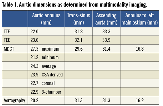
The annular dimension was 23 mm on both echocardiography and MDCT, although the mean of the maximal and minimal diameter on the transverse reconstruction was 24.3 mm. In the case of discrepant annular dimensions from different imaging modalities and views, the dimensions of which modality and view should be used ultimately to determine prosthesis size?
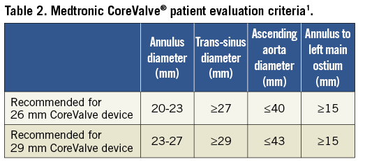
As the majority of the annular measurements were 23 mm, this diameter was chosen for prosthesis sizing. However, according to the Medtronic CoreValve® patient evaluation criteria1, it would be suitable to use either the 26 mm or the 29 mm device in a patient with a 23 mm diameter (Table 2). Which size should be chosen?
How would I treat?
THE INVITED EXPERT’S OPINION
This clinical case perfectly illustrates the dilemma we sometimes face when sizing the aortic annulus before TAVI and the discrepancies between echocardiography and MSCT1. To me, MSCT is the most appropriate technique to explore the dimensions of the aortic annulus and the features of the aortic root. This reproducible technique offers a three-dimensional view of the aortic annulus (virtual basal ring) with more precise evaluation of its shape and degree of calcification (load and distribution). MSCT studies demonstrated that the structure of the inflow portion of the Medtronic CoreValve® (MCV) conforms to the shape of the aortic annulus while the hoop strength in the mid-portion of the frame maintains circularity at the level of the supra-annular leaflets2. I would therefore rely on the cross-sectional area-derived diameter obtained by MSCT in double oblique transverse reconstructions: 23.7 mm, indicating a 29 mm device. One of the objectives is to achieve enough interference with the annulus to ensure a good sealing with no or minimal paravalvular leakage. Indeed, moderate regurgitation post TAVI is associated with an increased mortality3. In this case, if we consider that the mean diameter of the annulus is 23.7 mm, 26 mm and 29 mm MCV would respectively provide a maximal interference of 9.7% and 22.3%. Assuming that the optimal interference is around 15%, a 29 mm MCV is more appropriate to achieve that goal4. In the same way, if the area-derived diameter was 23 mm, I would still select a 29 mm device. The target depth of implantation should be 4 mm in order to locate the maximal diameter of the inflow portion at the level of the annulus. Apart from achieving an adequate interference with the aortic annulus, that implant depth could decrease the need for a subsequent pacemaker5.
In this case the verticality of the annulus is challenging and requires a good collaboration between operators. The first step will be to adjust the tension in the system, by gently pushing on the stiff wire and adjusting the position of the catheter, to keep the prosthesis perpendicular to the aortic annulus and coaxial to the aortic root. The role of the second operator will be of utmost importance, to adjust the tension on the wire regularly during the first third of deployment, in order to keep the position and the perpendicularity. I do not think there is a role for fast-pacing unless the operators face severe regurgitation post valvuloplasty with a back and forth movement of the prosthesis. Here a slow deployment should be fine.
So in summary, I would consider the cross-sectional area-derived diameter obtained by MSCT and treat this lady with a 29 mm MCV by the right transfemoral route, aiming high as regards the aortic annulus, with a very slow deployment and an active use of the guidewire to achieve a final implant depth of 4 mm.
Conflict of interest statement
D. Tchetche is proctor for Medtronic and Edwards.
How would I treat?
THE INVITED EXPERTS’ OPINION
Paravalvular leakage after transcatheter aortic valve implantation (TAVI) has been associated with adverse outcomes1,2. There are several aspects contributing to paravalvular leakage that have to be considered pre-interventionally: 1) Correct measurement of the aortic annular dimensions is the prerequisite for selecting the appropriate prosthesis and avoiding paravalvular leakage. Computed tomography (CT) has significant advantages over transoesophageal echocardiography (TOE) and is of particular importance in planning a TAVI procedure with the self-expanding Medtronic CoreValve® prosthesis3,4. Due to the oval shape of the annulus, cross-sectional area as well as perimeter measurements are used to derive a mean diameter of the aortic annulus, which in our experience is very reliable. However, correct measurement of the non-anatomical structure of the aortic annulus requires particular experience in multiplanar CT analysis. 2) The Medtronic CoreValve® prosthesis has peculiar design features that have to be considered in order to avoid paravalvular leakage. The nominal diameter of the prosthesis (in this case 26 or 29 mm) is maintained only over the first 4 mm of the inflow portion. Ideally, the prosthesis should thus be implanted 4-6 mm (high) into the left ventricular outflow tract (LVOT) to achieve an optimal seal. The waist (constrained part) of the prosthesis, however, has a diameter of only 22 mm for the 26 mm prosthesis and 24 mm for the 29 mm prosthesis. Too deep implantation of the prosthesis into the LVOT could therefore result in a mismatch between the prosthesis and annulus diameter. 3) Lastly, patient-related factors such as severe calcifications or very rigid leaflets can also result in paravalvular leakage but these factors cannot be influenced by the operator during the procedure.
In the present case, there is a borderline diameter of the aortic annulus which –according to the instructions for use– would be suitable for either the 26 mm or 29 mm Medtronic CoreValve prosthesis. We would select a 29 mm prosthesis for the following reasons: 1) TOE often underestimates the diameter of the aortic annulus when compared to CT4. In this patient, TOE already measured 23 mm for the annulus. Looking closely to the CT, the mean diameter derived from the cross-sectional area is almost 24 mm and the maximum diameter of the oval-shaped annulus by CT is 27.3 mm. 2) Figure 1A suggests a somewhat horizontal off-take of the aorta from the left ventricle. Implantation of the Medtronic CoreValve prosthesis exactly at the optimal height within the LVOT could thus be cumbersome. Selection of the larger 29 mm prosthesis therefore compensates for an anticipated position too low within the LVOT whilst still providing appropriate prosthesis diameter (at the waist) for sufficient seal. 3) What is the risk of selecting a 3 mm larger self-expandable TAVI prosthesis in this borderline case? We do not believe that there is an increased risk of annular rupture by potentially oversizing the self-expandable Medtronic CoreValve prosthesis. In contrast to balloon-expandable TAVI prostheses5, the risk of annular rupture with the Medtronic CoreValve prosthesis is very low. Current data suggest an association of new pacemaker implantation after TAVI with the implantation depth of the prosthesis6. Theoretically, increased radial forces to the LVOT due to oversizing of the prosthesis could increase the need for pacemaker implantation after TAVI. Data on valve size/aortic annulus ratio as a predictor of new pacemaker implantation after Medtronic CoreValve TAVI are, however, conflicting7,8. In this 89-year-old patient, we would be more concerned by significant paravalvular leakage than new pacemaker implantation which is also corroborated by recent data from the large-scale ADVANCE study showing no adverse outcome of patients requiring new pacemaker after TAVI compared to those without pacemaker. For selection of the prosthesis, the width of the aortic sinus should also be considered since too small a sinus diameter could result in coronary obstruction.
One could also suggest using intraprocedural balloon sizing for decision making. If simultaneous angiography during pre-TAVI valvuloplasty with a 23 mm balloon shows complete seal, one could decide to use the smaller 26 mm prosthesis. We believe that this is a very helpful strategy in borderline cases when using the balloon-expandable TAVI prosthesis, but we would not use this approach in the present patient. As stated above, for the Medtronic CoreValve prosthesis, implantation at a high (optimal) position within the LVOT is crucial for avoiding paravalvular leakage. However, even for very experienced operators, exact implantation of the device at the optimal height within the LVOT is often difficult, particularly in the present case due to the horizontal off-take of the aorta. In the worst case scenario of very deep implantation, the waist diameter of 22 mm will result in significant leakage. In patients for whom exact implantation at the optimal height is expected to be difficult, liberally oversizing the Medtronic CoreValve prosthesis to compensate for this has, in our experience, proved to be an effective strategy.
Conflict of interest statement
The authors have no conflicts of interest to declare.
How did I treat?
ACTUAL TREATMENT AND MANAGEMENT OF THE CASE
TAVR was performed under general anaesthesia as per our routine practice. This facilitates simultaneous TEE imaging which helps prosthesis sizing and provides real-time feedback of valve positioning and complications.
Bifemoral access was obtained. A 10 Fr Prostar® “pre-closure” device (Abbott Vascular, Redwood City, CA, USA) was inserted via a contrast-guided right femoral artery puncture. Once secured, an 18 Fr Cook sheath (Cook Medical, Bloomington, IN, USA) was inserted over an extra-stiff Amplatzer wire (Cook Medical) under fluoroscopic control. Valvuloplasty was successfully performed using a 12 Fr 4x20 NuCLEUS™ balloon (NuMED, Hopkinton, NY, USA) which resulted in mild to moderate aortic regurgitation (Moving image 1A and Moving image 1B).
Whilst guidelines recommended the suitability of either the 26 mm or 29 mm device1, the 29 mm device was chosen to minimise post-deployment paravalvular leak, valve migration and valve malapposition and to accommodate the angular eccentricity of the ellipsoid annulus best.
The device was initially difficult to position across the aortic valve secondary to unfavourable aortic root angulation and the suboptimal positioning of the extra-stiff Amplatzer wire in the LV, despite multiple attempts to position the wire more favourably. Nevertheless, upon successful valve crossing, the angle was optimised (Moving image 2A) and the ventricular end of the device was positioned 6-8 mm below the annulus (Moving image 2B).
Three challenges were subsequently encountered. The first occurred upon initial deployment when the device dived forward into the LV (Moving image 3A). As a result, the partially deployed device became deeply seated within the LV (Moving image 3B) such that the ventricular end almost extended towards the tip of the anterior mitral leaflet as demonstrated on TEE (Figure 3A and Figure 3B). The difficulty encountered when attempting to reposition the prosthesis superiorly was the second challenge and was well documented on TEE and fluoroscopy. Upon continuous traction, the force applied resulted in shortening the aortic arch thus tilting the prosthesis superiorly without successful “aortic” traction on the device (Figure 3C, Moving image 3C). TEE demonstrated the ventricular end had in fact moved beyond the anterior mitral leaflet tip (Figure 3D) after traction. With further force, the device was pulled back into the ascending aorta with the resultant need to retrieve the device. This was the third challenge as it involved dragging the partially deployed device from the ascending aorta and recapturing it back into the 18 Fr sheath in the descending aorta. Whilst its passage in the aorta had little resistance, the radial strength of the partially deployed nitinol valve made it difficult to resheath in the descending aorta (Moving image 4A), and easier to recapture in the right common iliac artery, using the latter for anchorage (Moving image 4B).
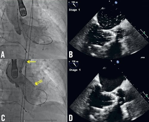
Figure 3. Attempt to reposition the 29 mm prosthesis. A) Aortography demonstrates the prosthesis is deeply seated within the LV; B) Corresponding TEE confirms that the ventricular end extends beyond the LVOT and meets the anterior mitral leaflet tip; C) Aortography, acquired after attempting to reposition the device superiorly, demonstrates the prosthesis remains in the same position. The force applied resulted in shortening the aortic arch (yellow arrow) and tilting the mitral valve (double yellow arrows) without effective superior repositioning; D) Corresponding TEE confirms that the ventricular end had in fact moved beyond the tip of the anterior mitral leaflet after continuous traction.
A second attempt at TAVR was performed using the 26 mm device. The ventricular end was positioned 6-8 mm below the annulus (Figure 4A and Figure 4B). During deployment and release, the prosthesis remained well seated in the LVOT without impinging the anterior mitral leaflet (Figure 4C and Figure 4D). TEE and aortography demonstrated adequate final positioning with minor periprosthetic leak (Figure 4E and Figure 4F).
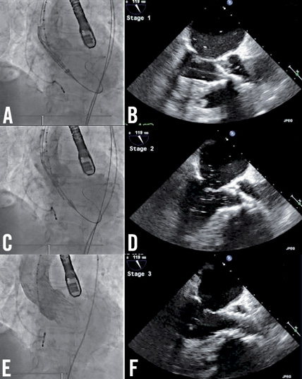
Figure 4. Positioning and deploying the 26 mm prosthesis. A) Aortography demonstrates adequate positioning of the ventricular end of the prosthesis which is confirmed on (B) the corresponding TEE. Adequate prosthesis positioning is demonstrated on aortography and corresponding TEE after partial deployment (C, D) and after device release (E, F).
The right femoral artery was successfully closed using the Prostar® device (Abbott Vascular) which was confirmed on angiography. The left femoral artery was closed using a Mynx® device (AccessClosure Inc., Mountain View, CA, USA). The patient was extubated successfully and transferred to the coronary care unit.
Upon arrival, she was found to have critical limb ischaemia in the left leg. As the differential diagnoses included access site occlusion and thromboembolism or dissection from the distal aorta, she underwent CT lower limb angiography before emergency vascular surgery.
CT demonstrated thrombotic occlusion of the left superficial (LSFA) and left profunda (LPFA) femoral arteries (Figure 5A, Moving image 5). The site of occlusion was 6 cm below the access site in the left common femoral artery (LCFA), which was patent, with no dissection, thrombus, or extrinsic compression. CT of the distal aorta demonstrated extensive infrarenal atherosclerotic plaque with features suggestive, yet not conclusive, of plaque disruption and thrombosis (Figure 5B).
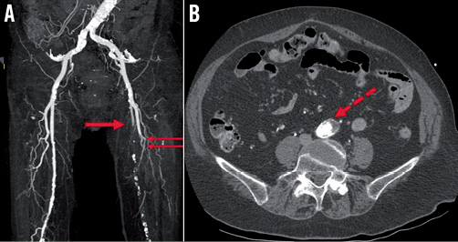
Figure 5. Lower limb computed tomography angiography. A) CT demonstrates thrombotic occlusion of the left superficial (red arrow) and left profunda (double red arrows) femoral arteries. B) Axial CT of the abdominal aorta demonstrates extensive infrarenal atherosclerotic plaque (dotted red arrow) with features suggestive of plaque disruption and thrombosis.
Emergency surgical embolectomy was performed using a LCFA cutdown approach. A large amount of thrombus was extracted from the LSFA and LPFA and flow was re-established.
Postoperatively, she experienced persistent profound hypotension and required inotropes for circulatory support. TTE excluded possible cardiac causes namely tamponade, paravalvular leak and aortic dissection, but demonstrated hyperdynamic LV function, with a well-seated prosthesis and a normal paravalvular gradient. She had no features of retroperitoneal haemorrhage on clinical examination and her haemoglobin remained stable. Abdominal CT was deferred due to concern regarding additional contrast administration. An abdominal ultrasound was performed instead which demonstrated no intra-abdominal collection, abdominal aortic dissection or perforation.
Over the ensuing 36 hours, she remained hypotensive despite adequate filling as per the recorded central venous pressure. Broad spectrum antibiotics were commenced to cover sepsis. Distal embolisation in other branches of the distal aorta was suspected including the mesenteric and renal circulation and accordingly the patient was anticoagulated. Despite this, the patient developed rhabdomyolysis and intractable renal failure characterised by severe and uncorrectable acidosis and hyperkalaemia, followed by multi-organ failure involving her liver and lungs. She died 60 hours after initial TAVR. The family declined a post-mortem examination.
Discussion and conclusion
TAVR is an established alternative treatment for patients with severe symptomatic aortic stenosis who are at too high a risk for conventional aortic valve replacement2,3 and is reported to have non-inferior outcomes when compared with surgery in high-risk surgical candidates4.
Several methods are recommended for prosthesis sizing using echocardiography5 and MDCT6,7. The latter may account better for the three-dimensional elliptical shape of the annulus6,7. Yet there is currently no universally accepted method and modality for annular assessment8. In the case of discrepant annular dimensions determined from different modalities and views, it is not known which should ultimately be used to determine prosthesis size and minimise risk of complications.
In patients with a 23 mm annulus diameter, the manufacturer’s criteria specify the use of either the 26 mm or the 29 mm CoreValve device1. In the present case, the trans-sinus and ascending aortic dimensions were also appropriate for either device. Our decision to choose the larger device was to prevent post-deployment paravalvular leak9, valve migration and valve malapposition10.
However, our choice proved to be inappropriate. We retrospectively reconsidered the LVOT dimensions and aortic root angulation in this 157 cm-tall lady. The “26 mm” or “29 mm” prosthesis refers to its ventricular inflow dimension, which is engineered to be positioned in the superior aspect of the LVOT. On MDCT, our patient’s maximal, minimal and average LVOT diameters were 26.4 mm, 18.6 mm, and 22.5 mm, respectively (Figure 6). Clearly, it would have been difficult for the chosen 29 mm prosthesis to be positioned in the LVOT. This may explain why the prosthesis dived deeply into the LV which has a larger diameter. Furthermore, on TEE her LVOT appeared crowded and short with a steep angle between the ascending aorta and LV (Moving image 6). This increased the difficulty in positioning the ventricular end of any prosthesis entirely within the superior aspect of the LVOT and not beyond. Lastly, the steep aortic root angulation acted against any force applied to reposition the device from the LV to a superior position. In our patient the applied force only succeeded in shortening the aortic arch and tilting the device (Figure 3).
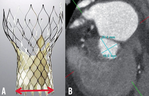
Figure 6. Consideration of LVOT anatomy. A) CoreValve device: the ventricular end of the device is designed to fit in the LVOT and (red line) measures 26 mm and 29 mm in the small and large prostheses. B) MDCT: double oblique transverse reconstruction of the LVOT demonstrates a maximal and minimal diameter of 26.4 mm and 18.6 mm, respectively.
The incidence of vascular complications using the 18 Fr Medtronic CoreValve system is 4-13%11. The development of critical limb ischaemia is uncommon and usually involves the limb used for CoreValve deployment secondary to sheath and closure device-related complications. In this case, the ischaemic limb was on the contralateral side and occurred as a consequence of thromboembolism in the LSFA and LPFA. Whilst thromboembolism may have originated from the LCFA access site, CT findings were not suggestive of this. The source was probably the abdominal aorta in which the device was dragged and retrieved. The 18 Fr sheath on the right side during this process probably protected the right leg from thromboembolism.
In conclusion this case highlights five important points:
1) In the absence of a gold standard method of assessment for prosthesis sizing, multimodality imaging of the aortic annulus is vital.
2) In patients “on the cusp of one or other valve size” factors other than measurements of the annulus should be considered, including aortic root angle, LVOT dimensions and, importantly, the size of the patient.
3) Intraoperative TOE may be useful in guiding real-time device positioning.
4) Whilst it may be reassuring that the CoreValve® device provides the interventionalist with the unique ability to reposition and retrieve a partially deployed device, repositioning is not the same as good primary positioning of the correct valve.
5) Lastly, to our knowledge, this is the first report of critical limb ischaemia as a result of thromboembolism occurring immediately after dragging and recapturing a partially deployed prosthesis. This case therefore illustrates the potential consequences in patients with aorto-iliac atherosclerotic disease.
Conflict of interest statement
I.T. Meredith serves on the scientific advisory board for the structural heart programme in Medtronic. The other authors have no conflicts of interest to declare.
Online data supplement
Moving image 1A. Balloon aortic valvuloplasty.
Moving image 1B. Post valvuloplasty.
Moving image 2A. Initial positioning of the 29 mm prosthesis across the aortic valve.
Moving image 2B. Aortography to position the 29 mm prosthesis.
Moving image 3A. Partial prosthesis deployment resulting in the 29 mm prosthesis diving into the LV.
Moving image 3B. Aortography demonstrating the 29 mm prosthesis in the LV.
Moving image 3C. Aortography demonstrating no shift in the 29 mm prosthesis upon continuous traction.
Moving image 4A. Attempts at retrieving the 29 mm prosthesis into the sheath in the abdominal aorta.
Moving image 4B. Final retrieval of the 29 mm prosthesis using the right common iliac artery for anchorage.
Moving image 5. CT lower limb angiography.
Moving image 6. Transoesophageal echocardiography of LVOT.
