CASE SUMMARY
BACKGROUND: An 81-year-old male with symptoms of angina and dyspnoea (NYHA 3), a history of coronary bypass surgery, a transaortic peak gradient of 109mmHg on transthoracic echocardiography and a logistic EuroSCORE of 21.6 was deemed suboptimal for surgery by a multidisciplinary team and was accepted for TAVI.
INVESTIGATION: Preprocedural diameter of the native aortic root was 24.4 mm on transthoracic echocardiography (TTE), 26.9 mm on contrast angiography and 26.8mm by 30.2 mm on multislice computed tomography (MSCT).
DIAGNOSIS: Heavy calcification of the aortic root and coronary arteries by MSCT.
TREATMENT: Transcatheter aortic valve replacement with an 29 mm CoreValve prosthesis.
KEYWORDS: aortic valve stenosis, TAVI
PRESENTATION OF THE CASE
The valve implant procedure has been described in detail elsewhere, but was performed without circulatory support. Aortic valvuloplasty was performed with a 22 mm diameter balloon before implantation of the CRS (CoreValve Revalving System; Medtronic, Minneapolis, MN, USA). The balloon appeared well expanded in the biplane images. A 29 mm inflow CRS was deployed in an optimal position with the ventricular end 6 mm below the base of the native leaflets (annulus) (Figure 1). Because asymmetric expansion of the frame was seen on fluoroscopy at the level of the heavily calcified native leaflets, post-dilatation was performed with a 25 mm balloon during rapid ventricular pacing. Unfortunately, the prosthesis displaced cranially due to premature discontinuation of the pacing, before the balloon was fully deflated, so that the ventricular end was at the level of the sinotubular junction. Severe paravalvular aortic regurgitation (grade 4) was immediately evident on invasive blood pressure monitoring and contrast angiography. A second 29 mm inflow CRS was implanted with the base of the skirt 11 mm below the base of the native leaflets, thereby compressing the leaflets of the first CRS (Figure 2). This improved the aortic regurgitation to grade 1 (Figure 2). No gradient was evident across the prostheses immediately following the procedure, although the patient was anaesthetised. The patient was treated in a high care unit with intravenous diuretics for mild fluid overload overnight and improved sufficiently to move to the medium care unit the following day. He was discharged five days later. Pre-discharge echocardiography demonstrated a transaortic gradient of 10mmHg.
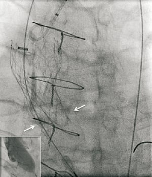
Figure 1. Balloon expansion during valvuloplasty (inset) and position of the first CRS after deployment relative to the native annulus (white arrows).
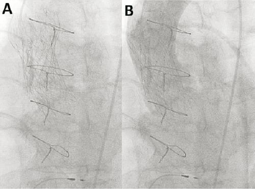
Figure 2. Appearance of valve in valve CRS™ (Panel A). Mild (grade 1) aortic regurgitation on contrast aortography (Panel B)
On routine review seven weeks later the patient was no better than before TAVI and complained of exertional dyspnoea (NYHA 3). A dual source MSCT was requested to better understand the morphology of the prostheses. The method has been described before1. The geometry of the CRS implanted second (second CRS) is reported because this is the valve from which the patient benefits. Under expansion of the frame of the second CRS at various levels of interest was quantified as the ratio of the measured cross-sectional surface area (CSA) divided by the nominal CSA. Deformation of the frame of the CRS was quantified by the ratio of the largest diameter (D2) divided by the smallest (D1) at each level of interest.
MSCT demonstrated that all three segments of the second CRS i.e., the inflow containing the skirt, the functionally important and constrained mid segment where the leaflet coapt, and the outflow section were severely under expanded and distorted (Figure 3). The cross-sectional surface area (CSA) of the mid-segment, where the leaflets coapt, was expanded to only 58% of the intended nominal value. The under expansion was maximal at the level of the outflow segment of the second CRS (normally the widest section which has no valve function, but normally serves to orient the device to blood flow), because it was positioned inside the narrowest (and highest hoop strength) section of the first CRS which prevented further expansion. In addition to underexpansion there was asymmetrical deformation of the inflow of the second CRS. This was caused by the calcified native leaflets (Figure 3). This asymmetrical deformation was also seen at the level where the leaflet coapt despite that the frame was circumferentially not apposed at this level, suggesting that the deformation of the inflow section of the CRS was propagated cranially due to stiffness of the frame (Figure 3). Severe deformation was seen at all levels, but was least at the ventricular end, and the apex of the outflow despite the severe under-expansion at the latter end (Figure 3).
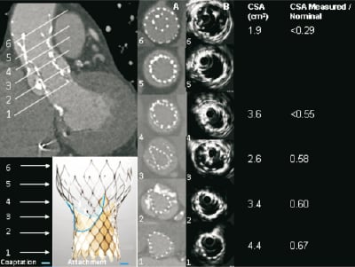
Figure 3. MSCT appearance of the CRS implanted first that embolised (higher and outside) and the second CRS (lower and inside the first). Axial images are shown at levels of interest (1-6) of the functionally important second CRS with corresponding measurements of cross-sectional surface area (CSA). Levels of the second CRS are: 1. ventricular end; 2. nadir of CRS leaflets; 3.central coaptation of CRS leaflets; 4. commissures; 5. nominally the widest point of 2nd CRS (central coaptation of 1st CRS); 6. apex of outflow. The frame of the device implanted first (higher) can be seen surrounding the frame of the second device from level 3 to 6.
Conflict of interest statement
The authors have no conflict of interest to declare.
Reference
How would I treat?
The Invited Experts’ opinion
Despite improvements in prosthesis design, significant aortic regurgitation (AR) is still not uncommon with both the Edwards SAPIEN and Core Valve Revalving System (CRS) prostheses1.
In cases of clinically significant para-prosthesis regurgitation after implantation, a careful evaluation of its mechanism must be carried out. It may be due to an undersized prosthesis or malpositioning of the device and necessitates specific treatment. In the absence of the above mechanisms, AR might be due to prosthesis under-deployment that can be treated by balloon post dilatation. This must be done under careful ventricular pacing to avoid leaflet damage or valve migration, which happened in the present case.
In cases of valve migration, a valve in valve implantation can be considered. A small series using the CRS has already been described2. In cases where the first prosthesis has been implanted too low, this strategy seems valuable, given the shape of the CRS. However, if the first prosthesis has been implanted too high, the “waist” of the first prosthesis, where the radial force is maximal, might cause under-deployment of the larger part of the 2nd prosthesis2. In this case, an Edwards prosthesis could be considered for the second valve due to its reduced height.
In the present case, a second CRS prosthesis was implanted inside the first prosthesis which had been implanted too high. This lead to under-deployment of the 2nd prosthesis due to: 1. the mechanism described above and 2. deformation of the inflow due to the calcified native leaflets.
Before considering an invasive strategy, the link between the symptoms and prosthesis under-deployment has to be firmly attested. A careful TEE evaluation should therefore be performed to confirm an elevated LV / Ao gradient. If confirmed, balloon post dilatation might help because of the asymmetrical deformation of the inflow due to the calcified native leaflets. However, even if successful, this manoeuvre will not expand the outflow tract since it is positioned inside the narrowest section of the first CRS.
Another possibility is to snare the first prosthesis leading to a sequential valve position. Ideally, this manoeuvre should be performed before implantation of the second prosthesis. After implantation of the second prosthesis, one could expect it to expand after snaring the first one. However, the success and safety of this technique is uncertain since traction on the first valve might pull the second valve at the same time.
Overall, even if at high risk for surgery, the patient has no formal operative contra-indications and surgery seems to be a reasonable option in the present case.
Conflict of interest statement
G. Ducrocq has no conflict to disclose. Dominique Himbert is a proctor for Edwards Lifesciences and Medtronic CoreValve, Alec Vahanian received speakers fees from Edwards Lifesciences and Medtronic CoreValve.
How would I treat?
The Invited Experts’ opinion
Emergent valve-in-valve procedure due to malposition or significant aortic regurgitation after implantation of a first transcatheter aortic valve is not uncommon. Among 514 consecutive patients treated with the CoreValve Revalving™ system (CRS) (Medtronic, Minneapolis, MN, USA), 4.3% of patients required a second valve within the first CRS device due to severe paravalvular leakage.1 The haemodynamic long-term consequences of this procedure remain unknown.
In the present case report, despite immediate success of an emergent valve-in-valve procedure, the patient did not show any clinical improvement after seven weeks of follow-up. Multidetector row computed tomography (MDCT) and intravascular ultrasound (IVUS) showed incomplete asymmetric expansion of the second device with significant constraint at the leaflet coaptation level.
The distorted and constrained deployment of the second CRS device inside the first prosthesis may affect the haemodynamic performance of the prosthesis and cause patient-prosthesis mismatch.2,3 The prevalence of severe prosthesis-patient mismatch after single CRS device implantation is 2-16% and the clinical consequences may include reduced functional improvement and increased long-term morbidity and mortality rates.2,3 However, the occurrence of prosthesis-patient mismatch after valve-in-valve procedures is unknown.
Positioning of the CRS prosthesis is one of the determinants of prosthesis-patient mismatch occurrence.2 The optimal positioning of this device is defined by a supra-annular placement of the valvular level and it is commonly achieved when the left ventricular edge of the frame is placed 5-10mm below the native non-coronary cusp as measured on fluoroscopy. “Shallow” (0-5 mm) or “deep” (10-15 mm) implants may result in significant aortic regurgitation or misdeployment of the device and are considered suboptimal positions.
Several “bail out” manoeuvres have been described to resolve a misplacement of the CRS device.4 The removing and reinserting technique can be employed when the prosthesis is deployed above the aortic valve annulus (“shallow” position). In this situation, the prosthesis is usually partially deployed and withdrawal and reinsertion into the 18Fr delivery system is possible during continuous flushing with cold saline (4º). When the prosthesis is positioned too deep, the snare technique can be applied. With an Amplatz GooseNeck™ Microsnare (EV3, Plymouth, MN, USA), one of the distal anchors of the prosthesis is snared and, by applying constant withdrawal force during 15-20 minutes, the prosthesis can be placed at a higher level. However, these interventions are associated with ahigh risk of complications (i.e., aortic dissection).
After valve-in-valve procedures, these interventions may be more challenging and the risk of complications may be higher. In addition, in this particular case, these manoeuvres may not be feasible after seven weeks of follow-up. MDCT and IVUS imaging data showed optimal position but significant under deployment of the second device with suboptimal apposition between the first and the second device at the leaflet coaptation level. Re-dilatation of the second device may be a feasible and safe alternative without risk for structural device damage. This manoeuvre may lead to a better deployment of the prosthesis and increased cross sectional area, resulting in improved haemodynamic performance of the prosthesis and symptoms relief. In addition, three-dimensional transesophageal echocardiography may be a valuable complementary tool to fluoroscopy for accurate procedural guidance and optimization of the results.
Conflict of interest statement
J. J. Bax receives grants from Biotronik, Medtronic, Boston Scientific, Lantheus medical imaging, St. Jude Medical, Edwards Lifesicences, and GE Healthcare. M. J. Schalij receives grants from Biotronik, Medtronic & Boston Scientific. The remaining authors have no conflicts of interest to disclose.
How did I treat?
Actual treatment and management of the case
For the 30 to 60% of patients with severe aortic stenosis who are at prohibitive surgical risk transcutaneous aortic valve implantation (TAVI,) is a rapidly emerging as a viable alternative treatment1-6. Early studies have been encouraging, but complication rates reflected the adverse risk profile of the patients and the learning curve of a novel procedure7-9.
One of the problems encountered during TAVI is severe regurgitation acutely following prosthesis implantation. This may occur after the implantation of either one of the two CE marked prostheses currently available in Europe10,11. Aortic regurgitation may occur because of prosthesis-host mismatch, under expansion due to the presence of bulky calcified native leaflets, recoil of the frame particularly when the leaflets are positioned at the level of the calcified native leaflets (balloon-expandable Edwards SAPIEN valve), or a final position that is either too high or too low relative to the native aortic annulus. The importance of the prosthesis position is explained by the fact that both valve technologies feature differing sealing mechanisms (segments of frame that are covered with pericardial material) to mitigate paravalvular aortic regurgitation after deployment. In the case of the CoreValve ReValving® system (CRS), the pericardial skirt covers the inflow section of the frame that is located below the leaflets and must be optimally positioned (with the ventricular end maximum 6 mm below the native annulus) to create a new seal in the left ventricular outflow tract (LVOT)8,11.
While CRS position can be adjusted during the stepwise delivery process, it cannot be repositioned once fully deployed. In the case of an incorrect CRS position complicated by haemodynamically significant aortic regurgitation (grade 3-4), the deployment of a second CRS in the correct position (valve-in-valve) has been proposed12. This approach can effectively deal with the problem of aortic regurgitation. Yet, there are very few reports assessing the final morphology of the implanted valves and it is conceivable that while the regurgitation has been resolved, residual stenosis may still be present. We report a patient where deployment of the second valve reduced aortic regurgitation without alleviating symptomatic valvular obstruction and evaluate with multislice computer tomography (MSCT) the effects of the frame of the first CRS on the deployment of the second.
In view of the incapacitating symptoms of the patient, the functional gradient on TTE and the anatomic information obtained from MSCT showing the severity of deformation of the CRS frame, in particular over the section where the leaflets coapt, the patient was re-admitted for a percutaneous dilatation of the frame.
Both of the implanted CRS prostheses were crossed using a 4Fr pigtail catheter without a Terumo guidewire to reduce the risk of crossing behind struts and to reduce risk of damage to the valve leaflets of the bioprosthesis. An invasive pressure gradient of 25mmHg was measured across the second CRS. Intravascular ultrasound was performed with a mechanised pullback at 0.5 mm per second across the CRS using an 8.3 MHz catheter (Volcano, Rancho Cordova, CA, USA). The dynamic IVUS images demonstrated severe compression of the valve leaflets, Figure 4. Post-dilatation was performed with a 23mm diameter balloon, but this did not much improve the asymmetrical deformation of the frame of the CRS at the level of the calcified native leaflets. A second post-dilation was performed with a 25 mm diameter balloon. This reduced the transvalvular gradient from 25 to 8 mmHg. Repeat IVUS indicated an improvement in the degree of deformation and the CSA at the level of leaflet coaptation, Figure 5. Aortic regurgitation (grade 2) was evident at the end of the procedure. The patient felt better immediately on rousing after the procedure and was transferred from high care to the medium care ward the following day. Repeat MSCT demonstrated an improvement in the CSA at the level of leaflet coaptation to 70% of the nominal value, Table 1 and Table 2, Figure 5 and Figure 6. Pre-discharge transthoracic echocardiography demonstrated a peak transvalvular gradient of 2mmHg without any aortic regurgitation. Figure 6 shows three-dimensional images of the valve in valve CRS’s before and after the final valvuloplasty.
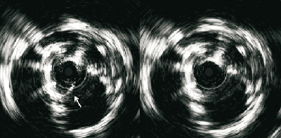
Figure 4. Intravascular ultrasound at the level of leaflet coaptation of the CRS implanted second demonstrated one leaflet closing (arrow) and opening freely with severe compression of the other two leaflets. The movement of the leaflets could be well appreciated from dynamic images.
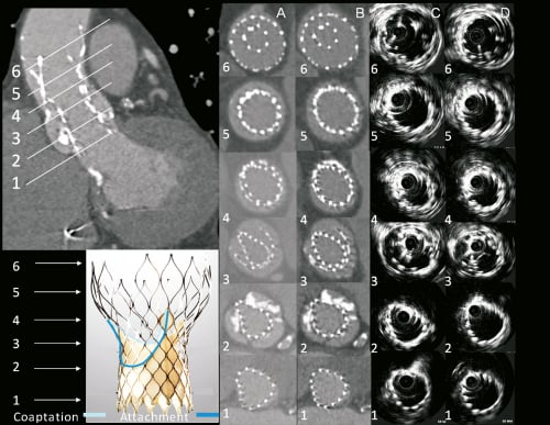
Figure 5. MSCT and intravascular ultrasound appearance of the CRS implanted first that embolised (higher and outside) and the second CRS (lower and inside the first). Axial images are shown at levels of interest (1-6) of the functionally important second CRS both before (columns A and C) and after (columns B and D) balloon valvuloplasty. Levels of the second CRS are: 1=Ventricular end, 2=nadir of CRS leaflets, 3=central coaptation of CRS leaflets, 4=commissures, 5=nominally the widest point of 2nd CRS (central coaptation of 1st CRS), 6=apex of outflow. The frame of the device implanted first (higher) can be seen surrounding the frame of the second device from level 3 to 6.
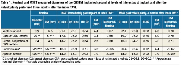
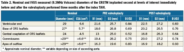
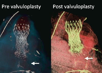
Figure 6. MSCT volume rendered images showing the frames of valve in valve CRS™’s before and after the valvuloplasty done threemonths after the index procedure. Arrows indicate calcified native leaflets at the base of the CRS™ implanted second.
Discussion
One of the striking observations of this case is the severe asymmetrical under-expansion of the CRS implanted first indicating that the initial balloon valvuloplasty did not overcome the calcified restriction of the native left and right aortic leaflets. A post hoc review of images of the aortic root pre-AVR showed that the movement of the left and right aortic leaflets during the cardiac cycle was minimal but that the leaflets were not fused and the levels of calcification, although dense, were similar to that seen in other patients treated successfully with TAVI. The native valve was also not bicuspid13. Although there was a discrepancy between the MSCT and TTE measurements of the native aortic annulus the recommended selection criteria for CRS implantation were based on TTE and not MSCT at the time of the index procedure. There is currently no consensus about what to do when such a discrepancy is encountered. We therefore proceeded on the basis of the TTE measurement, which was also compatible with the measurement on cine-angiography. We were not able to identify any other patient factors that could have predicted failure to expand the native leaflets.
The balloon diameter (22mm) was small relative to the diameter of the aortic annulus and may not have been sufficient to stretch open the native leaflets. However, the use of a larger size balloon could have increased the risk of aortic root complications including dissection, aortic rupture and stroke. During initial valvuloplasty the balloon expansion appeared adequate in the working angiographic view. It is possible, as discussed above, that the balloon was well expanded but was too small. However, the subsequent underexpansion of the CRS deployed first could only be detected in a view almost orthogonal to the working view. Although bi-plane imaging was used during the initial predilatation, the second C-arm was not in the plane of the valve so that balloon under expansions may have been more difficult to appreciate. The use of two C-arm positions (biplane) both in plane with the native valve may have allowed better detection of balloon underexpansion and post-dilation with a larger balloon before CRS implantation. Preprocedural MSCT is possibly the best tool for determining the optimal angulations for more than one C-arm14.
This case illustrates the potential complexity in dealing with significant aortic regurgitation due to an incorrect final position of the fully deployed CRS. Successful valve-in-valve deployment with good medium term outcome has been reported when the first valve was positioned too low in the LVOT15. Functionally this good outcome is possible when the first valve is implanted too deep so that the wider outflow portion of the second CRS is positioned cranial to the one deployed first thereby maintaining ample space to expand. However, if the first CRS is positioned too high and with the ventricular end less than 40 to 50mm above from the native annulus then optimal deployment of a second CRS may be compromised by under expansion similar to the present case. By design the middle segment of the CRS where the leaflets coapt is constrained, to preserve optimal leaflet coaptation, but also has high hoop strength to resist external compression. Therefore the CRS frame has the potential to overcome severe restriction of the native leaflets even if predilatation were to be inadequate. It is likely in the present case that the extreme under expansion of the outflow segment of the second CRS reduced the hoop strength of the constrained segment by mechanical transmission of the compressive force along the frame, leaving it vulnerable also to the effects of external compression by the calcified and constrained native leaflets. This may explain the asymmetrical deformation of the mid segment of the second CRS by the calcified native leaflets despite predilatation being performed twice. To avoid the scenario described here in cases where the position of a deployed CRS is too high, but not high enough to avoid interfering with optimal expansion should a second CRS be deployed in the optimal position, presents a challenge. Options that may be considered include: 1) snaring and displacing the first CRS cranially at least 44 mm above the base of the native leaflets before deploying the second (intuitively this approach may increase the risk of stroke), 2) dilating the basal and or mid segments of the CRS to allow sufficient space for deployment of the second (this approach may damage the CRS leaflets and might not work in the constrained segment due to high hoop strength), 3) the use of a different type of prosthesis could be considered. Finally, it is important to very carefully consider all the aortic root diameters particularly on MSCT when accepting a patient for TAVI. MSCT is intuitively the preferred method to define the base of the aortic root. The question is how to translate the MSCT measurements of the non-circular annulus into the decision of valve sizing and this must ultimately be accomplished by a comparative review of the results of multiple diagnostic vehicles. Until a wider size range of devices is available it will be unfortunate, but unavoidable that some patients cannot be treated.
Dual source MSCT provided a 3D dataset that allows accurate coaxial measurements of the complex anatomy of the aortic root and double CRS geometry, without significant signal loss due to calcification and layers of metal struts. These are advantages over 2D modalities such as extra-vascular echocardiography and contrast aortography. The Doppler derived peak gradient in combination with the detailed morphologic information derived from MSCT was essential in further patient management. However, a major drawback of MSCT is that it cannot provide information to the interventionist during a procedure. This underscores the role of transesophageal echocardiography (TEE) during TAVI. If TEE had been used during the index procedure the incomplete expansion of the second CRS would most likely have been recognised and corrected, thereby avoiding the need of the second intervention at three months. In our practice, we do not routinely use TEE. An alternative approach may be to use a mechanised pullback of a 8.3 MHz IVUS catheter, as was done during the second intervention. Given the potential risk of damaging the CRS leaflets we used IVUS only given the exceptional characteristics and complexity of this case. It has to be acknowledged that the IVUS pullback through the length of the CRS provided images that were affected by significant signal loss and side-lobe artefact, but the shape of the CRS frame and even the movement of the CRS leaflets could be appreciated. Importantly the diameter measurements of the CRS frame were similar to those obtained from MSCT. The IVUS measurements appeared slightly but consistently larger than those obtained from MSCT (Table 1 and Table 2). This is likely due to the fact that perfectly axial measurements cannot be ensured with the IVUS pullback. However, it is evident that in the present case the IVUS catheter was always located to one side of the CRS frame (Figure 4) indicating that the imaging plane was not far from being axial. In the present case the initial unforeseen problem (asymmetrical deformation of the CRS despite preceding balloon valvotomy) might have been caused by the fact that the predilatation balloon (22 mm) was too small, given the diameter of the native annulus on MSCT (26,7×30.2 mm), to fully crack open the heavily calcified native aortic leaflets. To the problem of asymmetrical underexpansion was applied an apparently reasonable remedy but was followed by an unexpected complication (CRS embolisation due to premature termination of pacing during post-dilatation). The occurrence of unforeseen obstacles may not be unusual in the multiple comorbid patient population who currently receive TAVI. Despite the noisy images IVUS can be useful to facilitate decision making when dealing with complex problems in TAVI.
In summary, the experience in this patient underscores that TAVI is a complex procedure where still a lot needs to be elucidated, such as adequate patient selection (both from a clinical and an anatomical perspective), planning and guidance. It also highlights the importance of international cooperation and the sharing of experiences, especially of complicated cases. In addition, thoughtful and detailed follow-up is mandatory certainly in the presence of unexpected findings such as residual symptoms after an apparently successful index bailout procedure. Valve-in-valve procedures should be avoided by all means possible, not only because of risks inherent to a prolonged and complex procedure, the unforeseen consequences such as those we encountered here, and the potential increased risk of thrombogenicity due to the high metal load and overlap of non-apposing struts.