Virtual bench testing is an established method to gain valuable insights in percutaneous coronary intervention (PCI) of bifurcation lesions. A previous study described virtual bench testing of the first generation of the Tryton (Tryton Medical, Inc., Durham, NC, USA) dedicated bifurcation stent, mounted on a straight delivery balloon1. However, nowadays most Tryton stents are implanted on a stepped delivery balloon to adapt to the fractal geometry of bifurcation lesions2. Virtual stent deployment using a stepped delivery balloon is challenging and has not been reported before.
A free expansion simulation of the Tryton stent mounted on a stepped delivery balloon (Moving Image 1, Moving image 2) was performed at increasing balloon pressures up to 12 atm, which is the nominal pressure (Figure 1A-Figure 1F), and compared with the actual free expansion of the “real” stent (Figure 1A’-Figure 1F’). Figure 1G (distal part of balloon) and Figure 1H (proximal part of balloon), shows a good agreement in pressure-diameter curves between the simulation and the data as provided by the manufacturer. The maximum percentage difference in diameter is 1.5% and 2.1% at 12 atm for the distal and proximal parts, respectively. The simulation also captured the abrupt expansion of the proximal part followed by the distal one.
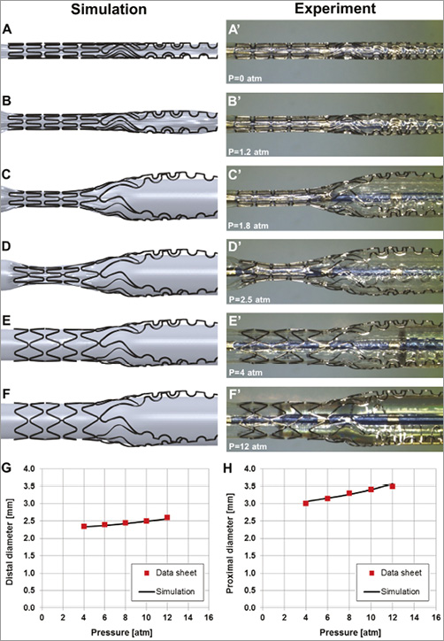
Figure 1. Free expansion simulations of the Tryton stent mounted on a stepped balloon and comparison with “real-time” experiments.
These findings demonstrate the feasibility of creating an accurate model of a dedicated bifurcation stent mounted on a stepped balloon. This model can be used for future virtual bench tests investigating Tryton stent behaviour in anatomical configurations with different angles, plaque morphology, and vessel diameters.
Guest Editor
This paper was Guest edited by Nicolas Foin, MSc, PhD; National Heart Centre Singapore, Singapore.
Conflict of interest statement
P. Serruys is chairman of the Tryton IDE trial. The other authors have no conflicts of interest to declare. The Guest Editor has no conflicts of interest to declare.
Online data supplement
Moving image 1. Simulation of the free Tryton stent expansion.
Moving image 2. Simulation of the free Tryton stent expansion, including pictures from the “real-life” experiments.
Methods
EXPERIMENT
In vitro free expansion of a Tryton stent (Tryton Medical Inc., Durham, NC, USA) with a length of 19 mm and a step delivery system of 2.5×3.5 mm was performed up to 12 atm. Images of the stent and the delivery system were acquired at increasing values of pressure using the Leica Wild M8 stereo microscope (Leica Microsystems, Wetzlar, Germany) with a Leica DFC290 digital camera.
SIMULATION OF STENT EXPANSION
The three-dimensional (3D) geometrical model of the Tryton stent was created in its crimped configuration from stereomicroscope images using the CAD software SolidWorks (Dassault Systèmes SolidWorks Corp., Waltham, MA, USA). The length, the internal diameter, and the strut thickness were 19 mm, 1.012 mm, and 0.084 mm, respectively. The stent is made of a cobalt-chromium alloy that was described by a von Mises-Hill plasticity model with isotropic hardening. In particular, the following material properties were used3: Young modulus (233 GPa), Poisson coefficient (0.35), yield stress (414 MPa), ultimate stress (933 MPa), and deformation at break (44.5%). The geometry was discretised with a highly regular hexahedral mesh of about 68,000 eight-node cubic elements with reduced integration.
The geometrical model of the stepped balloon was created from stereomicroscope images; balloon thickness is equal to 0.025 mm, the proximal diameter to 2.9 mm and the distal diameter to 2.25 mm. These diameter values were identified by extrapolating to zero inflation pressure from the compliance chart provided by the manufacturer in a similar way to that adopted in several previous studies4-8. A mesh of about 15,000 four-node membrane elements with reduced integration was generated to discretise the geometry. The polymeric material of the balloon was described using an elastic linear isotropic model. Two different Young moduli were assigned to the proximal and distal parts of the balloon (400 MPa and 388 MPa, respectively) to comply with the manufacturer’s pressure-diameter relationship with a calibration procedure similar to that followed by Mortier et al9. The Poisson coefficient for the stepped balloon was 0.45.
The free-expansion simulation of the Tryton stent is characterised by the following two steps:
1) Deflation of the stepped balloon to a diameter of 0.95 mm. The deflated configuration of the delivery system was obtained by controlling the radial displacement of an auxiliary cylindrical surface in contact with the balloon.
2) Expansion of the stent. After the cylindrical surface was removed, a uniform pressure was applied to the inner surface of the balloon up to 12 atm to expand the stent.
During the simulation, the balloon extremities were fixed to avoid any shortening of the model during the inflation.
The simulation was handled as a quasi-static process using Abaqus/Explicit (Dassault Systèmes Simulia Corp., Providence, RI, USA). As in Gastaldi et al10 and Morlacchi et al1,11, an element-by-element stable increment time increment estimate coupled with a “variable mass scaling technique” was used to reduce the computational cost. Viscous pressure was applied to the surfaces of the balloon and the stent to dampen dynamic oscillations. Adequate time step and load application rate were applied to ensure a static equilibrium during the entire analysis. The dynamic of the expansion was monitored to verify that the ratio between kinetic energy and internal energy of the system was under 5%. Contacts between the parts of the model were defined according to the general contact algorithm available in the software.
Authors’ affiliations
1. Laboratory of Biological Structure Mechanics, Department of Chemistry, Materials and Chemical Engineering “Giulio Natta”, Politecnico di Milano, Milan, Italy; 2. The Heart Center, Academic Medical Center – University of Amsterdam, Amsterdam, The Netherlands; 3. International Centre for Circulatory Health, NHLI, Imperial College London, London, United Kingdom