Abstract
Aims: We aimed to evaluate if the co-localisation of calcium and necrosis in intravascular ultrasound virtual histology (IVUS-VH) is due to artefact, and whether this effect can be mathematically estimated.
Methods and results: We hypothesised that, in case calcium induces an artefactual coding of necrosis, any addition in calcium content would generate an artificial increment in the necrotic tissue. Stent struts were used to simulate the “added calcium”. The change in the amount and in the spatial localisation of necrotic tissue was evaluated before and after stenting (n=17 coronary lesions) by means of a especially developed imaging software. The area of “calcium” increased from a median of 0.04 mm2 at baseline to 0.76 mm2 after stenting (p<0.01). In parallel the median necrotic content increased from 0.19 mm2 to 0.59 mm2 (p<0.01). The “added” calcium strongly predicted a proportional increase in necrosis-coded tissue in the areas surrounding the calcium-like spots (model R2=0.70; p<0.001).
Conclusions: Artificial addition of calcium-like elements to the atherosclerotic plaque led to an increase in necrotic tissue in virtual histology that is probably artefactual. The overestimation of necrotic tissue by calcium strictly followed a linear pattern, indicating that it may be amenable to mathematical correction.
Introduction
Intravascular ultrasound (IVUS) radiofrequency analysis (“virtual histology” [VH]), is a novel imaging method that has been recently developed with the main objective of characterising the tissue composition of atherosclerotic plaques. In virtual histology, the atherosclerotic plaque composition is inferred by a classification process that uses spectral information from the raw backscattered intravascular ultrasound signal, to construct cross-sectional vessel images that categorise the coronary wall into four plaque components (fibrous, fibro-fatty, necrotic core, and dense calcium) and the media layer.
Intravascular ultrasound virtual histology has raised much attention as a candidate method for prognosis assessment and therapeutic planning. Previous studies have shown a good accuracy of IVUS-VH compared to histological analysis of specimens from human coronary arteries explants,1 coronary atherectomy,2 and carotid endarterectomy.3 Also, several reports have documented a significant association between IVUS-VH and other clinical markers of cardiovascular risk.4-7
Notwithstanding the promising results of IVUS-VH in early validation studies, recent analyses suggest that IVUS-VH may be associated with a suboptimum diagnostic performance in some clinical contexts, such as thrombus-containing lesions.8 Moreover, doubt has been raised on the accuracy of IVUS-VH to evaluate plaque composition in the presence of heavy calcification. Indeed, empirical observation has suggested that dense calcium is commonly surrounded by areas classified as necrotic tissue in IVUS-VH images, indicating that either necrosis and calcium are pathophysiologically linked or the association of the two tissue components is due to an artefact in IVUS-VH coding.
The present study, therefore, was conducted with the main objective of evaluating whether the co-localisation of dense calcium and necrosis in IVUS-VH images may or may not be explained by an artefactual effect.
Methods
Study rationale and design
The main objective of the present study was to evaluate, in IVUS-VH images, whether the presence of calcium induces an artefactual coding of necrotic tissue in adjacent structures. We hypothesised that, in case the presence of dense calcium generates “false” necrotic tissue in its surroundings, any addition in calcium content would generate an artificial increment in the amount of necrotic tissue.
To test this effect, we simulated the addition of calcium to the atherosclerotic plaque and measured whether it was associated with any subsequent increase in necrotic tissue. As the metallic stent structures were recently shown to imitate “calcium” at VH analysis,9 stent struts were used to simulate the “added calcium”. In other words, coronary atherosclerotic plaques were evaluated before (baseline) and after the “addition” of calcium (stent struts) to estimate whether the increase in dense calcium content would influence the measurement of necrotic tissue content.
We theorised that for sub-segments with minimal or null necrosis at baseline, the detection of an increase in necrotic content after stenting would be mainly explained by an artefactual effect. Therefore, in order to better evaluate the impact of “added calcium” on the measurement of necrosis, we only considered for analysis sub-segments with minimal necrotic content at baseline (defined as sub-segments with an area of necrosis below the median, from the whole dataset).
Finally, we applied an image-processing algorithm to evaluate the degree of spatial co-localisation of necrosis and dense calcium. The degree and extent of necrotic pixels connected to dense calcium areas were calculated at baseline and after the “addition” of calcium.
Study population
The present study prospectively included a group of 17 lesions (from 13 patients) successfully treated with single stent implantation (<30% residual stenosis with normal antegrade flow by angiography), for which high quality IVUS-VH examination was obtained at baseline and at the end of the procedure. Patients with visible thrombus or intraluminal haziness at angiography, acute myocardial infarction <48 hours or unstable angina with rest pain <48 hours were excluded from analysis. The study protocol was approved by the local ethics committee and written informed consent was obtained from every patient.
Intravascular ultrasound imaging and analysis
The IVUS-VH examinations were performed after intracoronary nitrates with an electronic multi-array 2.9 Fr catheter (Eagle Eye®, Volcano Corporation Inc., Rancho Cordova, CA, USA) connected to a dedicated console (InVision Gold®, Volcano Corporation Inc.). Images were acquired during continuous pullback at 0.5 mm/s, with the use of a motorised device (R-100®, Volcano Corporation Inc.).
Pre- and postprocedure images were matched by using reproducible vessel landmarks as anatomical axial references (Figure 1).
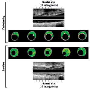
Figure 1. Matched process between preprocedure (below) and post-stent (above) for images of intravascular ultrasound virtual histology. Precise matching was obtained by using vessel landmarks as references for axial location. The stented area was subdivided into 10 sub-segments of equal length. Note the clear increase in the area of necrosis-coded pixels (red) after stenting, especially in the regions surrounding the “added calcium” (metallic struts, in white)
Firstly, the postprocedure IVUS examination was analysed to identify the areas corresponding to the proximal and distal borders of the stented segment. After that, using the vessel landmarks, the preprocedure IVUS was carefully analysed to exactly match the stented segment. Finally, the in-stent segment was divided into 10 sub-segments of equal size, which were considered the basic unit for comparing both baseline and post-stent IVUS-VH images (Figure 1). Each sub-segment unit represents the averaged findings of all cross-sectional IVUS-VH slices falling within that specific sub-segment.
All IVUS-VH analyses were performed off-line by technicians blinded to the patients’ characteristics. For each cross-sectional slice, the luminal and external elastic membrane boundaries were traced semi-automatically and the area measurements for plaque component (fibrous, fibro-fatty, necrotic core, and dense calcium) were obtained utilising a dedicated quantitative software (pcVH 2.2®; Volcano Corporation Inc.). All analyses were performed using averaged areas, to normalise for the different lengths of the stents used.
Post-processing analysis of virtual histology images to quantify the co-localisation of calcium and necrosis
The colour-coded IVUS-VH cross-sections are basically composed of six binary constituents (1-fibrous: dark-green pixels; 2-fibro-lipidic: light-green pixels; 3-necrotic tissue: red pixels; 4-calcium: white pixels; 5-media layer: grey pixels; 6-vessel lumen: internal black pixels) (Figure 2). The decomposition of IVUS-VH images into these discrete elements comprises the basis of the method to quantify the co-localisation of calcium- and necrosis-coded pixels (Figure 2).
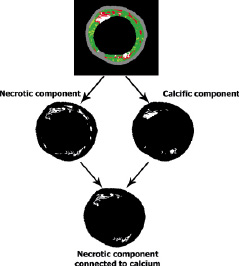
Figure 2. Post-processing analysis of virtual histology images to identify the necrotic component connected to calcium. The original colour-coded cross-section (above) was split into binary images for necrosis (mid, left) and for calcium (mid, right). For each binary converted images, pixels of interest were coded as white and all other structures as black. The lower panel shows the “necrosis-linked to calcium” component, obtained after subtraction of necrosis-coded pixels not connected to calcium-coded pixels.
All original IVUS-VH images were post-processed using to the software Image J, which is an open source image processing plataform built in Java by the National Institutes of Health that provides an environment for Java plugin development, including a broad relation of classes and methods for further applications. A detailed description of Image J is available online (see references).10,11 Specific plug-ins were developed for the analyses presented in this study. The first step of the process was accomplished by splitting the IVUS-VH images into binary images according to the original colour coding (i.e., each one of the four types of plaque components, the media and lumen). For each binary converted images, all pixels were coded as white (pixels originally assigned with the colour of interest) or black (all other colours). Every two neighbors pixels were considered connected according to eight-connectivity, as shown in Figure 3.
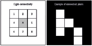
Figure 3. The eight-connectivity scheme is illustrated in the left panel, showing the eight surrounding pixels that are considered to be connected to the middle pixel (in gray). The right panel illustrates an example of a group of pixels considered to be connected according to the eight-connectivity method.
The identification of “necrosis-linked to calcium” pixels was performed by the presence of connected pixels in the binary converted images for necrosis and calcium. The procedure for automatically recognising the connected pixels was called labelling and was based on an identification algorithm, as described by Suzuki et al12. Briefly, this approach consists in a series of alternated forward and backward scans of the previously generated binary images, updating pixel’s labels values according to an equivalence label table. The algorithm stops when the updating of the pixel values is exhausted. In the next step, the connected pixels’ informations (e.g., number of pixels in each island, x-y coordinates) were achieved for future processing. Finally, as IVUS-VH images are bitmaps with contextual information, a calibration procedure was carried out using the total area (in mm2) of each plaque component (available from the original IVUS-VH output file). The unitary pixel area was calculated by dividing the global area of each component by its number of pixels.
Plug-in class structure
As described in the Image J development tutorial, any plugin main class must implement one of the following classes: PlugIn, PlugInFilter, PlugInFrame, or PlugInApplet. Our VH_Plugin attends to this requirement. It automatically performs basic operations such as opening images series and to invoke others methods. VHUtil class is a static class containing three static subclasses: VHUtil.Files, VHUtil.Masking and VHUtil.Stats. In these classes, static methods were implemented to perform different kinds of operations such as VH images binary masking, I/O of frame’s information, and statistics parameters calculations. In the labelling image class, Suzuki’s labelling algorithm was implemented, with its outputs returning to VH_Plugin in LabelStructs objects, where all connected pixels’ parameters were evaluated. FrameInformation and LabelStruct are two classes made to store data generated by the program.
Statistical analysis
Categorical variables are presented as percentages and continuous variables as medians and interquartile ranges. The change between baseline and post-stent in plaque composition was analysed with Paired Wilcoxon test. The association between the change in calcium content and the change in other plaque components was evaluated by linear regression modelling. Analyses were performed with the SPSS 13.0 statistical package (SPSS Inc., Chicago, IL, USA).
Results
Overall, mean age was 58±9 years, seven patients (54%) were men, six (46%) were diabetics, 11 (85%) had hypertension, and four (31%) had previous myocardial infarction. On average, nominal stent diameter was 3.3±0.4 mm, stent length was 16.2±2.8 mm (ranging from 14 mm to 23 mm). From the 17 stents implanted, eight were Apolo (Cordynamic, Barcelona, Spain), 3 were Matrix, Infinnium, or Supralimus (Sahajanand MT, Surat, Gujarat, India), 3 were Chronus (Scitech, Goiania, Goais, Brazil), 2 were Bx Sonic or Cypher (Cordis, Johnson & Johnson, Warren, NJ, USA), and 1 was Pro-kinetic (Biotronik, Berlin, Germany).
Baseline and post-stent IVUS-VH
The whole stented segment was analysed and divided into 10 sub-segments of equal size, carefully matched in baseline and post-stent IVUS runs. On average, the length of each sub-segment was 1.6±0.3 mm.
From this original dataset, matched sub-segments with the lowest amount of necrotic tissue were selected for analysis (cutoff point: median area of necrosis for the whole dataset [<0.55 mm2]).
Baseline and post-stent IVUS-VH findings for the included sub-segments are shown in Table 1.
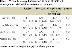
Both the absolute area and the percent component of calcium-coded and necrotic-coded pixels increased from baseline to post-stent. Conversely, the fibrous and fibro-fatty components decreased their area in post-stent images, compared to baseline.
The increase in calcium content between baseline and after stent implantation strongly correlated with the increase in the area of necrosis-coded pixels (R2=0.635; p<0.001) (Figure 4). Conversely the change in dense calcium was not associated with the change in fibro-fatty content or with the change in fibrous area (p=0.6 and p=0.2 respectively) (Figure 4).
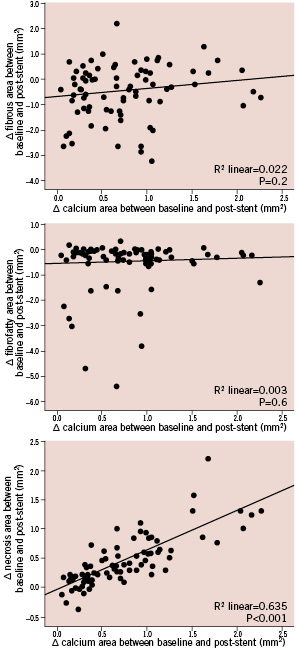
Figure 4. Relationship between the change in calcium content between baseline and after stent implantation and the change in other plaque components. Note that the increase in calcium strongly correlated with the increase in necrosis (lower panel), but was not associated with the change in fibrous or fibro-fatty contents (mid and upper panel respectively).
Post-processing analysis of co-localisation of calcium and necrosis
The area of necrotic pixels spatially connected or not connected to dense calcium is shown in Table 2.
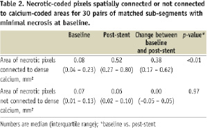
The area of necrotic pixels surrounding pixels coded as dense calcium significantly increased more than 6-fold between baseline and after stenting, while the area of non-connected pixels did not change (Table 2). In fact, the increase in the area of necrosis connected to dense calcium (+0.38 mm2 [0.17 – 0.62 mm2]) (Table 2) virtually explained the entire increase in total necrosis area after stenting (+0.36 mm2 [0.17 – 0.66 mm2]) (Table 1).
The increase in calcium content between baseline and post-stent closely correlated with the increase in necrosis-coded pixels connected to spots of dense calcium (linear R2=0.70; p<0.001) (Figure 5). Conversely, the addition of calcium had no impact on the amount of necrosis not surrounding calcium deposits (Figure 5).
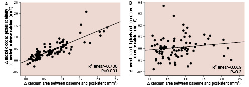
Figure 5. Relationship between the change in calcium content and the change in necrotic pixels connected (left) or not connected (right) to dense calcium. Note that the increase in calcium content between baseline and post-stent closely correlated with the increase in necrosis-coded pixels connected to calcium, while the addition of calcium had no impact on necrosis not surrounding calcium.
Discussion
The main finding of this study was to demonstrate that the addition of calcific elements (i.e., stent struts) to the atherosclerotic plaque led to a directly proportional increase in the area coded as necrosis in virtual histology images. Moreover, the increase in “necrotic tissue” after the addition of “calcium” occurred mostly in pixels surrounding the calcific spots.
It is unlikely that the increase in the necrotic component, detected after stent implantation, could be related to actual necrosis provoked by the metallic struts. Stent implantation has not been previously reported to induce necrosis at the target segment, especially one that is detectable immediately after the implantation and only occurring in the tissue surrounding the struts. Most probably, the “necrotic tissue” detected around the stent struts in our study was related to an artefact produced by the metallic structure of the stent.
The overestimation of necrotic tissue by calcium could be predicted by a linear function (model R2=0.70), indicating that it may be potentially amenable to mathematical correction. Obviously, our study does not aim to provide a means for such correction. Indeed, our findings only suggest that some necrosis-coded pixels connected to calcium may actually not correspond to necrosis, but no alternative method is proposed to ascertain to which tissue component the pixel should be allocated. We believe that our results should encourage the manufacturer to improve the classification algorithm in order to better categorise tissue components in a more accurate manner, as well as other common features not included so far in the virtual histology output, such as struts, thrombus, and blood.
Previous studies have already detected that the amount of necrotic tissue should be adjusted for the area of calcification in order to improve the association between IVUS-VH and clinical features.4 Our findings are in line with these early studies, and, indeed, expand the understanding of the need for a correction factor, as well as a method to calculate it.
The present study has several limitations that should be highlighted. The sample size was small, thus our results should be viewed more as hypothesis-generating than as of conclusive nature. Moreover, the utilisation of stent struts to imitate calcium restricted this simulation to small “artificial” calcific spots. Therefore, our findings cannot be extrapolated to larger calcification areas. Moreover, it must be acknowledged that stent struts are not calcific elements. In fact, although simulating calcium, the metallic stent structures are indeed not recognised as such by the classification tree of IVUS-VH.
Conclusions
Artificial addition of calcium-like elements to the atherosclerotic plaque led to an increase in necrotic tissue in IVUS Virtual Histology that is probably artefactual. The overestimation of necrotic tissue by calcium followed a linear pattern, indicating that it may be amenable to mathematical correction, which may potentially enhance the diagnostic accuracy of the method.