Abstract
Coronary obstruction is a life-threatening complication of transcatheter aortic valve replacement. Bioprosthetic or native aortic scallop intentional laceration to prevent iatrogenic coronary artery obstruction (BASILICA) seems to be an effective approach for preventing coronary obstruction by maintaining blood flow towards the coronary artery by an intentionally created leaflet laceration. In this report, we aimed to provide step-by-step guidance on how to perform a BASILICA procedure. The technique includes several steps that can be challenging without proper guidance. Assistance by operators who have already performed BASILICA seems to be crucial, and formal proctorship during initial procedures can ensure good clinical outcomes.
Abbreviations
| BASILICA | bioprosthetic or native aortic scallop intentional laceration to prevent iatrogenic coronary artery obstruction |
| TAVR | transcatheter aortic valve replacement |
| THV | transcatheter heart valve |
| VTC | virtual transcatheter heart valve to coronary distance |
Introduction
Coronary obstruction is a life-threatening complication of transcatheter aortic valve replacement (TAVR)1,2 (Figure 1). The incidence of coronary occlusion is approximately 0.5% in native aortic valve TAVR and 2-3% in aortic valve-in-valve (ViV) TAVR1,3. Patients identified as being at risk of coronary obstruction with TAVR were historically sent to high-risk open heart surgery or were treated with medications alone, with poor prognosis. Transcatheter techniques to prevent coronary obstruction included deploying a stent to deflect the leaflet from the coronary artery ostium inflow. Unfortunately, this chimney/snorkel technique may be limited by acute complications, poor coronary flow durability and challenges in reintervention in the coronary vasculature (Figure 1). Bioprosthetic or native aortic scallop intentional laceration to prevent iatrogenic coronary artery obstruction (BASILICA) utilises “catheter electrosurgery” techniques previously employed in other procedures4,5. BASILICA was first performed in July 2017 at the University of Washington in Seattle and in the following 18 months was performed in more than 150 patients worldwide. It seems to be an effective approach for preventing coronary obstruction by intentional leaflet laceration6,7. In this report, we aimed to provide step-by-step guidance on how to perform a BASILICA procedure.
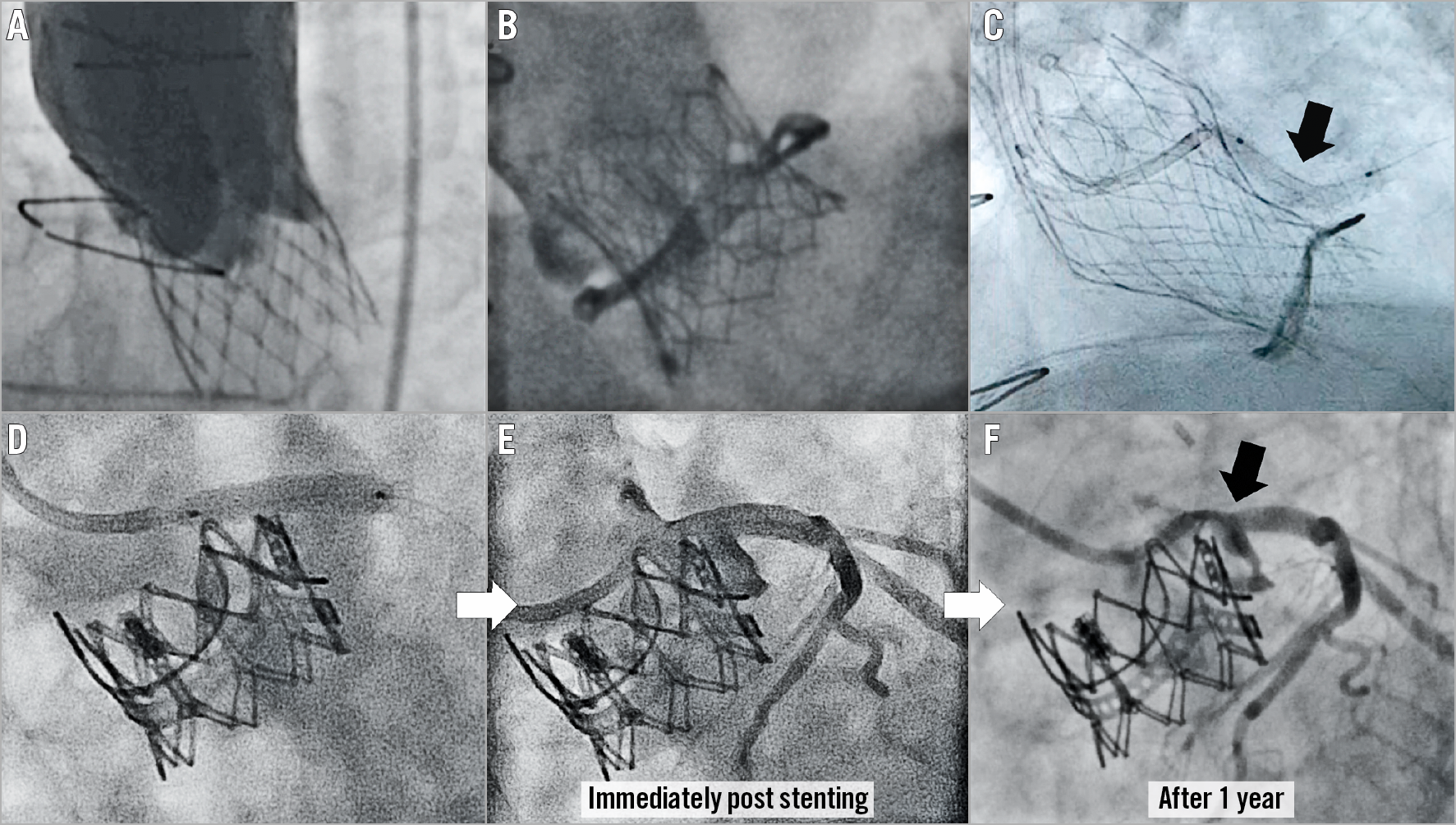
Figure 1. Case examples of coronary obstruction after TAVR, and prevention by stent implantation with delayed obstruction. A) & B) Coronary obstruction following transcatheter aortic valve replacement (TAVR) using a CoreValve® (Medtronic, Minneapolis, MN, USA) in a Toronto® stentless porcine valve (SPV) (St. Jude Medical, St. Paul, MN, USA) (A) and a SAPIEN 3 (Edwards Lifesciences, Irvine, CA, USA) in a Mitroflow (Sorin Group Inc., Saluggia, Italy) (B). C) Prevention of coronary obstruction using the chimney/snorkel technique in which a stent is pre-positioned undeployed in the coronary tree during TAVR to be deployed after valve deployment in the coronary inflow, to deflect the aortic valve leaflet (arrow). D) - F) Delayed coronary obstruction after the chimney/snorkel technique for left coronary obstruction (E) after SAPIEN XT in Magna (both Edwards Lifesciences) aortic valve-in-valve (D).
THE BASILICA CONCEPT
BASILICA directly addresses the pathophysiology of coronary artery obstruction by lacerating the leaflet in front of a threatened coronary artery (Figure 2). The concept of BASILICA is that a sliced leaflet will splay after TAVR and create a triangular space (“triangle of flow”) that may permit blood flow towards the sinus and from it to the coronary artery, which otherwise would have been occluded. The potential advantage of BASILICA over coronary stent protection is that it directly addresses the cause of the adverse event, the valve leaflet. In addition, it may result in easier coronary access after TAVR and does not leave additional material in the aortic root (such as coronary stents). The key steps of the BASILICA procedure are demonstrated in Figure 3 and Moving image 1.
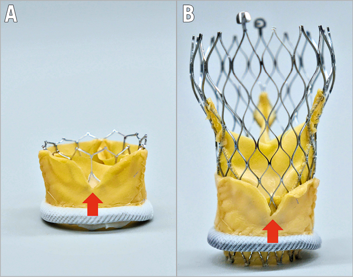
Figure 2. Bioprosthetic or native aortic scallop intentional laceration to prevent iatrogenic coronary artery obstruction (BASILICA). The red arrows show the gap of the lacerated leaflet. Through the leaflet gap, flow to the coronary sinus could be maintained (triangle of flow). BASILICA with SAPIEN 3 (A) and Evolut™ R (Medtronic) (B) valves in a Mitroflow.
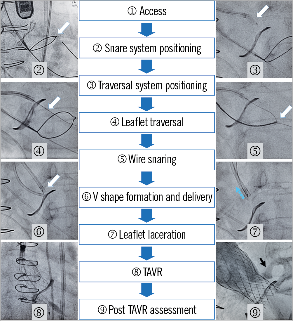
Figure 3. BASILICA procedure steps.. Each stage is presented using a case example of left BASILICA for a failed Mitroflow valve with Evolut R valve-in-valve implantation. The white arrows indicate each step. The blue arrow (stage 7) indicates the direction of leaflet laceration. The black arrow (stage 9) indicates coronary artery flow after TAVR.
Adverse events related to the BASILICA procedure include haemodynamic instability related to aortic regurgitation after leaflet laceration and potential thromboembolism related to manipulations of diseased coronary cusps. Wire electrification may also potentially cause an injury to adjacent tissue and arrhythmia. Importantly, although BASILICA seems to reduce the risk of coronary obstruction significantly, it does not eliminate that risk.
A precise patient selection for BASILICA is yet to be defined. Certain parameters, such as very low coronary take-off, narrow sinuses, short virtual transcatheter valve to coronary ostium distance (VTC) and ViV for stented bioprosthetic surgical valves with externally mounted leaflets or stentless valves, are suggested to increase the risks of coronary obstruction. Several of these types of patient may be candidates for BASILICA8.
Contraindications for BASILICA are yet to be described; however, it is conceivable that some anatomical characteristics, such as VTC ~0 mm and unusually calcified native or bioprosthetic valve leaflets in patients, would not allow a successful BASILICA. A combination of an extremely low coronary artery height with too narrow a sinus can be a contraindication because the skirt of a new transcatheter heart valve (THV) itself could potentially occlude the newly formed “triangle of flow”. In addition, considering the procedural steps, obvious thrombus formation, mobile structures in the target leaflet and cases with suspected endocarditis should be excluded. Notably, haemodynamic changes due to suddenly created aortic regurgitation after laceration need to be anticipated, especially in patients with very low cardiac output and significant coronary artery narrowing. Therefore, severe coronary artery disease should be treated in advance since it may intensify haemodynamic instability once acute regurgitation occurs.
Equipment and preparation
A complete list of items required for BASILICA is shown in Figure 4. BASILICA must be performed in a room with wide availability of percutaneous coronary intervention tools since these can be required acutely. Both general anaesthesia and conscious sedation can be considered for BASILICA. However, because of the risk of haemodynamic deterioration after the laceration, and the benefit of transoesophageal echocardiography (TEE) in guiding the direction of wire traversal, in addition to evaluating unclear traversed wire positions, it is recommended to start a centre experience with general anaesthesia and an experienced echocardiographer. Other than conventional TAVR equipment, there are several equipment components that are not commonly utilised: these include a snare, Astato XS 20 300 cm (Asahi Intecc USA, Inc., Tustin, CA, USA), PiggyBack® Wire Converter (Vascular Solutions, Minneapolis, MN, USA), 8 Fr guide catheter for the traversal system and a 125 cm diagnostic 5 Fr internal mammary (IM) catheter. The back of the Astato wire should be carefully scraped for about 3-5 cm using a scalpel blade until the metal part of the wire is exposed, followed by a solid direct connection of the metal part with an electrical pencil by grabbing them with a mosquito clamp (Figure 5). The blades of certain types of surgical pencils are covered by rubber, which should be scraped before connection. Attention should be paid that none of the circuit is touching the other metal to avoid electricity loss during electrification. The Astato wire should be kept dry inside the PiggyBack. Manipulation of the lock system of the PiggyBack is shown in Figure 6. Since the C-arm angles used during BASILICA are commonly steep, it is sometimes challenging to obtain good resolution fluoroscopic images; therefore, it will be easier to mark the length of the 5 Fr long IM catheter where it reaches the end of the 8 Fr guiding catheter. Using an 8 Fr guiding catheter for the traversal guide instead of a 6/7 Fr seems to improve manipulation of the IM and a reliable contrast injection through the 8 Fr while the IM is inside it to depict the target position. The electrosurgical generator is set on “pure cut” mode and the power is set according to the leaflet character. In our practice this includes: 30W for traversal of a porcine valve, 50W for a bovine or native valve, and 70W for a severely calcified leaflet; also, 50W for laceration of a porcine valve, 70W for a bovine or native valve, and 100W for a severely calcified leaflet. There is limited clinical experience of using substitutes for the Astato XS 20 and PiggyBack; the utility of other wires or microcatheters is yet to be proven. However, there are several potential advantages of using the PiggyBack. These include, but are not limited to, the lock system that secures the Astato wire kink position during laceration.
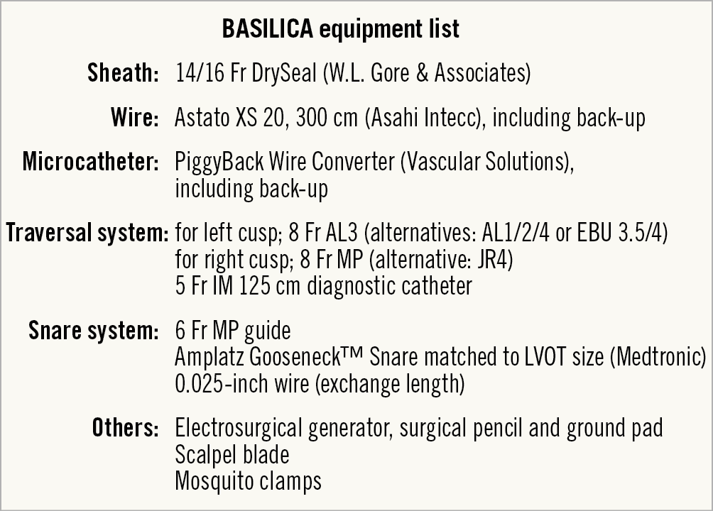
Figure 4. Equipment list for a BASILICA procedure.
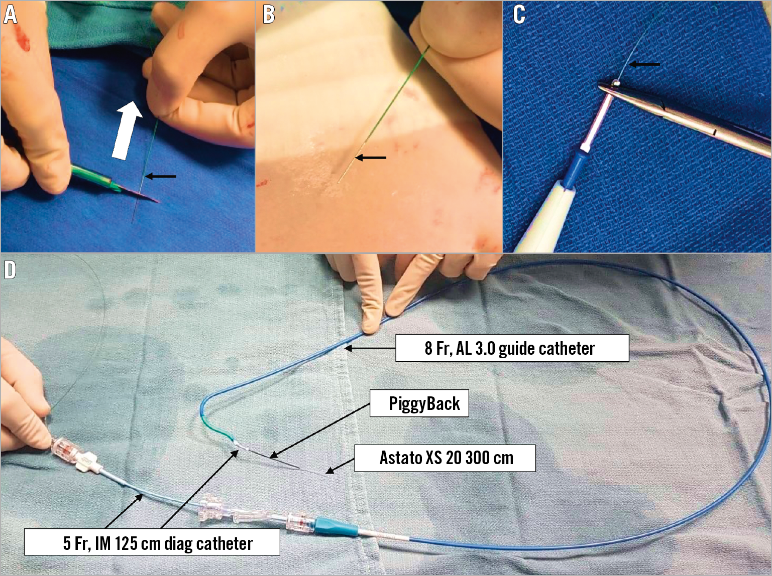
Figure 5. Table preparation of the traversal system. A) & B) The distal end of the Astato XS 20 300 cm wire is shaved (white arrow) with a scalpel (black arrow). C) The wire is connected with a haemostat to the electrosurgical unit pencil (black arrow). D) The Astato XS 20 wire is positioned inside the PiggyBack microcatheter. Both are inserted into the IM diagnostic catheter through a COPILOT. In this picture, the IM is loaded and inserted into the traversal guide (a step that occurs inside the body).
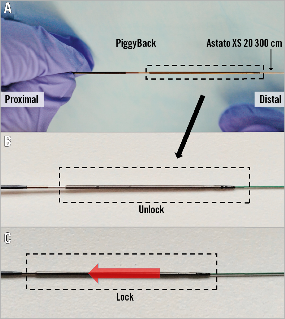
Figure 6. Locking of the PiggyBack microcatheter over the Astato XS 20 wire which is inside it. This manoeuvre allows fixing the relationship between the “V-shape” of the wire and the microcatheter. The PiggyBack should be unlocked until the wire kinking step. After that step, the PiggyBack should be locked and kept in this mode throughout the procedure. A) PiggyBack lock system, B) unlocked position and C) locked position.
BASILICA procedure steps
ACCESS
Many patients at risk of coronary obstruction have both narrow aortic roots and small peripheral vessels. It is therefore not surprising that many candidates for BASILICA require alternative access. A leaflet that requires BASILICA needs a loop of two guide catheters: a traversal catheter (commonly 8 Fr) and a snare catheter (commonly 6 Fr) (Figure 7A). The 8 Fr traversal catheter could be delivered through a large sheath to be utilised later for TAVR. For a rapid shift to THV implantation after leaflet laceration, the large sheath should include a pigtail, in parallel to the traversal guide, to be positioned in the left ventricle just before leaflet laceration. The Gore® DrySeal sheath (W.L. Gore & Associates, Inc., Flagstaff, AZ, USA) is the most commonly used sheath in BASILICA procedures since it allows insertion of several catheters through it without leaking. A radial artery can be used as an arterial line for blood pressure monitoring as in all high-risk procedures. In addition, a 6 Fr sheath could be utilised in the right radial artery for a cerebral protection device (e.g., Sentinel™; Claret Medical, Santa Rosa, CA, USA).
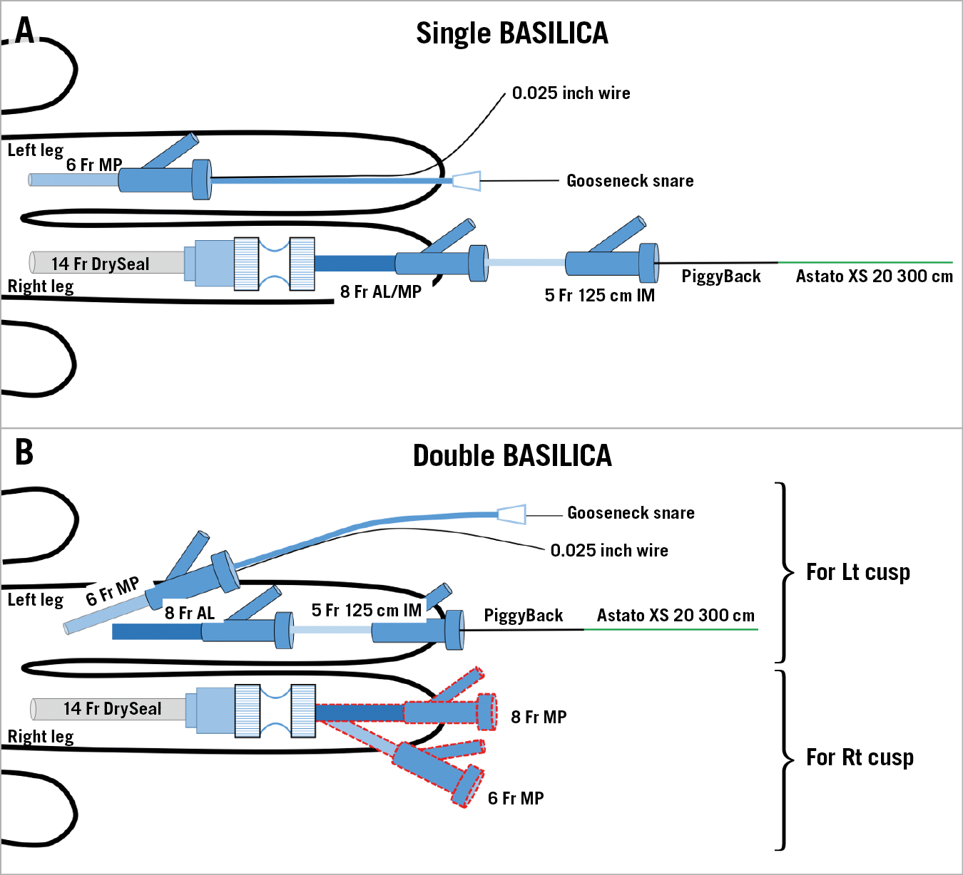
Figure 7. Access in BASILICA procedures. For single BASILICA (A), a 6 Fr MP in the left femoral artery for the snare system and a 14 Fr DrySeal in the right femoral artery for the traversal system. An 8 Fr AL is used for the left coronary cusp BASILICA and an MP is used for the right coronary cusp BASILICA. For double BASILICA (B), double access with 6 Fr and 8 Fr in the left femoral artery is obtained for left cusp BASILICA. After delivering the wire V-shape on the left leaflet, catheters for right cusp BASILICA are inserted through the DrySeal. An alternative for double BASILICA can include a large sheath in each groin.
For double (two leaflets) BASILICA, to avoid prolonged exposure to massive aortic regurgitation, leaflet laceration should be performed without delay. Since each BASILICA requires two catheters, four catheters should be utilised at the same time. One example for the access would be a 14 Fr DrySeal in one side (holding two catheters inside in parallel – traversal catheter and snare catheter) and a double puncture of a 6 Fr and an 8 Fr sheath in the contralateral femoral artery (Figure 7B). Alternatively, a double 14 Fr DrySeal (each holding two catheters in parallel) can be considered; however, the risk of bleeding and vessel complication may increase while using this double large sheath approach. Leg ischaemia by a large bore sheath during the potentially prolonged procedure should be watched for and, in general, large sheath time in the groin should be minimised.
SNARE POSITION
After crossing the aortic valve, the catheter is exchanged with a 6 Fr Multipurpose (MP) guiding catheter (a 6 Fr JR4 can be substituted in severely angulated roots). Subsequently, a 0.025-inch curved wire is delivered to the left ventricle apex. This wire allows redirecting the snare guide to the left ventricle (LV) when the guide is pulled out of the ventricle. This will also support snaring manipulations to facilitate easy snare guide reinsertion. After that, a snare is advanced through the guide into the left ventricular outflow tract (LVOT) in parallel to the 0.025-inch wire. The snare size is determined by the perimeter-derived diameter of the LVOT at 5-10 mm below the annulus plane. Between two optional snare sizes we commonly select an undersized snare since too large a snare does not form well in the LVOT. However, too small a snare will not grab the traversed wire unless the attack angle of the traversal system is sufficient. The optimal snare position is viewed as close to a straight line in the LVOT in both cusp front and side projections. Occasionally, the snare is entangled with the 0.025-inch wire, preventing normal formation. The snare should be placed 5-10 mm below the aortic annulus to have a good marker for traversal and to achieve easier snaring after leaflet traversal (Figure 8).
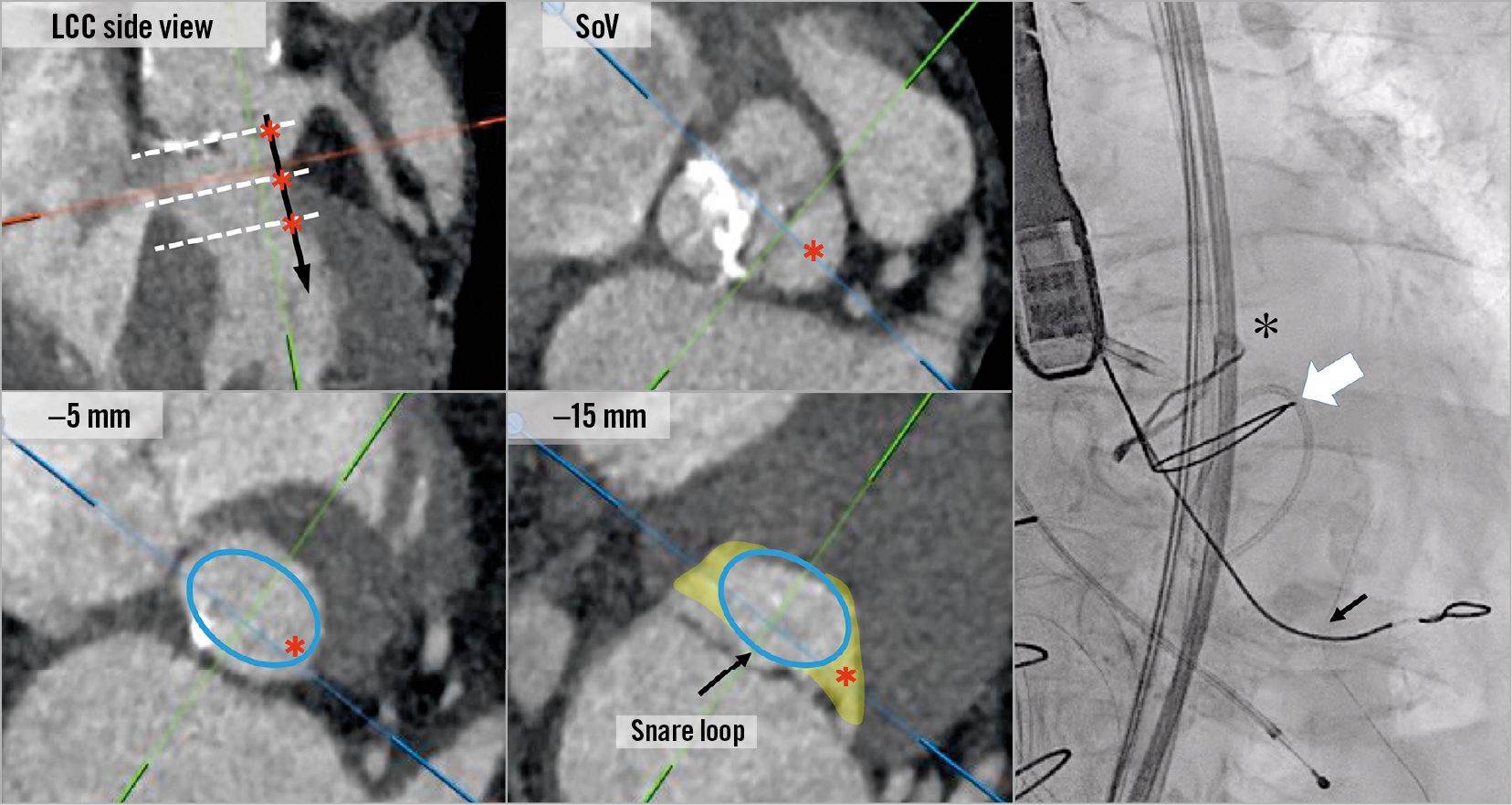
Figure 8. Snare position in the left ventricular outflow tract (LVOT). An illustration of the potential path of the traversal wire (black arrow and red asterisks) after crossing the leaflet at the sinus of Valsalva (SoV), –5 mm and –15 mm level (white dotted lines) showing how the LVOT becomes very elliptic deep in the ventricle and how a snare may not be successful if positioned too low. Optimal snare position should be viewed as a straight line along the LVOT and up to 10 mm below the annulus plane. The right picture is an example of an ideal snare position (white arrow) of BASILICA for Mitroflow (black asterisk). The black arrow shows the 0.025-inch support wire.
LEAFLET TRAVERSAL
Leaflet traversal is commonly the most technically demanding step of the BASILICA procedure. This is a step that also dictates the ability to snare the wire and, most importantly, the efficacy of BASILICA. The traversal system includes a telescope of devices aiming to direct the traversal wire (Astato XS 20 300 cm) towards the mid base of the target cusp. The traversal guide is an 8 Fr guide that allows reaching the base of that target cusp. For left cusp BASILICA, an AL3 is currently the most commonly used guide; however, AL1, AL2, AL4 and EBU 3.5 and EBU 4 have also been utilised. Guide selection is influenced by the size of the ascending aorta and the angulation of the root. However, the target of the traversal guide is not the coronary artery but the base of the cusp; therefore, the guide is commonly severely oversized. For right coronary BASILICA, MP guides are commonly utilised and JR guides are potential substitutes. Cusp injection through the traversal catheter can provide better understanding of traversal guide positioning. Ideally, the target leaflet should be projected in two angles (“front view” and “side view”) to evaluate and ascertain an accurate traversal system position. These projections are predetermined by CT before the procedure8. Left cusp “front view” and especially right cusp “side view” are usually in extreme projections.
When the traversal guide is in a good position, then the combination of a 5 Fr long IM with an Astato XS 20 in the PiggyBack inside it is advanced through the traversal guide. At this point, manipulation of the traversal guide and the IM is performed while viewing the optimal relationship with the leaflet in both “front view” and “side view”. The aim is to achieve a relationship with optimal leaflet orientation, height and attack angle (Figure 9). Suggested catheter manipulations to obtain an ideal position are illustrated in Figure 10. It is crucial to verify an optimal attack angle towards the leaflet since wire traversal can be eccentric towards one of the cardiac chambers, through the aorta, or towards the coronary artery (Figure 11). The attack angle is viewed in side view projection of the leaflet. If the side view projection is not achievable, then biplane and/or TEE can be utilised to verify the direction of the traversal system. Catheter manipulation should be performed carefully, in particular to avoid coronary artery ostial dissection and injury to fragile porcine leaflets. Rotation direction in each front and side view is important for successful positioning (Figure 10).
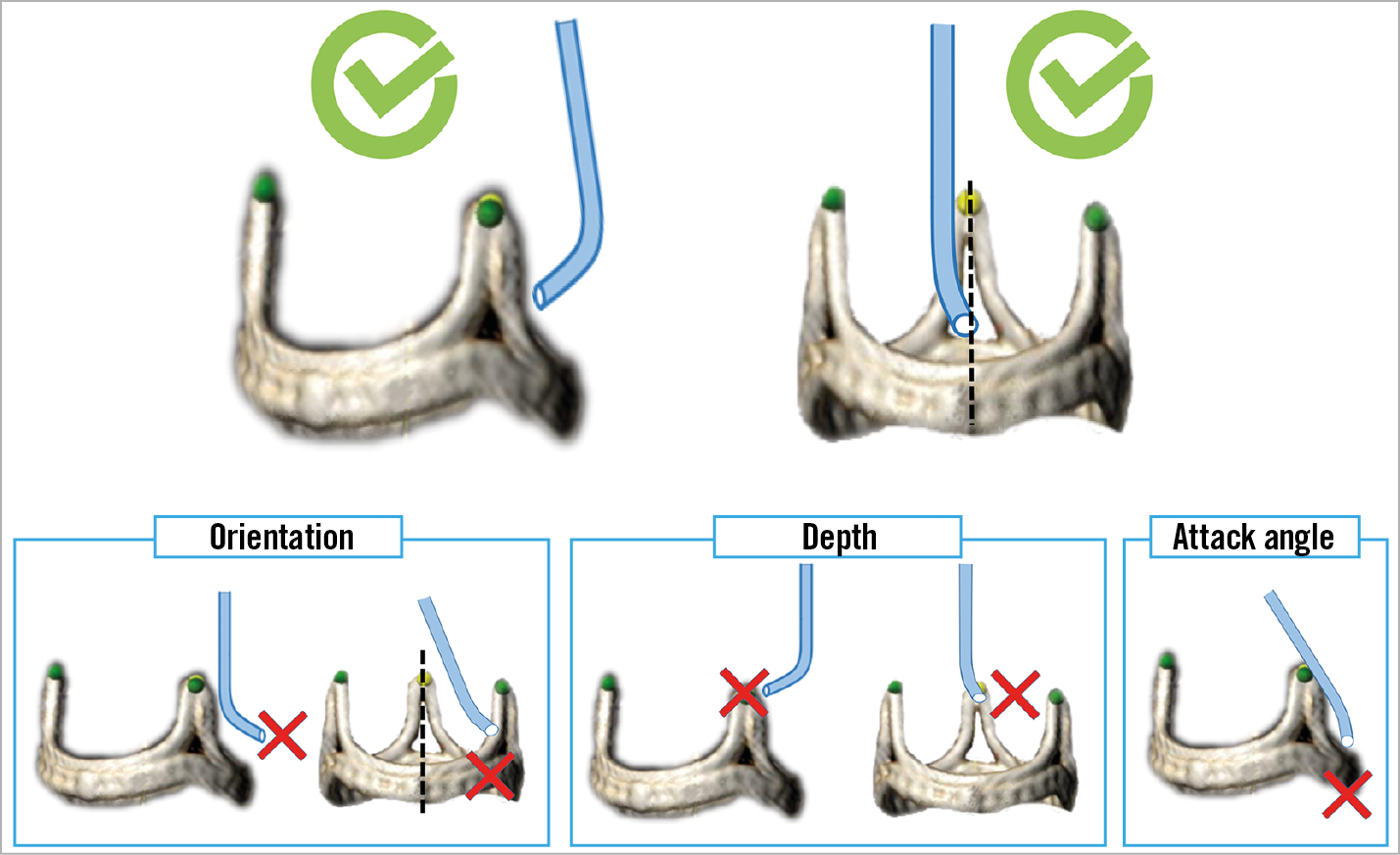
Figure 9. Illustrations of three requirements for optimal traversal system positioning: orientation, depth and attack angle. Both “front view” and “side view” projections are needed for these assessments.
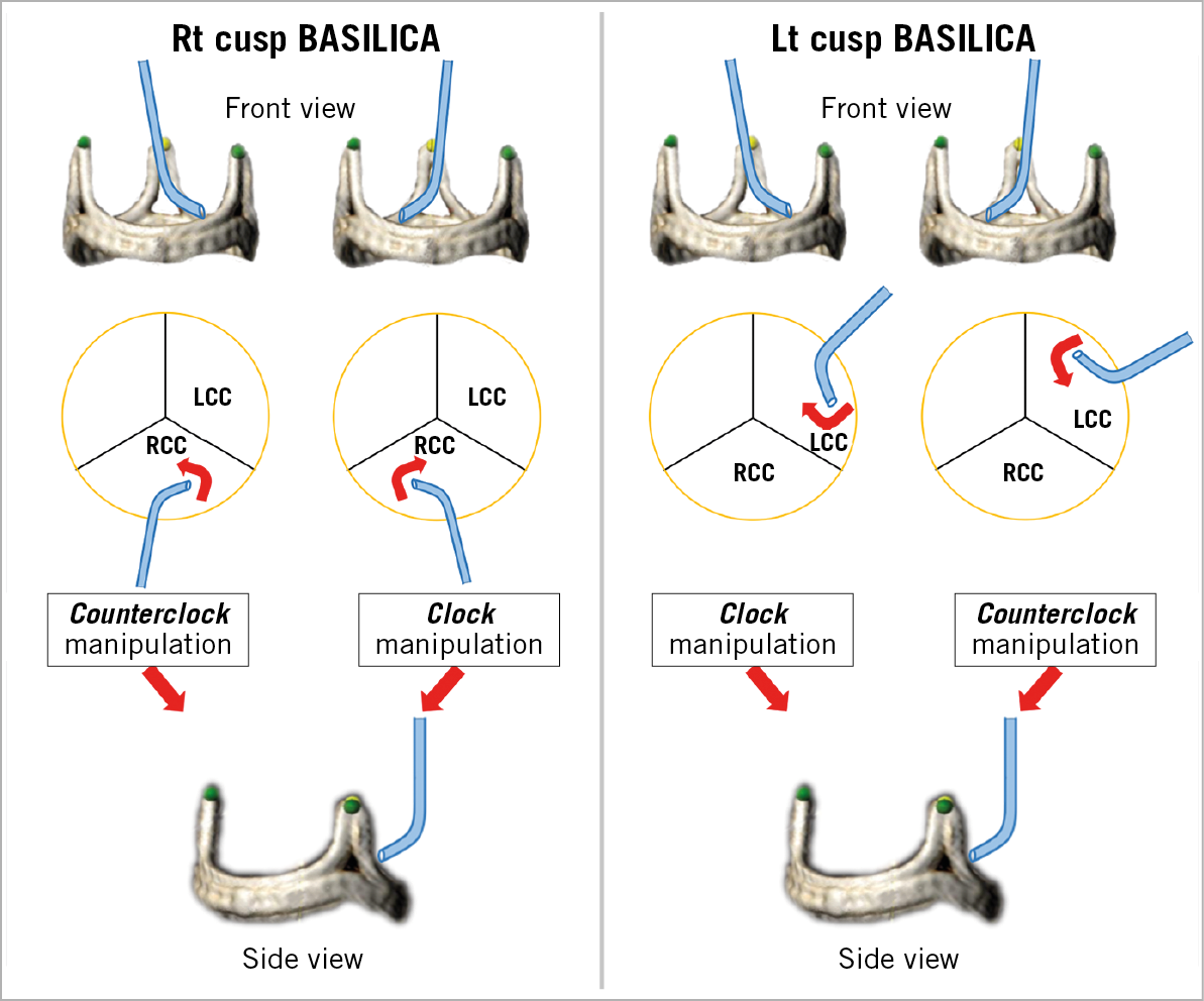
Figure 10. Illustration of traversal system required manipulations to achieve the optimal “attack angle” in front view projection. After adjusting the depth, rotate the catheter clockwise or counter-clockwise to orient the catheter as shown (red arrow). Be advised that in certain anatomical conditions these described manipulations may not be performed accurately. LCC: left coronary cusp; RCC: right coronary cusp
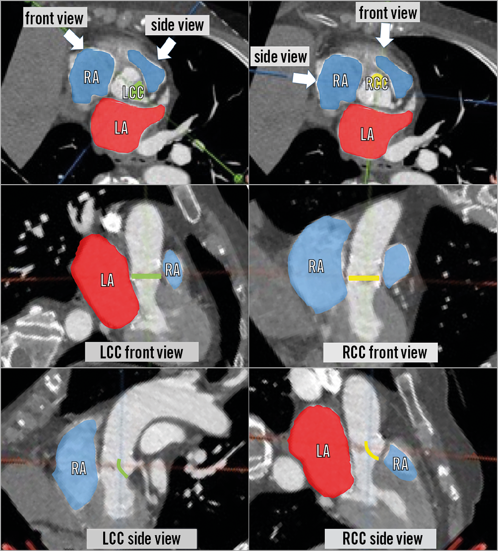
Figure 11. Relationship between different cardiac chambers and the left cusp (left panels) and right cusp (right panels). Left coronary cusp (LCC) (green) and right coronary cusp (RCC) (yellow) and each front and side view. Red areas indicate left atrium (LA) and blue areas indicate right atrium (RA) and right ventricle. Left cusp vertical traversal may lead to perforation of the aorto-mitral curtain and crossing to the left atrium. Right cusp vertical traversal may lead to perforation of the interventricular septum.
Once positioning is confirmed in both projections for attack angle, orientation and height, then the operator is set for leaflet traversal (Figure 9). Before traversal, make sure to advance the tip of the PiggyBack to be very close to the target leaflet. The traversal projection should be the side view since this will ensure that the catheter is not pointing towards the aortic wall. Electrification under “pure cut” mode should be very brief (less than a second) and paused immediately after the wire crosses the leaflet, or if the wire starts to buckle. In a case of failed traversal, make sure that the circuit is adequately made without touching any other metal or liquid. TEE images can sometimes depict the effect of the burn with notification of bubbles in the aorta. Wire traversal can cause ventricular tachycardia (VT)/ventricular fibrillation (VF), and the team should be ready for cardioversion if necessary. A wire traversal example under benchtop testing is shown in Figure 12.
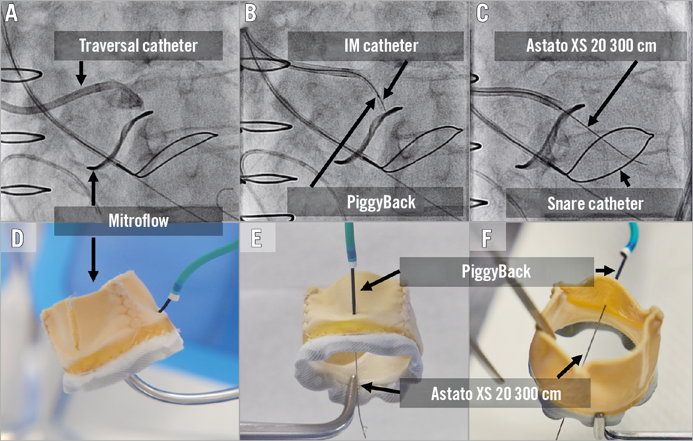
Figure 12. Wire traversal. A) - C) Left cusp traversal of a Mitroflow valve. Traversal system includes 8 Fr AL guide, 5 Fr IM diagnostic catheter, PiggyBack microcatheter and Astato XS 20 wire. The snare system includes a 6 Fr MP guide, a gooseneck snare and 0.025-inch wire. An optimal attack angle (trajectory towards the LVOT snare) and depth in side view (B). D) - F). Bench testing showing Mitroflow leaflet traversal.
WIRE SNARING
When the traversal system is positioned optimally, the traversed wire is commonly already inside the snare loop and wire snaring is intuitive. Occasionally snaring the traversed wire is time-consuming. Snaring manoeuvres include shifting to an acute projection that shows where the wire is missing the snare, changing snare position and then pulling the Astato above the snare plane and pushing down again. Snaring must be performed high in the LVOT to avoid any injury to the mitral valve apparatus. If snaring is not successful, then TEE can help identify whether the wire is indeed in the LVOT. Lack of attack angle can easily deliver a left cusp traversed wire through the aortic-mitral curtain towards the left atrium and, when performed for the right cusp, through the interventricular septum (Figure 8, Figure 9, Figure 11). Potential manoeuvres for challenging snaring include: changing snare size and/or snare guide type, crossing the leaflet with the PiggyBack and reinsertion of a curved Astato wire and attempting to traverse the leaflet again in a different position and/or using different attack angles. Once snaring is achieved, the operator delivers the snare guide through the aortic valve towards the LVOT (unless it is already there), removes the 0.025-inch anchoring wire, and subsequently pulls the Astato wire inside the snare guide by pulling the snare. The wire should be kept in the ascending aorta and not snared out of the body to prepare for the next step - creating the wire V shape (Figure 13).
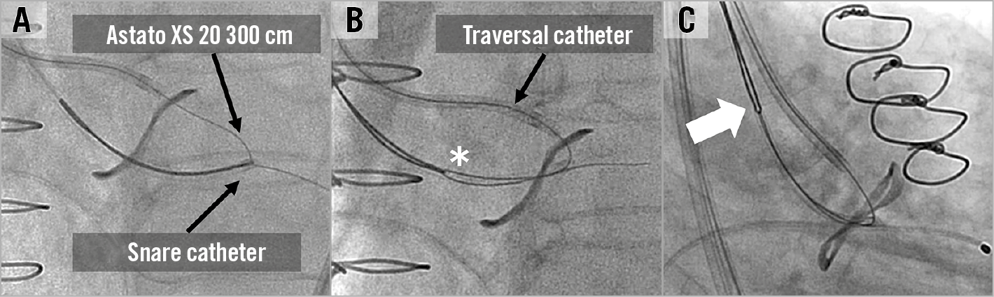
Figure 13. Wire snaring. A) The Astato XS 20 300 cm wire is snared in the LVOT and the snare catheter is inserted to the LVOT. B) The 0.025-inch wire is removed, and the wire is invaginated inside the guide. C) The snared wire is brought back to the ascending aorta. At this point the wire is not snared out of the body until the wire “V-shaping” is finalised.
WIRE V SHAPING
The method of leaflet laceration is by pulling an electrified kinked (V-shape) and denuded Astato through the target leaflet. Both sides of the Astato should be out of the body to enable the pull of the leaflet laceration. The V-shape should be performed in the middle part of the wire, which is covered by the PiggyBack and long IM catheter. Therefore, the first step is to remove parts of the traversal system that cover the Astato wire. This requires removing the IM out of the body and bringing the PiggyBack to the back of the wire with ~10-20 cm spare, to be connected to the electrification pencil later. At this point, the back of the PiggyBack is turned into the locked position to guarantee a fixed relationship between the microcatheter and the V-shape. Usually this is the first and only time that the locking mechanism of the Piggyback is utilised. The V-shape is created by denuding the Astato wire approximately 10 mm just as it exits from the microcatheter and only one part of the wire circumference. The wire is scraped by a blade and bent in such a fashion that the denuded part is in the inner curve of the V-shape (Figure 14). The V-shape needs to be delivered with the PiggyBack through the bleedback control valve (such as COPILOT; Abbott Vascular, Santa Clara, CA, USA) system of the traversal guide. This is commonly done by removing the COPILOT from the guide and pulling the V-shape from the other side. At this point the V-shape is delivered towards the leaflet while the snare is pulling the Astato wire from the other side.
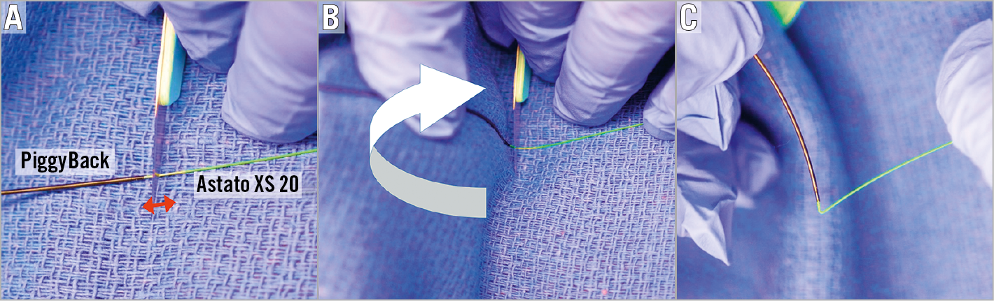
Figure 14. Wire V shaping. A) After the PiggyBack is locked, the wire is denuded ~10 mm just distal to the PiggyBack exit (red arrow). Denuding includes only one side of the wire. B) The wire is intentionally kinked into a V-shape in such a way that the denuded portion is in the inner curve of the kink (white arrow). Typically, the non-sharp side of a scalpel blade will be located on the mid part of the denuded position followed by wire bending, using a towel which is put underneath the wire. C) Created V shape showing the required acute “V” angle.
LEAFLET LACERATION
Before leaflet laceration, the operator should confirm that all the equipment tools for TAVR are ready in order to move quickly towards implantation, since haemodynamic instability related to aortic regurgitation can occur. A pigtail catheter should be inserted towards the LV through the large sheath which may allow rapid TAVR after leaflet laceration (Figure 15). Current practice does not support leaving the stiff wire in position to avoid interaction between this wire and the Astato when electrified. The position of the laceration system must be verified: the two guides should be positioned close to the leaflet while the V-shape should be positioned exactly inside the leaflet. Before laceration, the operator should adjust the wire position to release all slack. Haemostats or wire torquers should be positioned behind the COPILOT to ensure that the wire will not be pulled inside the guides when the guides are pulled back during laceration (Figure 16). The arterial sheaths holding the laceration catheters should be sutured in (alternatively, assistant operators can hold the sheaths during laceration). The electrosurgical pencil should be connected to the Astato wire at the back of the PiggyBack. Laceration is performed by turning on the electrosurgery unit and pulling both haemostats/torquers that hold each end of the Astato wire. At the same time, attention should be paid to pull the catheters as well. Laceration must not be aggressive as this can avulse the leaflet. The pull should be with moderate tension alone. Aggressive pulling can also dislodge the pigtail from the left ventricle, the Sentinel system or the coronary protection guide, if utilised. A benchtop test example of leaflet laceration is shown in Figure 17. Simultaneous pure dextrose injection in each guide catheter was commonly performed in the first cohort of BASILICA procedures; however, its importance is not yet clear. If dextrose is not utilised, the two catheters must be well flushed before leaflet laceration in order to remove all blood content from the guides. Following laceration, haemodynamic instability related to regurgitation when it occurs needs to be evaluated and treated with inotropic support and gentle rapid pacing. The laceration system needs to be removed by releasing the Astato wire from the snare guide COPILOT end and pulling it out of the body by pulling the PiggyBack out of the body while making sure that the Astato is pulled well from the other side. Occasionally, removal of a kinked part of the wire requires some manipulation.
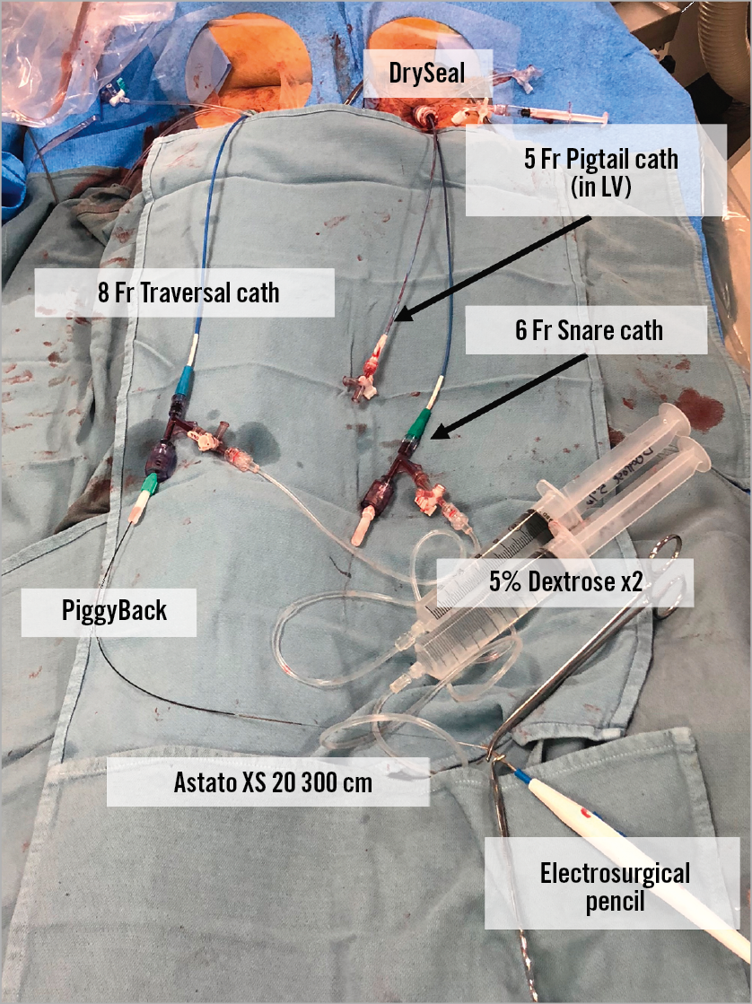
Figure 15. An example of the table immediately before leaflet laceration. A pigtail catheter is put in the LV just before the leaflet laceration. In this case, an 8 Fr catheter was inserted in the right femoral and a 6 Fr snare catheter was placed via a DrySeal sheath. The Astato XS 20 wire in the 6 Fr snare catheter is held with a 0.014-inch compatible torquer and the PiggyBack catheter inserted from the right side is held with a 0.035-inch compatible torquer.
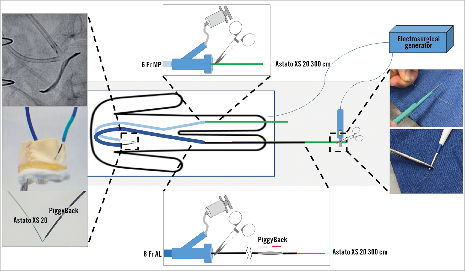
Figure 16. Table and catheter settings before leaflet laceration. The wire V-shape is positioned inside the leaflet with the PiggyBack and catheters close to it to maximise the conductivity. The Astato XS 20 in the left side and PiggyBack in the right side are locked with mosquito clamps.
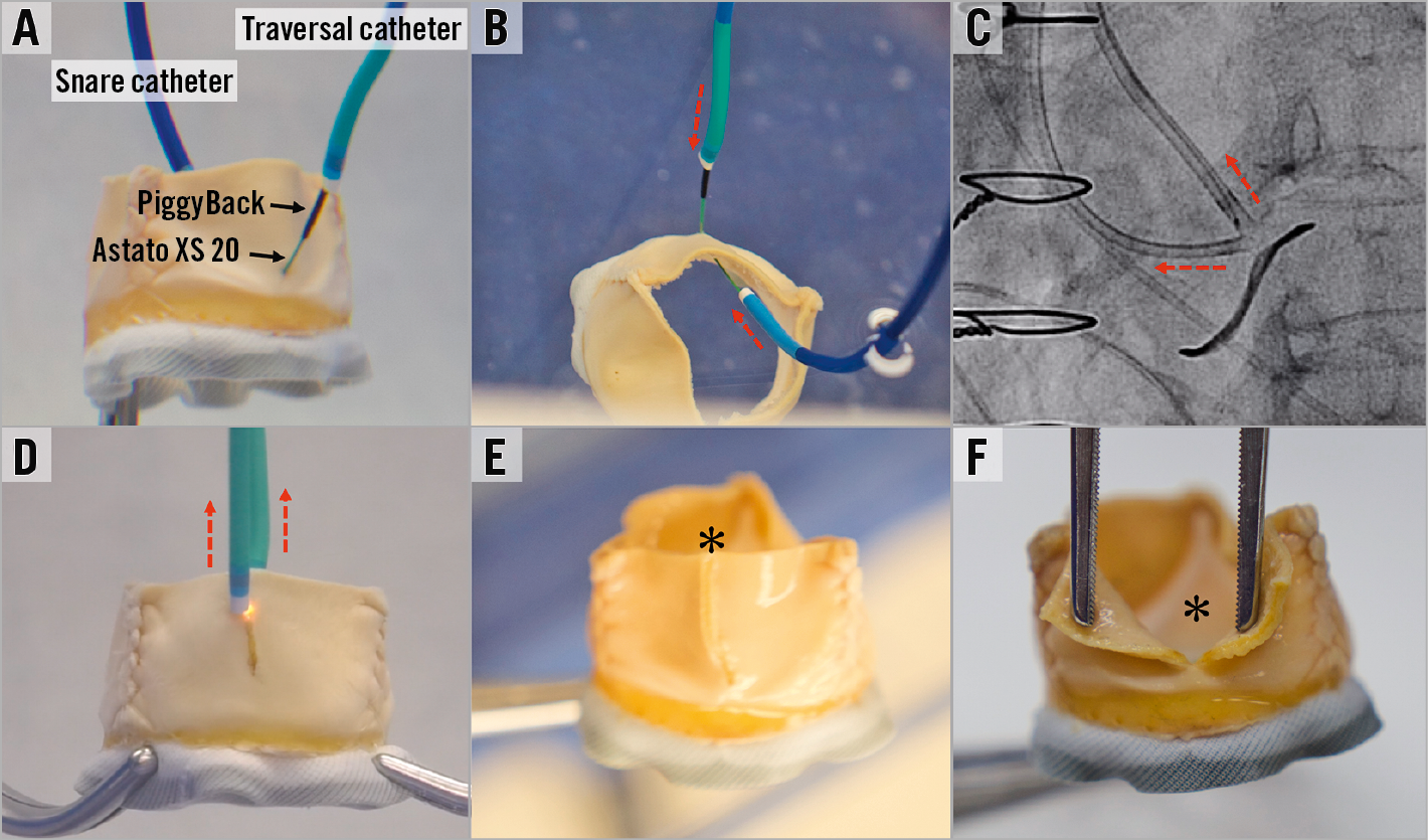
Figure 17. Leaflet laceration. A) A benchtop evaluation of a Mitroflow showing the position of the snare catheter and the traversal catheter with PiggyBack and Astato XS 20 inside it. B) Before laceration, both traversal and snare catheters should be brought close to the V-shape. C) & D) Lacerating by turning on the electricity and pulling the catheters and wire ends (dotted red arrows). E) & F) Centreline laceration of a Mitroflow. Black arrows indicate PiggyBack and Astato XS 20 wire. Black asterisk indicates lacerated leaflets.
TAVR AND POST-IMPLANTATION ASSESSMENT
TAVR post BASILICA should be performed with minimal delay after leaflet laceration. To date, most BASILICA procedures have been performed without coronary protection. However, in cases where the risk of coronary obstruction seems to be high even after the BASILICA or when there is a borderline risk in a non-BASILICA coronary artery, then coronary protection should be considered. Consideration of THV position should include the potential coverage of the device skirt or commissure of the BASILICA “triangle of flow”. Our ability to control anatomical positioning of THV devices (not having the commissure of the THV in front of the coronary artery, or BASILICA triangle) is unfortunately limited with most THV devices. Implant depth should not be too high in cases where the device skirt can cover the leaflet gap caused by the BASILICA; however, this consideration should be balanced against the risk of elevated gradients with too low a position. Post-dilatation and bioprosthetic valve ring fracture should be approached very cautiously in BASILICA procedures since these can cause coronary obstruction. After TAVR, any haemodynamic instability should be considered as possible coronary flow obstruction. Aortic contrast injection and echocardiographic assessment of ventricular function should be quickly performed. A non-selective aortogram is superior to selective guide injection, since in some cases the coronary flow path is complex. In cases of doubt, instantaneous wave-free ratio (iFR) can be performed. If there is ongoing doubt about coronary flow, then the inflow to the coronary should be stented. Coronary occlusion can be delayed and therefore any haemodynamic instability/ventricular arrhythmia/new ST changes that occur after the procedure should lead to rapid transfer of the patient to the cath lab for further assessment. Hypothetically, anticoagulation therapy seems of benefit after BASILICA procedures. In a similar way, it seems to be of benefit in selected valve-in-valve procedures9. The risk of bleeding should be balanced against potential benefit. Gated CT should be considered after BASILICA to confirm adequate coronary blood flow and lack of leaflet material at the coronary ostium in patients with good kidney function (Figure 18). In general, having proximity of the THV device to the coronaries and having a surgical valve leaflet near a coronary ostium is common; however, having leaflet material inside the coronary artery should always be considered abnormal.
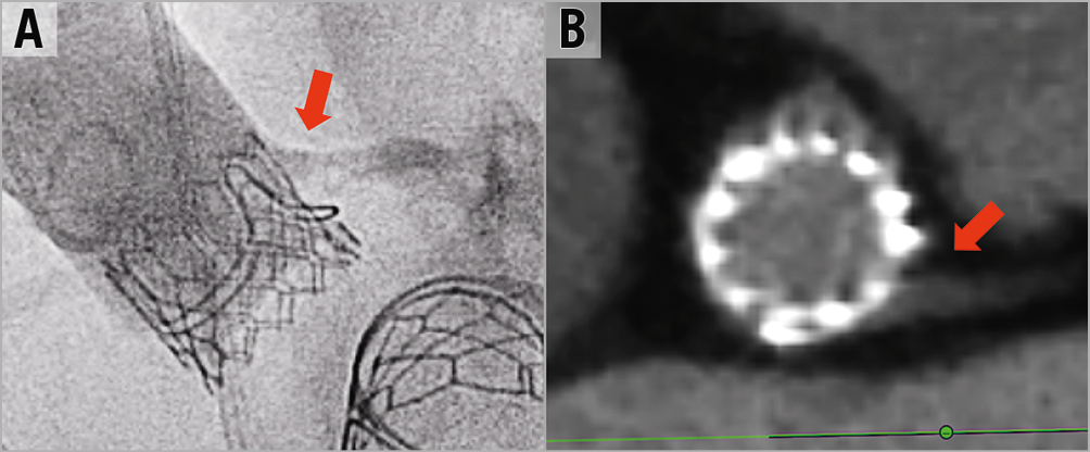
Figure 18. Post BASILICA and TAVR coronary assessment. A) & B) Post aortogram and CT assessment after BASILICA showing the proximity of the THV frame to the coronary ostium but with good contrast flow without leaflet content inside the coronary.
Conclusion
TAVR is increasingly performed in younger and lower-risk patient populations. Coronary obstruction is a life-threatening complication that must be prevented. Clinical experience suggests that BASILICA is an effective method to reduce the risk of coronary obstruction. The technique includes several steps that can be challenging without proper guidance. Assistance by operators who have already performed BASILICA seems to be crucial, and formal proctorship during initial procedures can ensure good clinical outcomes.
Conflict of interest statement
D. Dvir is a consultant to Edwards Lifesciences, Medtronic, Gore, Jena, and Abbott. The other authors have no conflicts of interest to declare.
Supplementary data
Moving image 1. Cine images of left BASILICA in the native aortic valve, followed by a balloon-expandable THV implantation.
Supplementary data
To read the full content of this article, please download the PDF.
Moving image 1. Cine images of left BASILICA in the native aortic valve, followed by a balloon-expandable THV implantation.