Abstract
Aims: While bioresorbable vascular scaffolds (BVS) are increasingly used in clinical practice, their behaviour when post-dilated beyond their recommended maximum overexpansion diameter remains sparsely documented. We aimed to test the overexpansion of the BVS scaffold in vitro and evaluate the impact of excessive scaffold oversizing on focal point support.
Methods and results: We examined the post-expansion behaviour of the bioresorbable vascular scaffold (3.0 mm and 3.5 mm Absorb BVS; Abbott Vascular, Santa Clara, CA, USA) after overexpansion with non-compliant (NC) balloons of increasing diameters. After each oversizing step, the scaffolds were measured and inspected for strut disruption using microscope and optical coherence tomography imaging. Point force mechanical measurements on single scaffold struts were also performed to evaluate the impact of excessive scaffold overstretching on focal mechanical support. 3.0 mm and 3.5 mm scaffold sizes could be post-expanded up to 1 mm above their nominal diameters without any strut fracture when deployed without an external constraining model. Importantly, when overexpansion of both scaffold sizes was repeated using a constraining silicone lesion model, only post-expansion with an NC balloon size 0.5 mm larger than the scaffold nominal sizes could be performed without strut fractures. Point force compression analysis on single struts shows that overstretched struts with fractures provided lower focal strength compared to overexpanded ring segments without fractures and normal segments expanded at nominal pressure.
Conclusions: In our experiments, only overexpansion with an NC balloon 0.5 mm larger than the BVS size was feasible for BVS deployed inside an arterial lesion model. Overexpansion of the BVS scaffold beyond recommended post-dilation limits can lead to strut disconnections and focal loss of mechanical support.
Introduction
Bioresorbable scaffold (BRS) technology is promising for changing the landscape of percutaneous coronary intervention (PCI) by treating diseases and restoring vessel function without the long-term limitations of conventional metallic stents1-3.
The Absorb everolimus-eluting bioresorbable vascular scaffold (Absorb BVS; Abbott Vascular, Santa Clara, CA, USA) was the first fully biodegradable polymer scaffold to become commercially available (CE mark) for the treatment of coronary diseases, and its use in clinical practice has been rapidly expanding since.
Recently, several reports have warned about the risk of incomplete scaffold apposition in BVS4-8. Restriction on post-dilatation to 0.5 mm above scaffold size has, however, been seen as an important limiting factor, particularly in long lesion and bifurcation treatment where diameters across the lesion may exceed the post-expansion limit of the scaffold4,9-12.
BVS are increasingly used for the treatment of complex coronary lesions6,7,13. Recently, several in vitro studies investigated the behaviour of BVS scaffolds in bifurcation, showing the applicability of side branch post-dilatation and the low-pressure kissing balloon technique12,14. Nevertheless, contrary to metallic stents, expansion of polymer struts close to their geometrical limit can lead to acute strut disruption, and strut rupture detectable by OCT has also been shown in vivo after overstretching of a BRS4. Overexpansion of BVS with larger post-dilatation diameter balloons and the consequence of strut disruption on local mechanical support still remain sparsely documented.
Methods
OVEREXPANSION TESTING
We examined in vitro the post-expansion behaviour of the Absorb BVS after post-expansion with non-compliant (NC) balloons of increasing sizes. All experiments were performed in a water bath at 37°C.
Absorb BVS samples, 3.0 and 3.5 mm, were deployed in vitro at their nominal pressure (7 atm) using slow inflation steps (1 atm/2 sec). After measurements were performed on each sample at its nominal deployment size, post-dilatation of the proximal part of the scaffolds was performed with a 4.0×12 mm NC balloon inflated to 14 atm (expected diameter, 4.09 mm), followed by a 4.5×15mm NC post-dilatation balloon inflated to 14 atm (expected diameter, 4.53 mm) (NC Quantum Apex; Boston Scientific, Marlborough, MA, USA). The 3.5 mm scaffolds were additionally post-dilated with a 5.0×12 mm NC balloon at 14 atm (expected diameter, 5.02 mm) (NC Quantum Apex) (Figure 1, Figure 2).
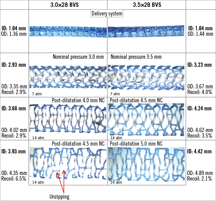
Figure 1. Nominal pressure expansion and post-dilatation of 3.0 and 3.5 mm BVS scaffolds with increasing balloon sizes. Post-dilatation was performed with non-compliant (NC) balloons 1 mm and up to 1.5 mm above the scaffold sizes. Microscope measurements of the scaffold diameter and images of the scaffolds were taken at each step. Results analysed under the microscope indicate that post-dilatation beyond 1 mm above the size of the scaffold can produce strut rupture and the “unzipping” phenomenon. ID: inner diameter; OD: outer diameter
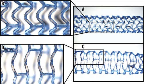
Figure 2. Changes in microscopic appearance during BVS overexpansion. A) 3.0 mm BVS scaffold deployed at nominal pressure. C) Segment overexpanded with a 4.0 NC balloon. Close-ups (B & D) reveal the straightening of the scaffold strut with the strut hinge dimmed on microscope image (creasing).
OVEREXPANSION IN A CONSTRAINING SILICONE LESION MODEL
Overexpansion of the 3.0 mm BVS scaffold was repeated inside a constraining lesion model made from silicone (MED-4735 with 35 Shore hardness; NuSil, Lake Mary, FL, USA) with a 0.45 mm wall thickness, a reference diameter of 2.75 mm and representative of a 40% diameter stenosis. We deployed 3.0 mm scaffolds within a silicone lesion model at nominal pressure (7 atm, inflation at 1 atm/2 sec). The scaffolds were then post-dilated using their delivery balloons to 18 atm (expected diameter, 3.5 mm). Finally, the scaffolds were post-dilated either with a 3.5×10 mm NC balloon at high pressure 30 atm (expected diameter, 3.85 mm), or using a 4.0×12 mm diameter NC balloon 14 atm (expected diameter, 4.09 mm). We additionally tested overexpansion of a 3.5 mm size scaffold within the same silicone lesion model. The scaffold was post-dilated with a 4.0×12 mm and a 4.5×15 mm NC balloon at 14 atm (expected diameter, 4.53 mm).
MICROSCOPE AND OCT ASSESSMENT
At each step, the scaffolds were imaged and their diameters measured using a stereomicroscope (Leica MZ16FA Fluorescence Stereomicroscope; Leica Microsystems, Wetzlar, Germany), both at inflation and after deflation of the balloon. During oversizing, the scaffolds were inspected for strut disruption, and the inflation pressure at which strut disruption started to occur was recorded. Final results were also imaged by intravascular optical coherence tomography (OCT) imaging (C7 with a Dragonfly™ OCT catheter; St. Jude Medical, St. Paul, MN, USA).
For each of the overexpansion experiments and fracture assessment, three different samples were used.
Microscopic measurements were performed with an estimated approximation of 0.05 mm. The results of the experiments are provided as mean with standard deviation (±SD) between different samples. We performed different expansion and post-dilatation experiments (21 post-expansion microscopy and OCT measurements in the water experiments and 13 post-expansion in the lesion model). A total of 34 different expansions on 10 samples were performed for the study. Comparisons between measurements were tested by analysis of variance (ANOVA) with a multiple comparisons post hoc test (GraphPad Prism, La Jolla, CA, USA).
POINT FORCE MECHANICAL MEASUREMENT
Samples of both BVS sizes (3.0 mm and 3.5 mm) with proximal overexpansion at the largest post-dilatation sizes (4.5 mm and 5.0 mm, respectively) were subjected to single strut point force compressive tests (Instron 5566 Universal Testing Machine; DatapointLabs, Ithaca, NY, USA) (Figure 3A). Two samples of each scaffold size were used to test point strut mechanical properties. Different strut locations for each scaffold were subjected to a compressive point force on the strut covering a reduction of 1.5 mm in diameter. Three different categories (strut locations) were compared: 1) post-dilated strut near fracture site; 2) post-dilated strut with no fracture; and 3) non-post-dilated strut at nominal diameter with no fracture (Figure 3B). Experiments were repeated on a minimum of three different struts, and data acquired on the Instron machine were analysed by plotting the compressive load corresponding to up to 1.5 mm compression. The highest force observed within the curve up to 1.5 mm compression is recorded as the maximum compressive force. The maximum force after the inflection point was computed by taking the intersection between the load/extension curve and a line parallel to the linear portion of the load/extension curve offset by 0.1 mm. The stiffness was computed by taking the gradient of the linear portion of the curve. Point force measurements performed on the expanded scaffolds (maximum force and stiffness) are provided as averages on a minimum of three different strut compression experiments. All point force results are displayed as mean±SD. Comparisons between the results of the different strut locations were tested by ANOVA and Tukey’s multiple comparison test.
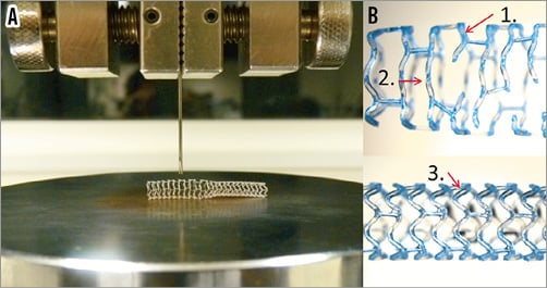
Figure 3. Instron single strut point force testing. A) A modified needle was clamped on the Instron Universal Testing Machine to enable it to contact and apply load on a single strut. The scaffold is laid on the platform along its length so that the needle measures the resistance and radial support transmitted through the strut. The force required to compress the strut by 1.5 mm was recorded. B) Categories tested included: 1) post-dilated strut next to fracture site, 2) post-dilated strut with no fracture, and 3) non-post-dilated strut at nominal diameter.
Results
BVS OVEREXPANSION TO TENSILE LIMIT
Table 1 and Figure 4 summarise the results and lumen diameters obtained at each post-dilatation step carried out on the 3.0 mm and 3.5 mm Absorb BVS.
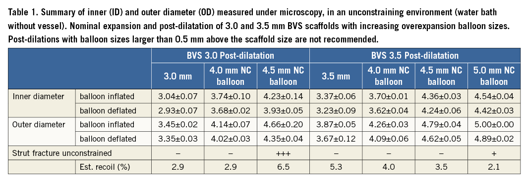
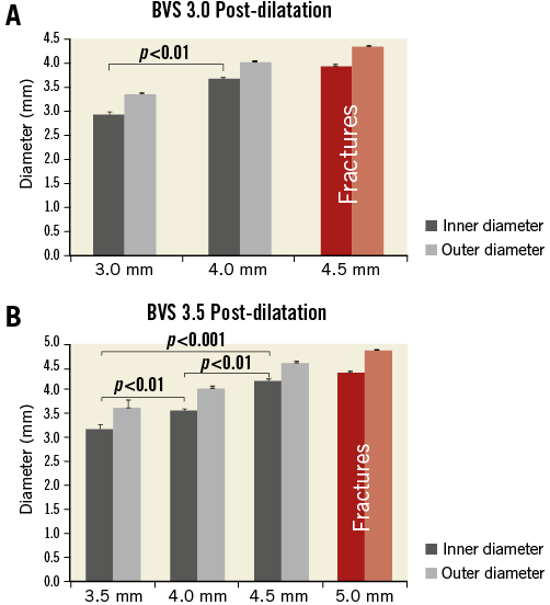
Figure 4. BVS overexpansion without constraining models: inner diameter (ID) and outer diameter (OD) measured directly under the microscope (Table 1). A) Nominal expansion and overexpansion of 3.0 BVS scaffolds with 4.0 mm and 4.5 mm post-dilatation NC balloons (inflated at 14 atm). B) Nominal expansion and overexpansion of 3.5 BVS scaffolds with 4.0 mm, 4.5 mm and 5.0 mm post-dilatation NC balloons (inflated at 14 atm). Without a constraining model, no strut ruptures were observed with an NC post-dilatation balloon up to 1.0 mm above the scaffold size (up to 14 atm). However, ruptures of the strut were observed in all experiments when the post-dilatation balloon size was larger than 1 mm above the nominal diameter.
Both 3.0 mm and 3.5 mm scaffold sizes could be overstretched with an NC balloon up to 1 mm above the scaffold nominal diameter.
The achieved lumen diameter (considering the minimal inner scaffold diameter) was on average 3.68±0.06 mm after overexpansion of the 3.0 mm scaffold with a 4.0 mm NC balloon at 14 atm (achieved overexpansion, 36%). For the 3.5 mm scaffold, the achieved minimal lumen diameter was on average 4.24±0.06 mm after overexpansion with a 4.5 mm NC balloon at 14 atm.
The minimal inner scaffold diameters measured from both sizes before fracture were found to be approximately 0.7 mm above the scaffold size.
Overexpansion with balloon sizes larger than 1 mm above the scaffold nominal diameter resulted in the disruption of struts: 3.0 mm scaffolds oversized with a 4.5 mm NC balloon resulted in extensive strut fracture sites (on average 12.7±3.9 fractures) as compared to 3.5 mm scaffolds oversized with a 5.0 mm NC balloon (1.3±1.2 fractures).
Because the overexpansion was unconstrained, the minimal inner lumen diameter after post-dilatation was maintained at 3.93±0.05 mm on average after overexpansion of the 3.0 mm scaffold with a 4.5 mm NC balloon at 14 atm despite multiple serial fractures. For the 3.5 mm size, the measured minimal lumen diameter was on average 4.42±0.03 mm after overexpansion with a 5.0 mm NC balloon at 14 atm.
ID and OD microscope measurements showed satisfactory repeatability with an average error between repeated measures of 0.04 mm. Standard deviation between results from different experiments was on average 0.06 mm, showing good inter-experiment reproducibility.
STRUT DEFORMATIONS
An increase in overexpansion with a larger post-dilatation diameter caused the scaffold struts to straighten with strain visible under the microscope at the strut joints (Figure 1, Figure 2). At the point where fractures start to appear (tensile limit), the scaffold rings were already extensively stretched (circular appearance).
Interestingly, 2D and 3D OCT assessment following overexpansion of the BVS scaffolds revealed that strut disconnections were not systematically appreciable from only 2D cross-sectional OCT (Figure 5). In cases of mild fracture or few strut disconnections (Figure 5A, Figure 5B, Moving image 1), the fractured struts were only apparent from the 3D reconstructions, whereas 2D OCT cross-sections showed a circular scaffold contour without any indication of strut disconnection (Figure 5C, Figure 5D). On the contrary, in more severe fracture cases with multiple sites of strut disconnection along the scaffold (Figure 5E, Figure 5F, Moving image 2), 2D OCT cross-sections were suggestive of the strut fractures (Figure 5G: overlapping struts, Figure 5H: sharp change in scaffold circumference).
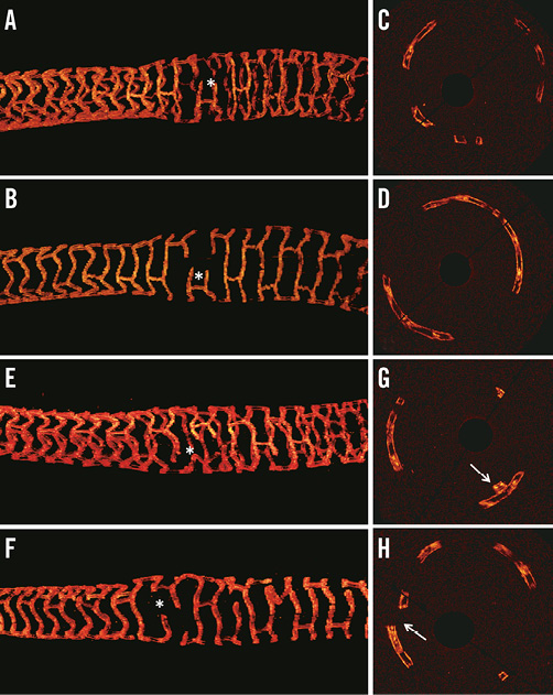
Figure 5. OCT assessment of strut deformation following partial overexpansion of the BVS scaffolds. A) & B) Overexpansion of a 3.5 mm scaffold with a 5.0 NC balloon. Corresponding OCT cross-sections (C & D) show a circular distribution of the strut with no clear indication of the presence of strut fracture. Strut disconnections are only visible on the 3D OCT view (* in A & B and Moving image 1). E) & F) Another example with overexpansion of a 3.0 mm scaffold with a 4.5 NC balloon which resulted in some scaffold fractures (* and Moving image 2). For more severe cases of scaffold fracture, 2D OCT cross-sections (G & H) are indicative of the presence of strut fracture (G: overlapping struts, H: sharp change in scaffold circumference) .
OVEREXPANSION BEHAVIOUR IN THE PRESENCE OF A CONSTRAINING LESION
When overexpansion of a series of 3.0 mm scaffolds was repeated using a constraining silicone lesion model, 3.5 mm post-expansion, even with a high-pressure (30 atm) 3.5 NC balloon, could be performed without causing fractures. However, post-dilatation with a 4.0 mm NC balloon caused multiple strut fractures (on average 9.7±5.1), contrary to post-dilatation results without a constraining model (Figure 6, Table 2). Additionally, when a 3.5 mm size scaffold was deployed in the constraining silicone lesion model, post-expansion with a 4.0 mm NC balloon could be performed without fractures. However, post-dilatation with a 4.5 mm NC balloon caused multiple strut disruptions (n=11 disruptions) (Table 2).
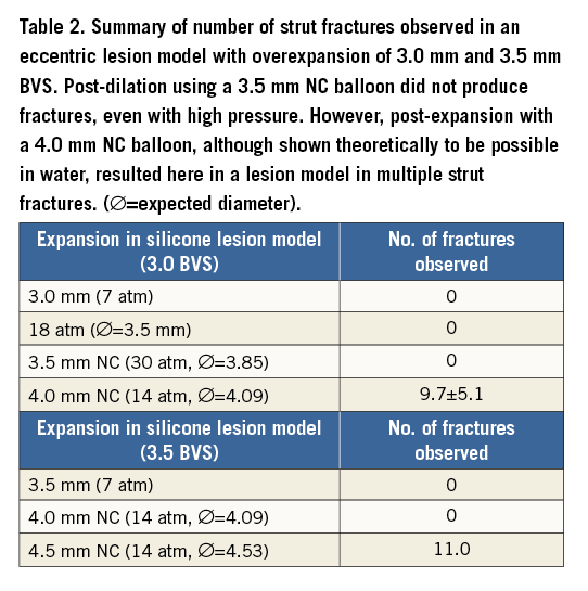

Figure 6. Microscope images of 3.0 mm BVS scaffolds deployed within an in vitro silicone lesion model and overexpanded with 3.5 mm and 4.0 mm diameter NC balloons. Left panel: 3.0 mm BVS scaffold deployed and post-expanded to 3.5 mm diameter: A) balloon inflated; B) balloon deflated, no fracture present. Right panel: 3.0 mm BVS scaffold post-expanded to 4.0 mm diameter: C) balloon inflated; D) balloon deflated. Note the fractures observed in (D) (circled in yellow).
MECHANICAL POINT FORCE MEASUREMENTS
The point force single strut compression analysis shows that post-dilated struts with fractures have lower local focal strength than post-dilated rings with no fractures or normal non-post-dilated segments (expanded at nominal pressure). Maximum point force measured for fractured, no fracture and normal ring were, respectively: 0.17, 0.29 and 0.44 N for BVS 3.0 (p<0.01); and 0.19, 0.30 and 0.33 N for BVS 3.5 size (p<0.01) (Figure 3, Figure 7, Figure 8).
Additionally, for both sizes, we also measured the impact of a fracture when load was applied within the same post-dilated ring at a point located directly opposite the fracture site. The point force opposite the fracture site was lower compared to non-fractured overstretched struts in the BVS 3.5 samples (maximum force: 0.23±0.00 vs. 0.30±0.03, ns; results not displayed) but similar in the BVS 3.0 samples (maximum force: 0.29±0.01 vs. 0.29±0.02, ns; results not displayed).
The results also indicate that extremely large post-expansion may have an undesirable effect on the mechanical properties of the scaffold. Overstretched struts without fracture showed on average comparable maximal point force results to the nominal size struts on the 3.5 mm size scaffolds (0.30±0.02 vs. 0.33±0.04 N); compressive force was, however, lower on the overstretched 3.0 mm scaffold segment compared to the strut deployed at nominal size (0.29±0.01 and 0.44±0.04 N, p<0.01) (Figure 7, Figure 8).
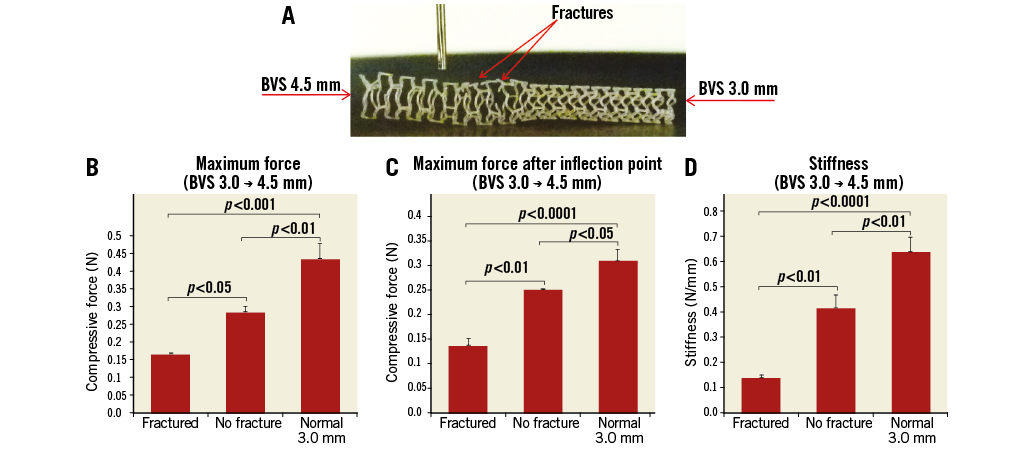
Figure 7. Impact of oversizing on focal mechanical support. A) 3.0 BVS after proximal overexpansion using a 4.5 NC balloon. B) Maximum point force. C) Maximum force after inflection point. D) Stiffness measured for the different sites compared: 1) oversized strut near fracture site (Fractured), 2) oversized strut with no fracture (No fracture), and 3) non-oversized strut at nominal diameter with no fracture (Normal).
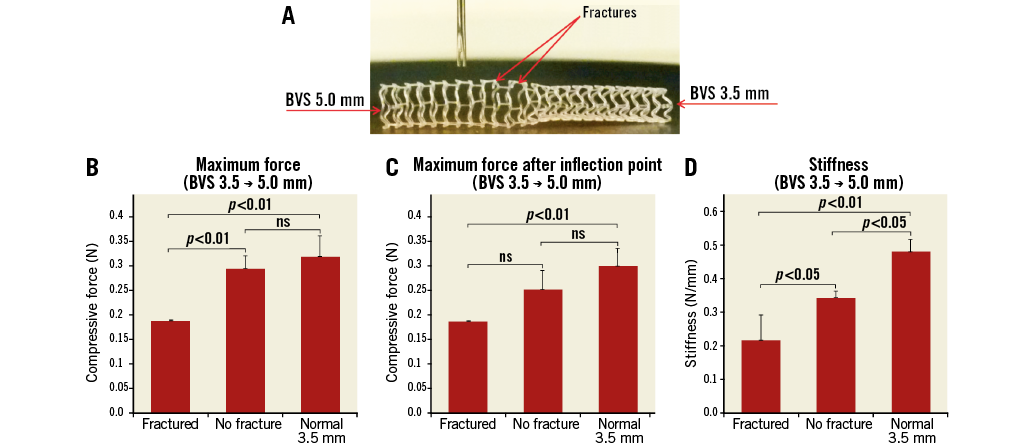
Figure 8. Impact of oversizing on focal mechanical support (3.5 size). A) 3.5 BVS after proximal overexpansion using a 5.0 NC balloon. B) Maximum point force. C) Maximum force after inflection point. D) Stiffness measured for the different sites compared: 1) oversized strut near fracture site (Fractured), 2) oversized strut with no fracture (No fracture), and 3) non-oversized strut at nominal diameter with no fracture (Normal).
Discussion
The main insights from this in vitro BVS post-expansion study are that:
– Overexpansion behaviour with BVS depends on scaffold size (3.0 mm and 3.5 mm sizes). When oversized with NC balloons above their nominal size in a non-constrictive in vitro environment, 3.5 mm scaffold overexpansion resulted in less overstretching and less strut disconnection compared to the 3.0 mm scaffold size.
– When overexpansion was repeated in silicone lesion models, only post-expansion with an NC balloon 0.5 mm above the scaffold size could be performed without causing fractures. Post-dilatation with an NC balloon 1 mm larger than the scaffold sizes caused multiple strut fractures for both scaffold sizes.
– OCT analysis after oversizing of the BVS scaffolds revealed that individual strut discontinuities are not always detectable based on cross-sectional 2D OCT.
– Based on point force mechanical measurements on a single strut, our results suggest that fractures on a scaffold ring can result in a local loss of mechanical support, particularly in cases of severe serial disruptions with multiple strut disconnection sites along the length of the scaffold.
Relevance and implications of the study
Metallic stents are generally considered to have wider post-expansion allowance and theoretical overexpansion capacity as compared with BRS scaffolds. Several previous in vitro studies have investigated stent oversizing and the impact of post-dilatation on metallic drug-eluting stents15-20. In a previous in vitro study, we tested the post-expansion response of DES with a post-dilatation balloon up to 6 mm diameter19. It should be noted that, although metallic stents have larger theoretical expansion limits, overstretching can also decrease their resistance to fatigue (with the risk of late fracture), and therefore the recommended post-dilatation limit provided by manufacturers for metal DES is generally 0.5-0.75 mm above the stent nominal size19.
Data on BVS behaviour with overexpansion are currently limited. The manufacturer’s current recommendation is to avoid expansion of the scaffold to diameters larger than 0.5 mm above their nominal size. In vitro experimentation of BVS behaviour in the particular setting of bifurcation has been previously reported by Dzavik and others12,14, showing i) the feasibility of SB ostium optimisation through the scaffold strut, and ii) risk of strut rupture with a high-pressure kissing balloon technique. However, to our knowledge, the impact of overexpansion beyond the recommended post-dilation limit and its impact on the local scaffold support have not yet been described.
Information about the consequence of BVS overexpansion in terms of risk of fractures and loss of radial support is sparse. Insights on scaffold behaviour beyond the recommended post-dilatation diameter are important for understanding the limitation of each device and the potential risks associated with overexpansion beyond recommendations.
BVS overexpansion: insights from unconstrained deployments
We identified two separate overexpansion scenarios from our in vitro experiments outside the lesion model. 1) For post-expansion up to 1.0 mm above the scaffold size, we observed overexpansion and straightening of the scaffold rings without fractures. 2) Beyond 1.0 mm (post-expansion with an NC balloon 1.5 mm above the scaffold size), we observed some fractures in both scaffold sizes, manifesting even at low pressure (9 atm).
Fewer strut fractures were observed in the 3.5 mm scaffolds (on average 1.3±1.2 fractures) with only a relatively limited impact on the scaffold focal mechanical support (Figure 7). In comparison, extensive scaffold overstretching in the 3.0 mm scaffold resulted in more strut disconnections (on average 12.7±3.9) and larger focal drop in mechanical scaffolding. Multiple strut fractures could readily occur at once (strut unzipping) during inflation with an oversized NC balloon larger than 1 mm above the scaffold size. Such serial scaffold strut fractures were observed on the 3.0 mm BVS size post-expanded with a 4.5 NC balloon, with the first fracture occurring at 9 atm.
Insights from constrained deployments
An important insight from the in vitro experiments is that BVS overexpansion behaviour tested without a constraining lesion model produced different results from the experiment in a model with the presence of a lesion. When overexpansion of the 3.0 mm scaffolds was repeated in a constraining silicone lesion model, only 3.5 mm NC post-expansion could be performed without incurring fractures. Post-dilatation with a 4.0 mm NC balloon caused multiple strut disconnections.
We see here that experiments performed in a water bath without a lesion constraining the scaffold may overestimate the overexpansion limit of the scaffolds. Such simple conditions may not be representative of the in vivo behaviour in the presence of a constraining vessel with fibro-calcified lesions which are likely to accentuate stress points on the scaffold struts if overexpansion beyond 0.5 mm is performed.
In practice, the protocol for BVS implantation differs significantly from that of a conventional metallic stent. Current recommendations to achieve effective scaffold deployment include ensuring optimal predilatation of the lesion before advancing the scaffold; slow expansion during deployment (2 atm every five seconds); and post-dilatation, albeit within the limit, to a maximal diameter of ≤0.5 mm larger than the nominal scaffold size.
Vessel preparation before BVS deployment is essential for correct scaffold expansion and optimal apposition of the scaffold without overstretch13,21-23. OCT-guided BVS implantation with a 1:1 balloon:vessel predilatation was recently shown to result in an improvement in scaffold expansion21.
Stents are frequently achieving lower MLD in vivo than predicted by compliance charts24-26. Because of the known limitation on post-expansion capacity with BVS, incomplete scaffold apposition must be absolutely prevented by predilatation and correct sizing of the scaffold with quantitative angiography (QCA) or intravascular imaging. Insights from this study and other in vitro studies are important for BRS sizing (choice between 3.0 mm and 3.5 mm size) and guidance on post-dilatation balloon sizing.
Effects of strut disconnection
Results analysed via microscopy indicate that post-dilatation 1 mm above the size of the scaffold can produce overstretch with the “unzipping” phenomenon (multiple strut rupture at once). We see from the mechanical point force results that an isolated ring fracture only affects scaffold point support locally at the fracture site. On the other hand, multiple serial strut ruptures affect the overall scaffold radial support (hoop support). Such serial fractures are more likely to affect overall scaffold mechanical support and lead to vessel recoil or local plaque prolapse.
Serial ruptures caused by acute overstretching of a scaffold have been previously reported in vivo. In an early case of BVS implantation in vivo, significant disruption of a BVS 3.0 mm scaffold was observed in a patient after post-dilatation with a 3.5 compliant balloon at 16 atm (expected diameter, 4.0 mm)4. Cases of strut discontinuity have been reported by OCT, including OCT assessments performed in the ABSORB trial series27-30. The presence of strut discontinuities has been reported in OCT both during implantation, often after extreme overstretching4,13, and at follow-up, including cases where no signs of strut rupture were evident during implantation29,30. Scaffold dismantling is part of the natural healing and absorption processes of the scaffold; there is currently no evidence that early scaffold disruption may be associated with worse outcomes.
Importance of optimisation to minimise malapposition: OCT insights
On the other hand, incomplete stent expansion assessed with intravascular imaging is generally considered a predictor of stent thrombosis and adverse outcomes31-35. The importance of post-dilatation in achieving better stent expansion is well known in metallic stents36-38. Final minimal lumen area has been shown to be a strong predictor of both restenosis and stent thrombosis in metallic stents39,40. Post-dilatation of BVS has therefore generally also been encouraged within recommended limits to avoid incomplete apposition and improve BVS strut embedding leading to a reduced risk of scaffold thrombosis10,11.
In a serial analysis of malapposed struts of BVS scaffold using OCT, Gomez Lara showed that the lack of BVS strut apposition at baseline was related to the presence of uncovered struts and intraluminal masses at six-month follow-up. Late acquired ISA was associated with scaffold pattern irregularities, which were assumed to be related to overstretching of the scaffold. Malapposition of rings at the ostium of a tapering vessel is common but should be corrected only within the appropriate expansion range of the scaffold to avoid overstretching and fracture41.
Despite the limits on overexpansion diameter, the optimisation of the BVS is important, possibly even more than in metal stents because of the larger strut thickness23. Scaffold thrombosis is still a new phenomenon and remains a matter of debate7,8,23,42. Recently, reports of clinical outcomes with BVS in broader, more complex “real-world” patient populations are emerging6,7,13. Interestingly, in these real-world experiences, the studies with the lowest BVS thrombosis rates (Costopoulos et al and Mattesini et al, both with 0% ST) were also those with the highest post-dilatation rates (99.3% and 100%) and the highest post-dilatation pressures (>0 atm in both studies)13,43. Also of note, both studies reported the highest lesion complexity (type B2-C lesions were 83.9% and 100%, respectively) and intracoronary imaging guidance was almost systematically used13,43. Although these studies were not sized to provide definitive answers, their results underline that lesion preparation, accurate scaffold sizing, post-deployment optimisation and possibly intracoronary imaging guidance are particularly important steps for BVS implantation.
Study limitations
Results presented in this paper must be carefully interpreted, as in vitro deployment can only provide an approximation of the real in vivo scaffold expansion behaviour in a diseased arterial vessel.
Aging has been reported to impact on scaffold properties. We used recently expired scaffolds for the in vitro experiments and we could not assess the aging effect on the results.
We did not investigate the effect of the kissing balloon technique and overlapping scaffold struts in this study. Analysis of the impact of the kissing balloon technique on scaffold geometry has been covered in previous studies12,14.
The force exerted on the scaffold during expansion in a tortuous diseased artery vessel is expected to be significantly larger in vivo than in a simple in vitro model, particularly in the presence of calcified/stiff fibroatheromatous plaque. The impact of different plaque composition was not evaluated in this study.
Conclusion
In our experiments, only overexpansion with a 0.5 mm NC balloon was feasible for BVS deployed inside arterial lesion models. Overexpansion of the BVS scaffold beyond its recommended post-dilatation limit can lead to strut disconnections and a local reduction in mechanical support, and should therefore be avoided.
Sizing and post-expansion of BVS with an NC balloon should take into account the compliance chart of the balloon to avoid stretching of the scaffold above the recommended post-expansion diameter.
| Impact on daily practice Bioresorbable scaffolds (BRS) are increasingly used in clinical practice, including for treatment of complex lesions such as bifurcations. Currently post-expansion of BRS is encouraged to optimise strut apposition within a maximal limit of 0.5 mm above the scaffold size. Behaviour beyond the recommended maximum expansion diameter still remains sparsely documented. We tested BVS oversizing in different in vitro environments with the aim of exploring when overexpansion starts to affect BVS strut integrity and local mechanical support. Excessive overexpansion of the BVS scaffold beyond post-dilation limits should be considered carefully as it may lead to strut disconnections and a focal loss of mechanical support. |
Acknowledgement
The authors would like to thank Dr R. Rapoza for his review of the manuscript.
Conflict of interest statement
This in vitro study was initiated and conducted independently by the authors. H. Nef received speaker’s honoraria and institutional grants from Abbott Vascular. The other authors have no conflicts of interest to declare.
Supplementary data
Moving image 1. OCT after overexpansion of a 3.5 mm BVS scaffold with a 5.0 NC balloon.
Moving image 2. OCT after overexpansion of a 3.0 mm BVS scaffold with a 4.5 NC balloon.