Abstract
Background: Bioprosthetic valve fracture (BVF) can be used to improve transcatheter heart valve (THV) haemodynamics following a valve-in-valve (ViV) intervention. However, whether BVF should be performed before or after THV deployment and the implications on durability are unknown.
Aims: We sought to assess the impact of BVF timing on long-term THV durability.
Methods: The impact of BVF timing was assessed using small ACURATE neo (ACn) or 23 mm SAPIEN 3 (S3) THV deployed in 21 mm Mitroflow valves compared to no-BVF controls. Valves underwent accelerated wear testing up to 200 million (M) cycles (equivalent to 5 years). At 200M cycles, THV were evaluated by hydrodynamic testing, second-harmonic generation (SHG) microscopy, scanning electron microscopy (SEM) and histology.
Results: At 200M cycles, the regurgitant fraction (RF) and effective orifice area (EOA) for the ACn were 8.03±0.30%/1.74±0.01 cm2 (no BVF), 12.48±0.70%/1.97±0.02 cm2 (BVF before ViV) and 9.29±0.38%/2.21±0.0 cm2 (BVF after ViV), respectively. For the S3 these values were 2.63±0.51%/1.26±0.01 cm2, 2.03±0.42%/1.65±0.01 cm2, and 1.62±0.38%/2.22±0.01 cm2, respectively. Further, SHG and SEM revealed a higher degree of superficial leaflet damage when BVF was performed after ViV for the ACn and S3. However, the histological analysis revealed significantly less damage, as determined by matrix density analysis, through the entire leaflet thickness when BVF was performed after ViV with the S3 and a similar but non-significant trend with the ACn.
Conclusions: BVF performed after ViV appears to offer superior long-term EOA without increased RF. Ultrastructure leaflet analysis reveals that the timing of BVF can differentially impact leaflets, with more superficial damage but greater preservation of overall leaflet structure when BVF is performed after ViV.
Introduction
Indications for transcatheter aortic valve implantation (TAVI) have been rapidly expanding in the past decade. Among these, valve-in-valve (ViV) TAVI in patients with a failed surgical bioprosthesis is now an established treatment option123. However, patient-prosthesis mismatch and a suboptimal expansion of the transcatheter heart valve (THV) may lead to a high transvalvular gradient after ViV TAVI and potentially impact long-term outcomes, including impaired haemodynamic performance and durability3456. To overcome this issue, bioprosthetic valve fracture (BVF) has been introduced and has been shown to lower the transvalvular gradient which is then sustained to at least 1 year7891011. BVF can be performed either before or after ViV TAVI, where the first option may lead to haemodynamic instability until the THV is implanted and the second option may potentially lead to damage of the THV leaflets. Clinical and bench research have demonstrated that BVF performed after ViV TAVI is associated with better THV expansion and haemodynamic performance812. However, the long-term impact of BVF is unknown, especially regarding the potential structural damage to the leaflets of the THV. The present bench study reports the impact of BVF timing on valve durability to an equivalence of 5 years of follow-up using accelerated wear testing (AWT) and microscopic and histological analyses. It describes the long-term results of a previously published report looking at the immediate results of BVF according to timing8.
Methods
This work is a bench study in which no human or animal subjects were included and thus did not require ethical approval.
Valves tested
ViV intervention was tested with a 23 mm SAPIEN 3 (S3; Edwards Lifesciences), and a small ACURATE neo (ACn; Boston Scientific) THV in a 21 mm Mitroflow (Sorin Group) (with a true inner diameter of 17 mm) surgical bioprosthetic valve. One Mitroflow valve was utilised to assess each testing condition and each THV design. A total of 6 Mitroflow valves were utilised: ViV without BVF, ViV with BVF before THV implantation, and ViV with BVF after THV implantation for both the S3 and the ACn (Central illustration).
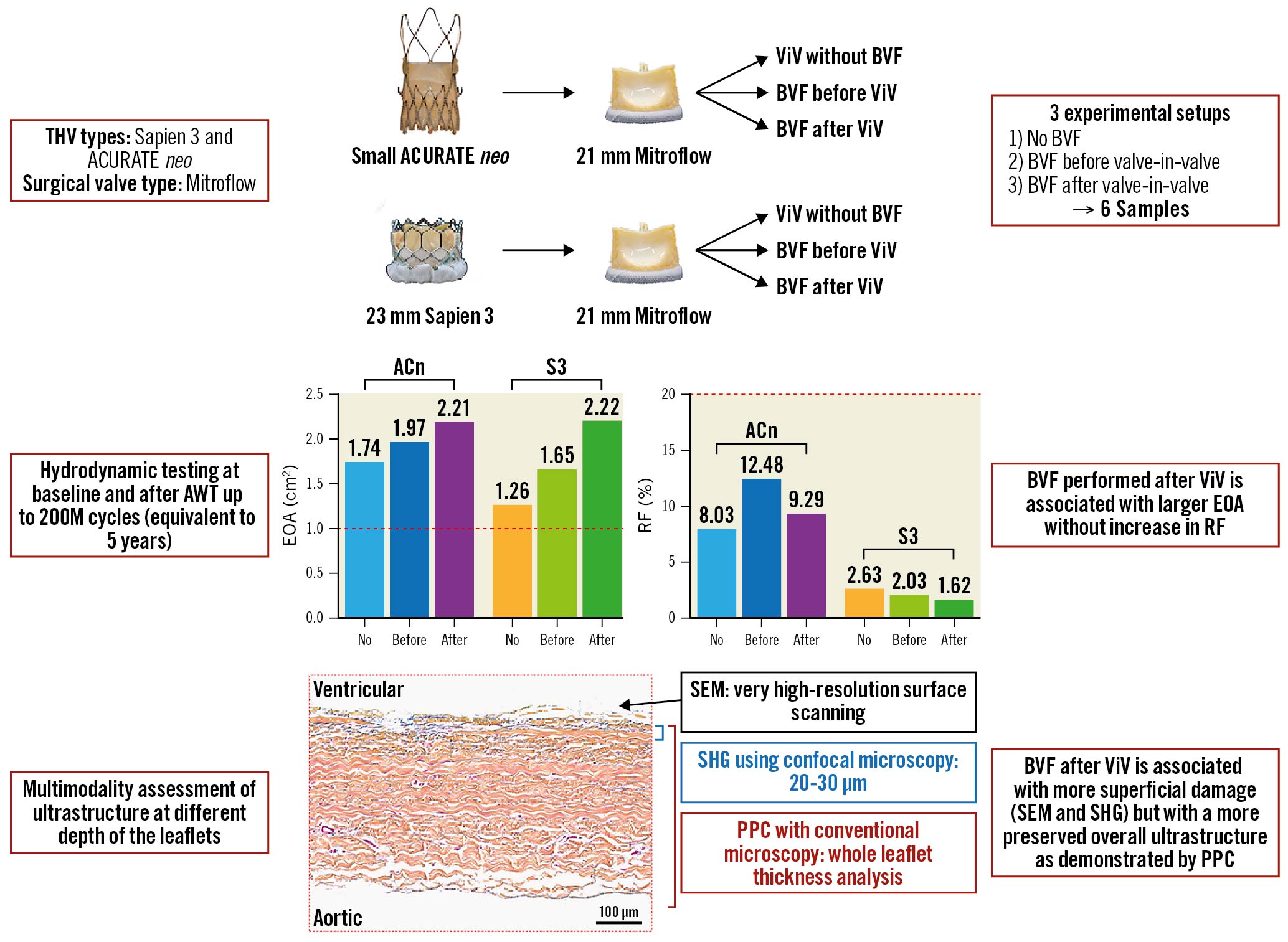
Central illustration. Study design and main findings. This study looked at 2 ViV combinations in 3 experimental setups (no BVF, BVF before ViV and BVF after ViV) and evaluated the impact of BVF timing on long-term valve hydrodynamic function as well leaflet integrity. BVF perfomed after ViV achieves the largest hydrodynamic benefit without long-term trade-offs in terms of THV performance or structural valve damage on bench analysis. ACn: ACURATE neo; AWT: accelerated wear testing; BVF: bioprosthetic valve fracture; EOA: effective orifice area; PPC: positive pixel count; RF: regurgitant fraction; S3: SAPIEN 3; SEM: scanning electron microscopy; SHG: second-harmonic generation; THV: transcatheter heart valve; ViV: valve-in-valve
Valve-in-valve bench procedure
The THV were positioned in the Mitroflow valves with the aim of achieving a “high” implant as previously reported1314. Ex vivo ViV using the S3 THV was performed with the centre marker of the S3 THV positioned just above the level of the sewing ring of the Mitroflow valve, and ex vivo ViV with the ACn THV was performed by positioning the upper crown just above the top of the stent frame.
Bioprosthetic valve fracture
BVF was performed using a 23 mm non-compliant TRUE DILATATION balloon valvuloplasty catheter (Bard Peripheral Vascular) as previously described15. Balloons were inflated using a set-up of a large syringe, an indeflator and a high-pressure stopcock. The balloon was filled by a hand injection of the syringe first and then the stopcock was opened to the indeflator to pressurise the balloon. The surgical valve was determined to have fractured when the inflation pressure quickly dropped in the absence of balloon failure.
Hydrodynamic assessment
Valve testing was performed in the ViVitro Labs testing facilities (ViVitro Labs, Canada). Hydrodynamic testing was performed using a commercially available pulse duplicator (ViVitro Labs), meeting the equipment requirements defined in ISO 5840-3 for pulsatile flow testing16 (Figure 1A). Hydrodynamic testing was performed at baseline and then every 50 million (M) cycles for the 6 THV up to 200M cycles. Valves were tested in accordance with ISO 5840-3:2013 and ISO 5840-1:2015 for 0M, 50M, 150M and 200M timepoints. By the 200M timepoint, the ISO 5840-3:2021 standard had been released, and testing was conducted according to the new standard1617. Surgical valves were sealed in a holder fabricated from silicone with a durometer of scale Shore A hardness of 40±5. Justification for the selection of the sample holder hardness was based on published data on acceptable tissue compliance181920. The test fluid used was a 0.9±0.2% sodium chloride test solution maintained at 37±2°C with 1 drop of preservative per 1L (Cosmocil; Lonza-Glenn). Valves were tested on the aortic side of the pulse duplicator with a spring-loaded disc valve (ViVitro Labs) on the mitral side of the pulse duplicator. Pulsatile forward flow performance was tested at a nominal beat rate of 70±1 beats per minute, a systolic duration of 35±5%, a mean aortic pressure of 100±2 mmHg, and simulated cardiac outputs of 5±0.1 litres per minute. The mean transvalvular gradient (mmHg), regurgitant fraction (RF, %) and effective orifice area (EOA, cm2) were assessed using ViviTest Software (ViVitro Labs).
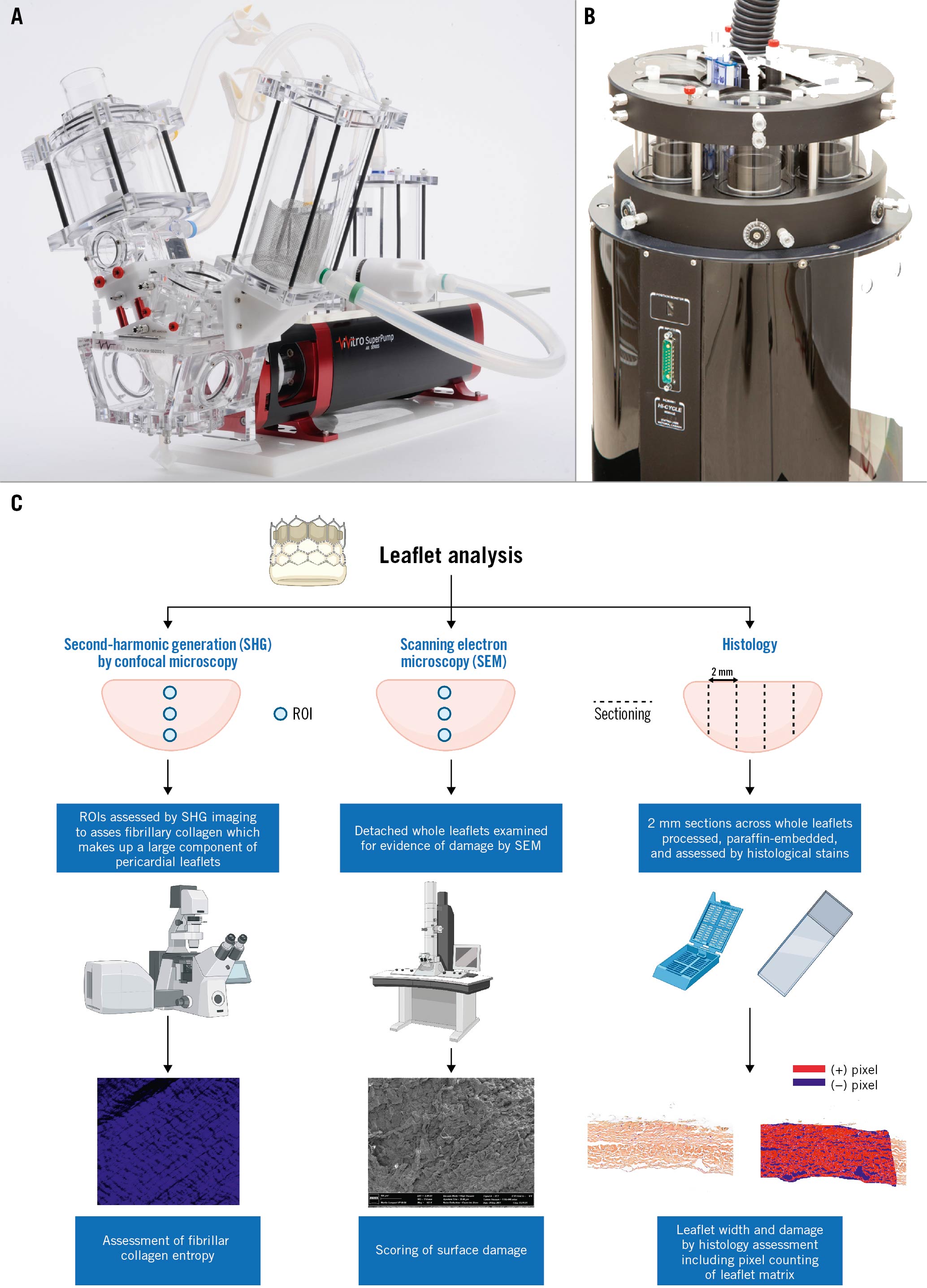
Figure 1. Experimental devices used for hydrodynamic testing and accelerated wear testing. A) Pulse duplicator used for the hydrodynamic testing. B) Accelerated wear tester for ViVitro Labs. C) Graphical illustration of the method used for leaflet analysis. Figure 1C was made with Biorender.com. ROI: region of interest
Accelerated wear testing
Valves were tested in accordance with ISO 5840-3:2015 using an accelerated wear tester (ViVitro HiCycle Durability Tester; ViVitro Labs) (Figure 1B). AWT was assessed to 200M cycles (equivalent to 5 years) as required by the ISO 5840-3:2021 guidelines.
Testing in an accelerated wear tester to 200M cycles took 6 months. Valve samples were mounted and tested in the accelerated wear tester at a cycle rate of 692 to 716 cycles per minute. The testing solution was composed of physiological saline at 37±2°C which was replaced every 50M cycles. Proper opening and closing were controlled daily using a stroboscope. A target differential pressure ≥100 mmHg was maintained for ≥5% of the duration of each cycle for at least 95% of the 200M cycles tested.
Evaluation of THV structural deterioration
Assessment of THV deterioration was determined based on serial hydrodynamic testing and visual inspection for leaflet damage. Hydrodynamic testing was used to assess the transvalvular gradient, RF and EOA. Serially measured RF were compared with minimum performance requirements in accordance with ISO 5840-3:2021 guidelines. The required transcatheter RF for acceptable performance as per the ISO 5840-3:2021 guidelines is ≤20%. The EOA varies by valve and was only considered for in-valve comparison every 50M cycles. All samples were visually inspected under magnification (8x) every 50M cycles to assess for mechanical leaflet damage. The presence of holes (perforation through all layers of the leaflet), tears (complete rip through all layers of the tissue), gross delamination (distinct separation of a layer of tissue from the surface), peeling (separation of layers where at least 1 edge can be moved away from the adjoining tissue or tissue layer creating a flap-like feature on the tissue surface), fracture, excessive deformation, or other mechanical breakdown and/or wear were recorded.
Valve gross imaging
Multimodality imaging with high-resolution photography and videos were performed at baseline and serially (every 50±2.5M cycles) during durability testing. Photographs of the inflow, outflow, and of each commissure of the THV were taken.
Histological examination
To assess for potential damages not seen on macroscopic examination, the THV leaflets were microscopically assessed (Figure 1C). To this end, the leaflets were removed from the device frame and cut into 2 to 4 mm sections that were subsequently embedded in paraffin. Movat’s pentachrome and haematoxylin and eosin staining were used to assess for collagen distribution and integrity. Image analysis was performed on high-resolution slide images generated using an Aperio slide scanner, using ImageScope software (Leica Biosystems). Histological analysis was completed on 2 (ACn) or 3 (S3) cross-sections of each analysed leaflet. One randomly selected leaflet was analysed per valve. The leaflet cross-section width was measured at 9 points distributed along the cross-section.
Analysis of the pericardial tissue composition to determine the percentage of area was completed using positive pixel counts (PPC; positive area) of selected regions of the included leaflets compared to the total cross-sectional area (positivity was defined by the number of positive pixels divided by the total number of pixels in the selected region of interest [ROI]) using ImageScope. For the S3, 2 ROI for both the aortic and ventricular aspects were selected per cross-section, ranging in size from 1.0 to 2.0×105 μm2, using a hue value of 0.01, a hue width of 0.98, and a colour saturation threshold of 0.04. For the ACn, the same methodology was applied but 3 ROI were used instead of 2 in order to compensate for the lower number of cross-sections on the ACn samples.
Second-harmonic generation microscopy imaging
Analysis of fibrillar collagen was completed with a second-harmonic generation (SHG) microscopy image analysis obtained from whole detached leaflets21. Briefly, leaflets were scanned using a Zeiss’ confocal microscope, using an 800 nm excitation laser and a 417 nm dichroic filter. The endogenous SHG signal was collected in the backward direction using the microscope’s internal detection system (multi-alkali photomultipliers, QUASAR detection system). SHG images were acquired at tissue depths of 20 and 30 μm within the pericardial leaflets. Imaging was repeated at 3 different ROI using the same parameters for each pericardial leaflet on both aortic and ventricular leaflet aspects (Figure 1C).
Texture analysis of SHG microscopy images
Entropy (arbitrary units) is a measure of the degree of disorder21 and was calculated for fibrillar collagen fibres at each ROI at 20 and 30 μm depths from the surface for each THV. Post-image processing was performed in ImageJ software (NIH). Briefly, using a custom-built texture analysis toolkit21, image background correction, intensity normalisation, calculation of the grey level co-occurrence matrix (GLCM), and image texture parameter (entropy) were carried out using Matlab 7.5 (MathWorks). The GLCM was calculated in 4 orientations: horizontal, vertical and the 2 diagonals (directions defined by 4 angles: 0°, 45°, 90° and 135°), and an average value was obtained. The GLCM represents the probability of the occurrence of a pixel pair with a given grey-tone difference, separated by a predefined distance, taken in a predefined direction. A computational window size of 8 pixels was adopted to extract features from 32-bit images.
Scanning electron microscopy
Scanning electron microscopy (SEM) was performed to assess for the presence of THV leaflet damage. SEM was performed as previously described21. Briefly, detached leaflets from each valve were imaged using a Quanta 3D FEG (field emission gun) microscope (FEI); areas of damage were noted, including fibre disarray and broken or fractured collagen fibres. A custom semiquantitative scale was used in order to grade the overall degree of damage on the surface of the leaflet. The scale is graded from 1 to 4 with the following corresponding degree of damage: score 1: no bundle detachment or fracture; score 2: collagen fibre fractures only; score 3: collagen bundle detachment only; score 4: collagen fibre fracture and bundle detachment (Figure 1C).
Statistical analysis
Hydrodynamic variables are reported as mean (averaged from 10 cycles) ±standard deviation. For leaflet thickness and positivity, values are reported per leaflet and represent the mean±standard error of the mean. Comparison of leaflet thickness and positive pixel count as well as entropy were measured using 1-way analysis of variance with Holm–Sidak’s correction for multiple comparisons. In all cases, statistical significance was taken as a p-value <0.05. Figures were realised with Prism version 9 (GraphPad).
Results
After accelerated wear testing to 200M cycles, equivalent to 5 years, the 3 experimental setups of BVF first, BVF after, and no-BVF, resulted in acceptable hydrodynamic performances for the ACn and the S3 according to ISO 5840-3:2015.
Regurgitant fraction
The evolution of the RF between baseline and 200M cycles is displayed in Figure 2. In this study, the surgical valves were sealed to the silicone holders. Therefore, the mechanism for RF in this study was not related to paravalvular leak. The mechanism for leak may be related to either an intervalvular (between the surgical valve and THV) leak or a central leak. After the initial drop in RF, the value generally remained stable throughout testing for both valve types, irrespective of BVF timing and with an RF <20% for all valves throughout 50-200M cycles. At the 200M cycle terminus of the experiment, the RF for the ACn was 8.03±0.30% (no BVF), 12.48±0.70% (BVF first) and 9.29±0.38% (BVF after ViV), and for the S3, these values were 2.63±0.51% (no BVF), 2.03±0.42% (BVF first) and 1.62±0.38% (BVF after ViV).
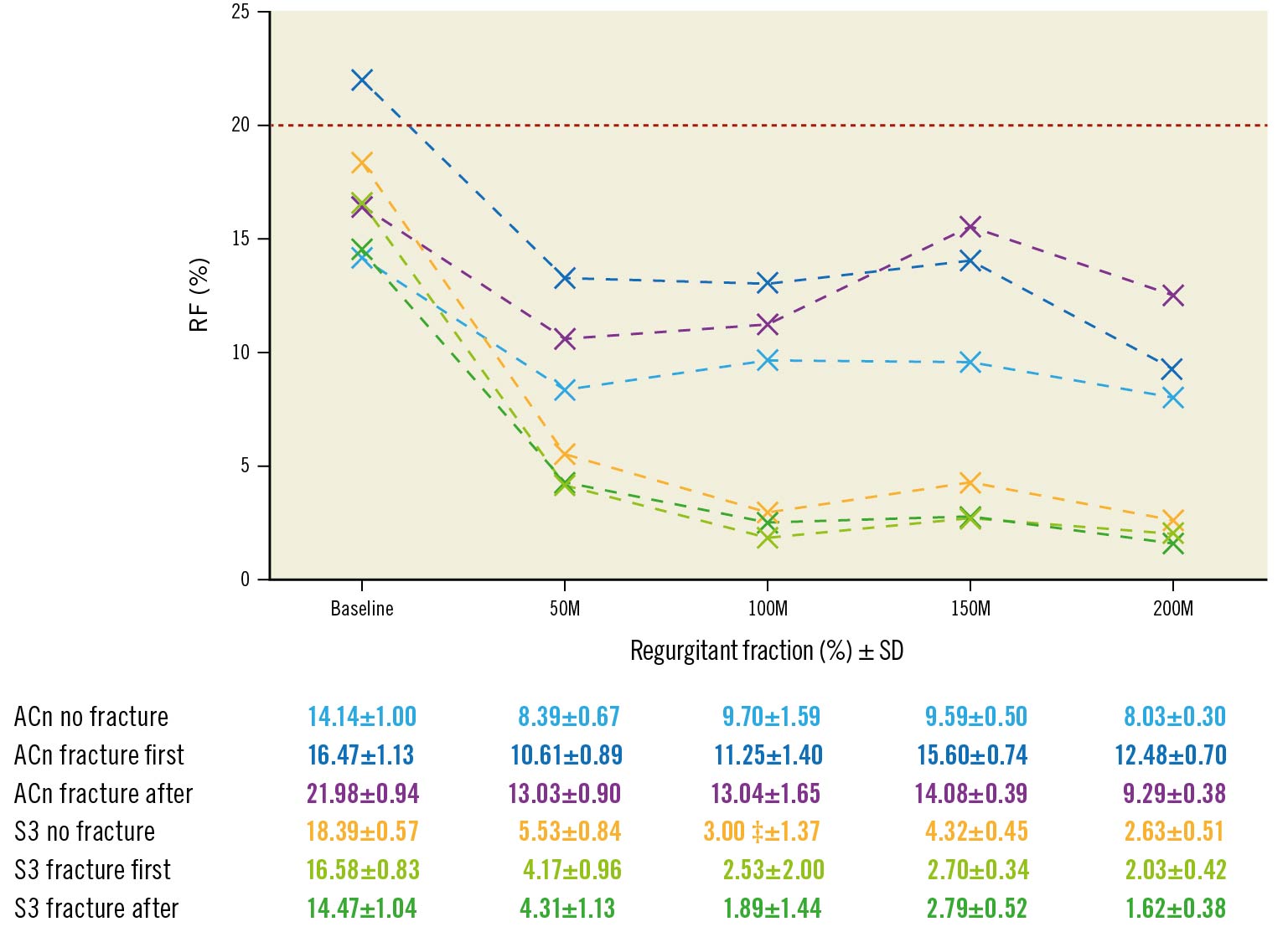
Figure 2. Progression of regurgitant fraction according to BVF timing. Evolution of regurgitant fraction (RF) during accelerated wear testing up to 200M cycles according to BVF timing. The red line (20%) is the limit for acceptable RF according to ISO 2021 guidelines. ACn: ACURATE neo; BVF: bioprosthetic valve fracture; M: million; S3: SAPIEN 3; SD: standard deviation
Effective orifice area
The EOA from baseline up to 200M cycles, assessed at 50M cycle increments, is reported in Figure 3 and Supplementary Figure 1. At 200M cycles, the EOA of the ACn was 1.74±0.01 cm2 (no BVF), 1.97±0.02 cm2 (BVF first) and 2.21±0.02 cm2 (BVF after). For the S3, the EOA at 200M cycles was 1.26±0.01 cm2 (no BVF), 1.65±0.01 cm2 (BVF first) and 2.22±0.01 cm2 (BVF after). Thus, throughout the accelerated wear testing, an increased EOA was maintained in both the ACn and S3 valves when the fracture was performed after ViV.
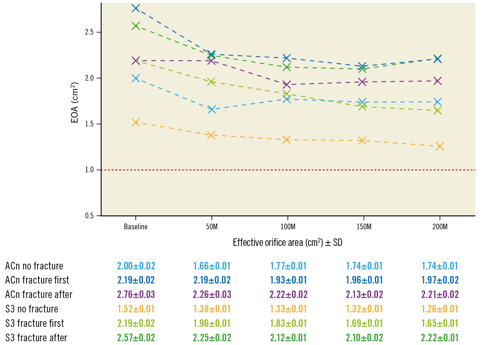
Figure 3. Progression of effective orifice area according to BVF timing. Evolution of effective orifice area (EOA) during accelerated wear testing up to 200M cycles according to BVF timing. The red line represents the limit value of EOA corresponding to severe aortic stenosis. ACn: ACURATE neo; BVF: bioprosthetic valve fracture; M: million; S3: SAPIEN 3; SD: standard deviation
Mean transvalvular gradient
At 200M cycles, the averaged mean gradient for the ACn was 13.42±0.60 mmHg (no BVF), 10.52±0.17 mmHg (BVF first) and 9.28±0.16 mmHg (BVF after). For the S3, the averaged mean gradient at 200M cycles was 23.19±0.24 mmHg (no BVF), 14.02±0.10 mmHg (BVF first) and 8.10±0.05 mmHg (BVF after). Thus, the S3 with no BVF was the only configuration for which the mean gradient increased by almost 10 mmHg and reached a value above 20 mmHg, which is the generally accepted threshold for structural valve deterioration22.
Macroscopic structural valve deterioration
Minor macroscopic damage to the leaflet such as delamination was observed independent of the BVF timing. Some degree of delamination was also observed on the skirt of both the ACn and S3. No holes, tears, gross delamination, peeling, fracture, or excessive deformation were observed.
Histological assessment of leaflet deterioration
At 200M cycles, the histological examination suggested less leaflet ultrastructure damage when BVF was performed after ViV for both the ACn (Figure 4A-Figure 4C) and S3 (Figure 5A-Figure 5C). For the ACn, leaflet thickness was greater when fracture was performed after ViV compared to no fracture (237.5±16 μm vs 201.8±22.8 μm; p=0.0004) (Figure 4D), as well as compared to fracture before ViV (237.5±16 μm vs 221.3 ±22.3 μm; p=0.0314) (Figure 4D). For the S3, the leaflet thickness was numerically greater when fracture was performed after ViV compared to no fracture although this did not reach statistical significance (427.5±36.4 μm vs 407.0±39.7 μm; p=0.1391), and it was significantly higher compared to fracture before ViV (427.5±36.4 μm vs 394.6±53.0 μm; p=0.0132) (Figure 5D). The difference in thickness between the ACn and the S3 is related to the different design of the 2 valves. Analysis of leaflet matrix density, determined by positive pixel counting, showed no difference in the ACn when BVF was performed after ViV compared to BVF before ViV (0.67±0.06 vs 0.64±0.10; p=0.35) but did trend towards significance when compared to controls (p=0.11) (Figure 4E). On the other hand, for the S3, BVF after ViV showed highly significant differences compared to BVF before ViV (0.66±0.11 vs 0.44±0.05; p<0.0001) and to no BVF (p<0.0001) (Figure 5E). Of note, for each group, there was a trend towards a higher positive pixel count on the ventricular side of the leaflet, even if this was not always reaching statistical significance, suggesting greater damage to the aortic valve surfaces (Figure 4F, Figure 5F). Notably, the ACn with no fracture showed extensive histological delamination (Supplementary Figure 2A). In some areas this was isolated to the aortic side of the leaflet (Supplementary Figure 2B), which is similar to the trend of greater damage reflected on the aortic side of the valve by positive pixel counting analysis. Delamination on histology was seen minimally on other valves.
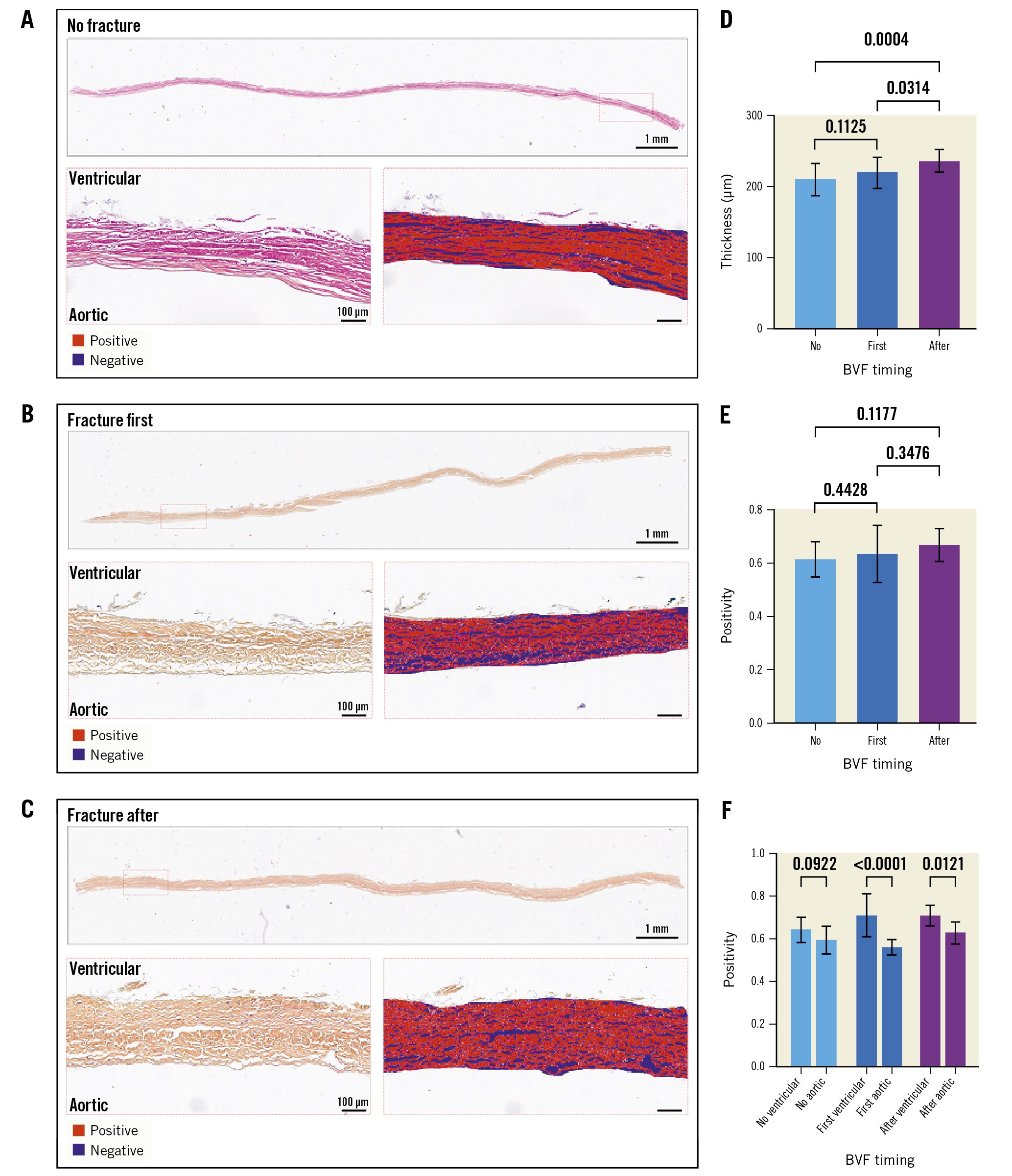
Figure 4. Histological analysis of the ACn leaflets according to timing of fracture. Histological appearance of ACn leaflets when not fractured (A), when fracture is performed before ViV (first) (B), or after ViV (C) showing the whole leaflet length and representative positive pixel count analysis in high resolution inset for A-C. Quantification of leaflet thickness (D), and leaflet density by positive pixel counting for the entire leaflet thickness (E) and segmented into aortic and ventricular aspects of the leaflet (F). ACn: ACURATE neo; BVF: bioprosthetic valve fracture; ViV: valve-in-valve
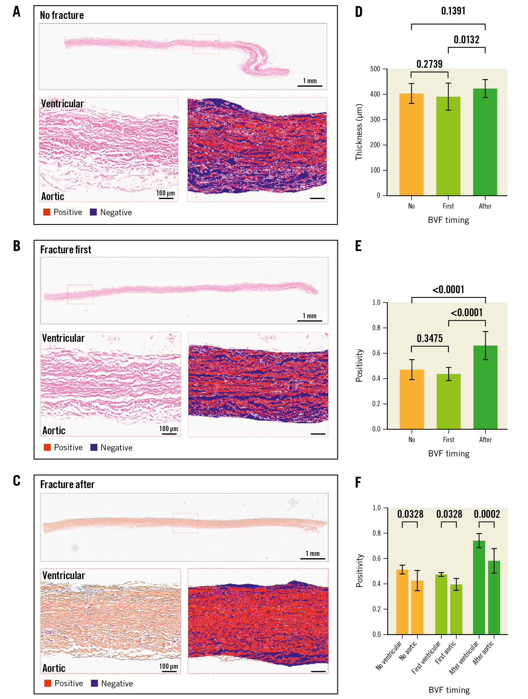
Figure 5. Histological analysis of the S3 leaflets according to timing of fracture. Histological appearance of S3 leaflets when not fractured (A), when fracture is performed before ViV (first) (B) or after ViV (C) showing the whole leaflet length and representative positive pixel count analysis in high resolution inset for A-C. Quantification of leaflet thickness (D) and leaflet density by positive pixel counting for the entire leaflet thickness (E), and segmented into aortic and ventricular aspects of the leaflet (F). BVF: bioprosthetic valve fracture; S3: SAPIEN 3; ViV: valve-in-valve
Second-harmonic generation microscopy analysis
At 200M cycles, SHG image analysis revealed a significantly higher entropy (structural disorganisation of collagen fibres) when BVF was performed after ViV for both valves. Except for the ACn with no fracture, entropy was not significantly different between the ventricular and aortic sides. Figure 6 shows results of the entropy analysis of the leaflets.
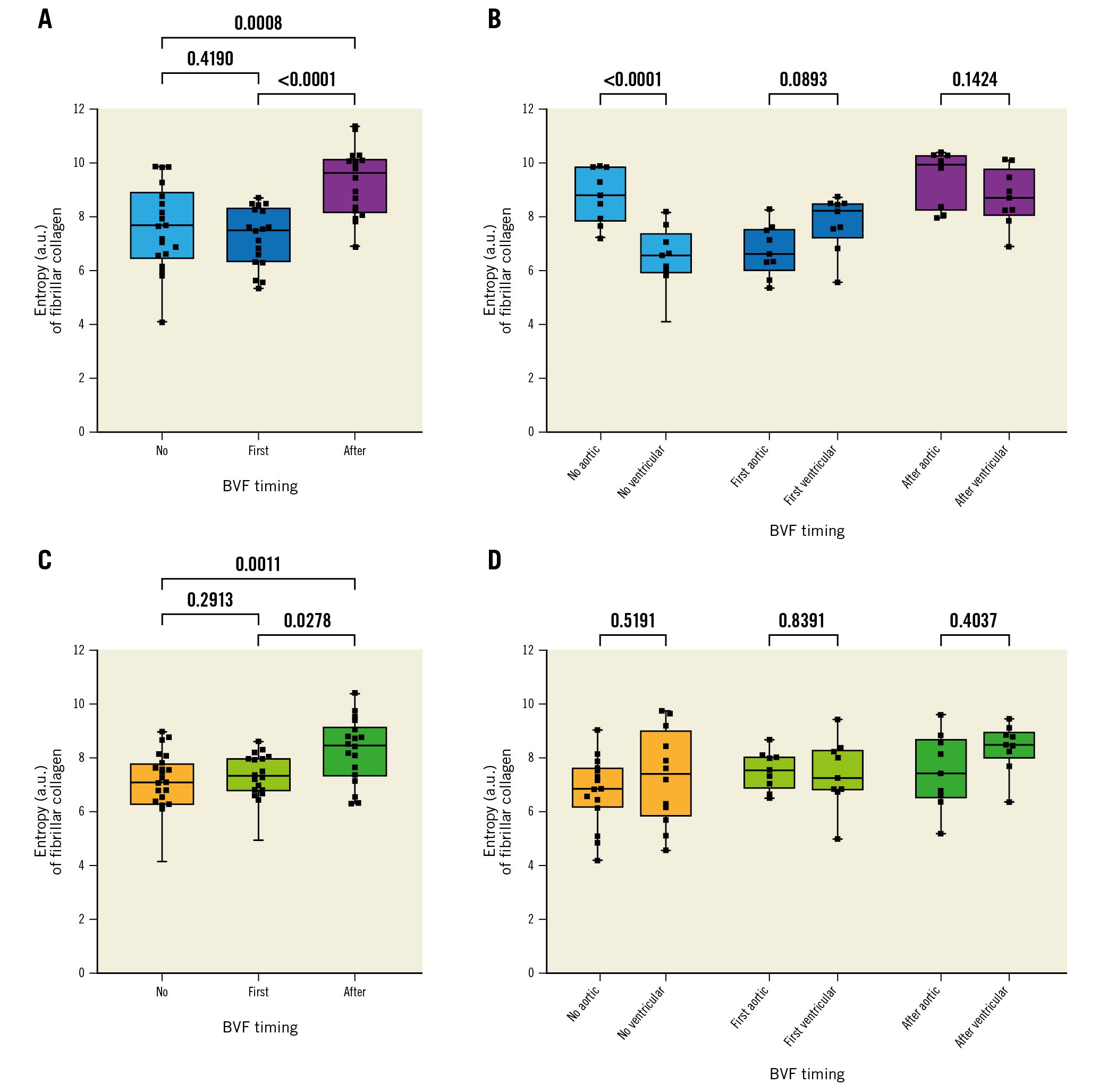
Figure 6. Collagen structure analysis based on SHG microscopy imaging of THV leaflets. Summary of the entropy analysis calculated from SHG images. A higher degree of entropy indicates a higher degree of collagen fibre disorganisation. A) Entropy according to BVF timing in the ACn. B) The same analysis but looking at the ventricular and aortic sides separately. C) Entropy according to BVF timing in the S3. D) The same analysis but looking at the ventricular and aortic sides separately. ACn: ACURATE neo; a.u.: arbitrary units; BVF: bioprosthetic valve fracture; S3: SAPIEN 3; SHG: second-harmonic generation; THV: transcatheter heart valve
Scanning electron microscopy
Overall, at 200M cycles, each timing of fracture resulted in a certain degree of damage on the surface of the leaflet as assessed by SEM. BVF performed after ViV overall resulted in more damage to the collagen on both valves, with a slight predominance on the ventricular side. Moreover, the S3 had an overall higher degree of superficial collagen damage than the ACn. Supplementary Figure 3 and Supplementary Figure 4 show samples of SEM imaging with corresponding damage scores.
Discussion
Whether to perform BVF before or after THV deployment in ViV procedures continues to be a clinical debate. There is indeed a concern that BVF performed before ViV can lead to acute aortic insufficiency with haemodynamic compromise, but it avoids high-pressure balloon inflation on the freshly implanted THV. On the other hand, BVF performed after ViV might ensure better THV expansion, but with it comes the risk of damaging the leaflets of the new THV with unknown long-term consequences.
This study provides insights from the bench to help guide decision-making in the future evolution of this procedure. Compared to BVF performed prior to ViV, BVF after ViV was associated with a higher long-term EOA and lower transvalvular gradient without any trade-off in terms of RF (Central illustration). The S3 demonstrated a lower RF than the ACn throughout testing, and similar EOA and mean gradient when BVF was performed after ViV. Furthermore, this analysis demonstrates an acceptable durability of the ACn and S3 THV after accelerated wear testing up to 200M cycles, which is the equivalent of 5 years following BVF. Thus, this study suggests that the best compromise between RF and EOA was BVF after ViV for both the S3 and the ACn.
Small series of patients have already shown the safety and favourable haemodynamic impact of BVF in the context of ViV interventions. However, data currently published offer only short-term clinical follow-up up to 1 year, while longer-term results are unknown7122324. In lieu of available clinical follow-up, this bench study demonstrates sustained favourable durability to an equivalence of 5 years. It also provides reassuring data regarding concern for potential structural damage to the THV when BVF is performed after ViV. Indeed, only minor structural damage to the valve frame or leaflet was observed at baseline and at 200M cycles.
Additionally, microscopic examination of the leaflet ultrastructure showed improved leaflet structure throughout the leaflet thickness at 200M cycles when BVF was performed after ViV. This is illustrated by a trend for thicker leaflets and an increased positive pixel count. Interestingly, SHG analysis showed a higher degree of collagen disorganisation when BVF was performed after ViV, and SEM revealed similar findings of a higher score of damage in that context. This may appear counterintuitive but is indeed consistent when considering the depth of analysis for each modality. Thus, PPC evaluates the full thickness of the leaflet and our results suggest that BVF performed after ViV leads to better valve expansion with preserved histological structure of the leaflet over time. On the other hand, SHG and SEM only evaluate the very superficial aspects of the leaflets. These results thus suggest that BVF performed after ViV generates a higher degree of superficial collagen damage, likely due to the stretch of the leaflets and pressure against the THV frame, but that this does not translate into overall structural deterioration of the leaflet. Interestingly, depending on the valve type, a differential effect of BVF seems to be observed. Indeed, BVF seemed to have a more pronounced protective effect on the S3 than on the ACn. This is illustrated by a higher relative and absolute gain in the EOA and PPC as well as a more consistent reduction in the RF for the S3 than for the ACn (the trend in PPC difference was not significant for the ACn while it was for the S3). These findings are only hypothesis-generating given the limited sample analysed. However, they do raise a question about the different impact of BVF for tall-frame valves with supra-annular leaflets compared to valves with intra-annular leaflets, whose performance and durability might be more affected by constriction and underexpansion in the absence of BVF. This is supported by the fact that the SEM analysis showed overall more superficial damage on the S3 than the ACn. This suggests that the intra-annular position of the S3 leaflets makes them more prone to compression against the surgical valve and the THV frame during balloon inflation, while the ACn leaflets, being supra-annular, are less subject to this interaction.
Limitations
The main limitation of the present work is the one inherent to bench testing, which is that a bench test is not able to fully reproduce real-life conditions. Additionally, the generalisability of hydrodynamic testing, AWT, as well as of histological, SHG and SEM assessment, is limited by the fact that only 1 sample was available for each testing condition. Thus, these results will need to be replicated in a clinical setting with long-term follow-up of patients treated with BVF with different timing. Nevertheless, in the absence of such data, for now the present study offers some reassuring preclinical data regarding the long-term safety of BVF. It must also be noted that due to the experimental setup, the RF observed here is only related to intervalvular or central leaks and not to paravalvular leak, unlike in real-life conditions where paravalvular leak around the index THV is also possible. Further, AWT only evaluates mechanical wear and does not incorporate other biological factors that can lead to valve degeneration. However, the main concern related to BVF is the use of high-pressure inflation on a freshly implanted THV and the potential damage to the leaflets.
AWT coupled with histological analysis thus seems to adequately capture this phenomenon of mechanical wear. While our focus in this study is on function throughout AWT and leaflet analysis after AWT, it is notable that future studies are needed to assess the acute impact of BVF on leaflet structure and damage in detail using ultrastructure and histological techniques. Additionally, only 1 surgical valve was used, the Mitroflow, which has a relatively low fracture threshold, and it is unclear if these results are applicable to other surgical valves with a higher fracture threshold. It must also be noted that a 23 mm S3 was used in the present work but that currently a 20 mm THV would probably be used in this context. Nevertheless, bench testing allows for systematic and repeated assessment of THV in various procedural settings without any risk for patients as well as accelerated observation of THV ageing. Moreover, similar observations between real-world studies and bench studies have been made, suggesting a certain degree of clinical applicability of bench observations8121314.
Conclusions
In this bench study, the ACn and the S3 showed acceptable hydrodynamic performances after AWT to 200M cycles, equivalent to 5 years, irrespective of BVF timing compared to no fracture. BVF performed after ViV led to a sustained benefit in terms of the EOA, without a negative impact on the long-term RF. BVF performed after ViV resulted in more superficial damage to the leaflets but more preservation of the overall leaflet structure over time.
Impact on daily practice
BVF allows better immediate haemodynamic performance of THV in the context of ViV interventions. Our bench study suggests that BVF performed after ViV offers the largest haemodynamic benefit without any long-term trade-offs in terms of THV performance or structural valve damage. These bench results need to be confirmed in a real-world setting, and their applicability to other THV and surgical valve designs and sizes need to be further demonstrated.
Funding
These analyses were supported by in-kind funding from ViVitro Labs and the Providence Health Care Early Career Award to Stephanie Sellers.
Conflict of interest statement
D. Meier is supported by the Swiss National Science Foundation (grant P2LAP3_199561). M. Akodad has received research funding from Medtronic, Biotronik, and La Federation Française de Cardiologie. A.G. Chatfield is funded by the New Zealand Heart Foundation and John Ormiston Scholarship. D.A. Wood is a consultant to and has received research funding from Edwards Lifesciences and Abbott. JG. Webb is a consultant for Edwards Lifesciences and has received research funding from Medtronic, Boston Scientific, and Edwards Lifesciences. J. Leipsic is supported by a Canadian Research Chair in Advanced Cardiopulmonary Imaging; consults for MVRX, HeartFlow Inc., and Circle Cardiovascular Imaging; and provides CT core lab services for Edwards Lifesciences, Medtronic, Neovasc, Boston Scientific, and Tendyne Holdings, for which no direct compensation is received. J. Sathananthan has received speaking fees from Edwards Lifesciences and NVT Medical; and is a consultant for Edwards Lifesciences, Boston Scientific, Anteris Technologies, and Medtronic. S. Sellers is a consultant to Providence Research, Edwards Lifesciences, and Medtronic. P. Pibarot has received funding from Edwards Lifesciences, Medtronic, Pi-Cardia, and Cardiac Phoenix for echocardiography core laboratory analyses, and research studies in the field of transcatheter valve therapies for which he received no personal compensation; he has received lecture fees from Edwards Lifesciences and Medtronic. A.K. Chhatriwalla is on the speakers bureau of Abbott Vascular, Edwards Lifesciences, and Medtronic; is a proctor for Edwards Lifesciences and Medtronic; and has received research grants from Boston Scientific. L. Sondergaard has received consultant fees and/or institutional research grants from Abbott, Boston Scientific, Medtronic, and SMT. The other authors have no conflicts of interest to declare.
Supplementary data
To read the full content of this article, please download the PDF.