Abstract
Aims: Whereas transthoracic echocardiography is the modality of choice for the diagnosis of severe aortic stenosis and cine-fluoroscopy is used to guide the implantation of the TAVI prosthesis, we believe that multislice computer tomography (MSCT) is the modality of choice for evaluation of the aortic root with a view to selecting patients with suitable anatomy and to guide sizing. We aim to describe an anatomical approach for the step by step interrogation of a 3D MSCT dataset to obtain the measurements of the aortic root required for patient selection, sizing and selection of the optimal angulation of the C-arm during the implantation procedure.
Methods and results: The landmarks used to anatomically define the aortic annulus and structures of the aortic root may be used to define the same structures for measurement on a 3D MSCT dataset by setting up orthogonal cut-planes including one axial to the aortic annulus. This allows true axial diameter measurements and also enables us to define the valve plane.
Conclusions: Measurement on the axial images avoids incorrect diameter measurements that do not pass through the central axis.
Introduction
Transcutaneous aortic valve implantation (TAVI) is a new procedure that is rapidly gaining acceptance for treatment of patients with severe aortic stenosis who are considered to be at high risk for surgical replacement (SAVR)1. At variance with SAVR, the cardiologist does not have a direct vision of the aortic root, the aortic valve and its surrounding structures during TAVI and does not have the sizing probes that surgeons use when selecting prosthesis size. Therefore, a correct understanding of the aortic root and valve and a correct estimation of the various dimensions before TAVI using non-invasive imaging is crucial in the planning of the procedure2.
Whereas transthoracic echocardiography, by providing physiological information, is the modality of choice for the diagnosis of severe aortic stenosis and cine-fluoroscopy is used to guide the implantation of the TAVI prosthesis, we believe that multislice computer tomography (MSCT) is the modality of choice for the evaluation of the aortic root with a view to selecting patients with suitable anatomy and to guide sizing. We describe a systematic approach for the interrogation of a 3D MSCT dataset to obtain the measurements of the aortic root required for patient selection; sizing and selection of the optimal angulation of the C-arm during the implantation procedure.
MSCT acquisition protocol
An MSCT scanner with 64-detectors is recommended for the image acquisition, although more recent dual source scanners have an advantage in this patient population due to the inherently higher temporal resolution (83 ms). With new multi-detector and dual source scanners (128 slices and above) the peripheral vasculature including the subclavian and iliaco-femoral vessels may be acquired with only a small increase in contrast requirement, radiation dose and breath hold time, while image quality is also less affected by heart rate and arrhythmias. Although a proportion of patients with severe aortic stenosis are already on B-blockers, additional doses are not generally given in this population even when the heart rate is somewhat high (>75/min). We use a high tube voltage (120 kV) and the tube current (mAs) is adjusted to the patient’s weight. The detector aperture is set to the thinnest possible detector width (e.g., 0.625 mm) and the reconstruction field of view set to 18 cm, restricted to the structures of interest. Slice coverage should ideally range from the aortic arch to the diaphragm. Reconstruction is performed with a slice thickness of 0.75 mm with 0.4 mm increment. Thicker slices might be acquired in the event of reduced image quality. Because patients eligible for TAVI have a high incidence of arrhythmia, a wide pulsing window (10-50% of the RR-interval) or continuous scanning with retrospective reconstruction is recommended, as this allows manual selection of the optimal reconstruction interval in the event of arrhythmia. The higher radiation exposure resulting from using wide pulsing or continuous scanning is not thought to be clinically relevant due to the advanced age and multiple comorbidities of this patient group. The systolic phase may be most informative in this patient group as aortic valve area can also be measured. However, no difference has been reported in the dimensions of the aortic annulus during systole and diastole in 3D imaging studies3. Therefore, obtaining optimal image quality is the overriding consideration rather than focussing on any specific phase of the cardiac cycle. Should it be necessary to scan younger patients, prospective scanning in the end-systolic phase would be preferable.
Anatomical definitions and relevance to MSCT
The attachment line of the aortic leaflets is crown shaped and the aortic annulus is anatomically defined as the virtual “ring” that has three anchor points at the nadir of each aortic leaflet (the floor of each cusp) (Figure 1)2. The level where the normal aortic root is the widest is defined as the maximum width of the sinuses. The sino-tubular junction is defined as the narrowest section of the ascending aorta above the sinuses, provided that the ascending aorta is not dilated, and corresponds approximately with the virtual ring connecting the commissures i.e., the three points where the attachment lines of adjacent leaflets are joined (Figure 1). In addition to the above, the dimensions of the ascending aorta 4 or 5 cm above the level of the annulus and the heights of the coronary ostia above the annular plane are also included in the matrices for patient selection. Note that the true (histological) ventricular-aortic junction cannot be seen on MSCT or other non-invasive imaging modalities (Figure 1).
These anatomical definitions of the aortic root can be reproduced on an MSCT derived 3D virtual heart by setting up a cut-plane axial to the area of interest (Figure 1).
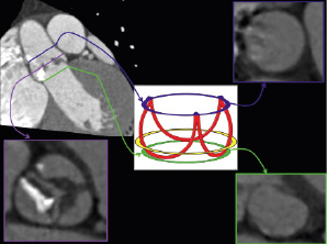
Figure 1. Anatomical definitions of the aortic root and relevance to MSCT. The attachment line of the aortic leaflets is crown shaped and the aortic annulus is anatomically defined as the virtual “ring” that has three anchor points at the nadir of each aortic leaflet (schematic representation, green ring). The level where the normal aortic root is the widest is defined as the maximum width of the sinuses (purple line on MSCT images not indicated on schematic representation). The sino-tubular junction is defined as the narrowest section of the ascending aorta above the sinuses, provided that the ascending aorta is not dilated, and corresponds approximately with the virtual ring connecting the commissures, i.e., the three points where the attachment lines of adjacent leaflets are joined (blue ring). The true (histological) ventricular-aortic junction cannot be seen on MSCT or other non-invasive imaging modalities and the approximate location is indicated by the yellow ring on the schematic representation.
Setting up the viewing planes on MSCT
The MSCT work station (e.g., demonstrated here is the Siemens Circulation, Siemens AG, Munich, Germany) provides three orthogonal windows that are initially oriented respectively sagittal, coronal and axial to the patient’s body (Figure 2). In order to obtain views that are orthogonal to the aortic annulus, the cut planes are first centred on the aortic valve.
The cut lines in the coronal window are then adjusted so that they are more orthogonal to the aortic root, (Figure 2, Panel B). This is followed by making further adjustments in the sagittal (Figure 2, Panel A) and/or the coronal window (Figure 2, Panel B) to the orthogonal cut-lines so that an image is obtained in the axial window where the nadir of each of the three aortic leaflets appears simultaneously, (Figure 2, Panel C). The plane so obtained in the axial window is defined as the annular plane and the level can be marked on the coronal window for future reference.
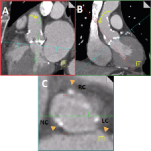
Figure 2. The interface of an MSCT workstation initially provides three views respectively sagittal, coronal and axial to the patient’s body. The cut planes are centred on the aortic valve. Then with the axial window (Panel C) at the level of the base of the aortic root, sequentially the cut planes in the coronal (Panel B) and sagittal (Panel A) windows are adjusted (typically with movement as indicated by the yellow arrows) so that in the nadir of each aortic leaflet appears simultaneously in the axial window (Panel C). The axial window now defines the plane of the aortic annulus (Panel C).
Next, the axial window is shifted in parallel to the annular plane to the level where the leaflet coaptation is best seen, (Figure 3, Panel C). In the axial window the cut-planes are centred on the point where the three leaflets would meet followed by adjustment of the cut planes so that the oblique sagittal plane (Figure 3, red line) cuts through the coaptation line of the non- and left coronary cusps so that the right coronary cusp is divided into two roughly equal halves, (Figure 3, Panel C). The oblique coronal cut-plane (Figure 3 Panel B and green line in panels A and C) then runs through the centre of the aortic valve, and the non- and left coronary cusps. A further explanation follows in the paragraphs below.
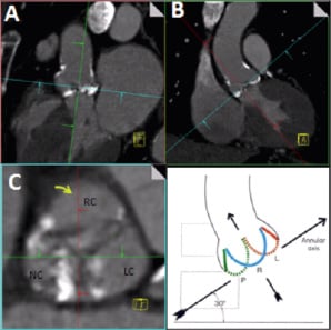
Figure 3. After obtaining the plane of the annulus, the optimal C-arm angulation for the implantation procedure is obtained by adjusting the cut planes in the axial window (Panel C) so that the sagittal plane (red line) passes along the coaptation line of the non- and left coronary cusps and divides the right coronary cusps in two roughly equal halves. The gantry angulation in the oblique coronal view (Panel B) then gives the C-arm angulation where the nadir of all three cusps are on one line with the non-coronary cusp lower left, the left coronary cusp higher and right and the right coronary cusp in the middle. Courtesy of W.A. McAlpine, Heart and Coronary Arteries: An Anatomical Atlas for Clinical Diagnosis, Radiological Investigation, and Surgical Treatment, Springer Verlag, October 1974 for the right lower panel.
Obtaining the optimal C-arm angulation for implantation – the “implanter’s view”
After following the above mentioned steps, the angulation provided in the oblique coronal window (Figure 4, Panel E) corresponds to the optimal C-arm angulation for viewing the aortic root with all three cusps lined up on one level with the non-coronary cusp to the left and lowest, the left coronary cusp to the right and highest and the right coronary cusp in the centre, the so-called “implanters view”, (Figure 4, Panels B and E).
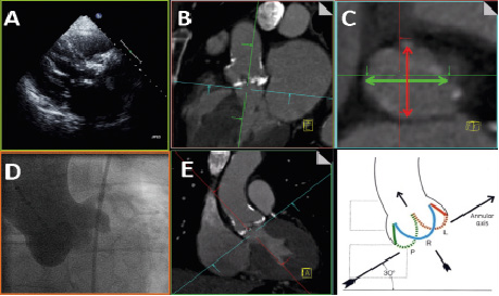
Figure 4. Measures of interest in the axial window and relevance to other imaging modalities. After setting-up the cut-planes as described in the text the angulation provided in the oblique coronal window corresponds to the optimal C-arm angulation for viewing the aortic root with all three cusps lined up on one level (Panels D and E). The oval shape of the annulus is clearly seen on the axial window (Panel C), but cannot easily be appreciated on the oblique sagittal or coronal windows (Panels B, E). On the axial image the oblique sagittal diameter (Panel C, thick red line) corresponds approximately to the measurement obtained from the parastenal long axis view on TTE, Panel A, B (see similarity to panel A when panel B is rotated 90 degrees clockwise). The oblique coronal measurement (Panel C, thick green line) corresponds approximately to the measurement that might be obtained from cine-angiography (Panels D and E). Courtesy to W.A. McAlpine, Heart and Coronary Arteries: An Anatomical Atlas for Clinical Diagnosis, Radiological Investigation, and Surgical Treatment, Springer Verlag, October 1974 for the right lower panel
Measures of interest in the axial window and relevance to other imaging modalities
Annulus
All diameters including those of the aortic annulus are ideally measured on the axial images (see definition of annular plane in previous paragraphs) in order to ensure that the lines of measurement are drawn through the centre of the annulus. Furthermore, the annulus is usually oval in shape and this can not easily be appreciated on the oblique sagittal or coronal windows.3-7
On the axial image the oblique sagittal diameter (Figure 4 C, thick red line) corresponds approximately to the measurement obtained from the parastenal long axis view on TTE, (Figure 4, Panels A and B). The oblique coronal measurement (Figure 4 C, thick red line) corresponds approximately to the measurement that might be obtained from cine-angiography, (Figure 4, Panels D and E).
In two-thirds of patients, setting up the cut-planes as described will give both the minimum (sagittal) and maximum (coronal) annulus diameter, but in a third of patients the true minimum and maximum diameters will be at more oblique angles (Figure 5, Panel B)8.
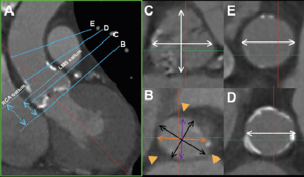
Figure 5. Measurements of interest. In the axial window the oblique sagittal diameter (Panel B, purple line) and the oblique coronal diameter (Panel B, orange line) will respectively give the minimum and maximum diameters of the annulus in approximately two thirds of patients, whereas in another third of patient the true minimum and maximum (Panel B, black lines) will be obtained at more oblique angles8. For example in the images shown the two sets of measurements were 23 mm x 27 mm (Panel B, purple and orange diameters) and 22 mm x 29 mm (Panel B, black diameters) respectively. Axial measurements at the widest level of the sinuses are in a plane parallel to that of the annulus, whereas small adjustments are required to the cut-planes in the coronal and or sagittal windows in order to obtain axial views at the levels of the ST-junction (D) and the ascending aorta (E). The green lines in panels D and E indicate the position of the unadjusted coronal cut-plane (Panel A) at the level of the ST-junction and ascending aorta respectively. On the coronal image the levels where of the annulus and respectively the origins of the left and right coronary ostia are seen on axial images can be marked and thereafter the heights of the coronary ostia above the annulus can be measured (A).
We recommend measuring both the minimum and maximum diameters because of the substantial difference in many patients8. Although current industry guidelines do not recognise the oval shape of the annulus, a pragmatic approach is to use the mean of the minimum and maximum measurements to guide patient selection and sizing8.
Other measures of interest
At the widest point the axial shape of the sinuses resembles a cloverleaf (Figure 5, Panel C and position C in Panel A). Three diameters can be measured along each of the three coaptation lines to the wall of the opposite cusp, of the oblique sagittal and coronal diameters can be measured, (Figure 5, Panel C). The sino-tubular junction diameter is measured at the narrowest section of the ascending aorta above the sinuses (position D on Figure 5 A). In patients with an angulated ascending aorta it may be necessary to make slight adjustments to the cut-planes in the coronal or sagittal windows to ensure true axial measurements, (Figure 5, Panels A and D). Similarly the cut-planes in the coronal or sagittal windows may need to be slightly adjusted to ensure axial diameter measurement of the ascending aorta 40 mm above the annular plane, (Figure 5, Panels A and E). The height of the coronary arteries above the annular plane can be measured as the distance from the annular plane to respectively the planes where the caudal origin of the left and right coronary arteries are seen, (Figure 5, Panel A). This measurement of the height of the coronary ostia on MSCT is clinically similar to open measurement on cadaver hearts9.
An alternative method is to measure the coronary heights on modified oblique coronal or sagittal views10.
A similar approach, using measurements on axial images, may be taken to evaluate the implanted TAVI prosthesis11.
Calcification of the aortic root
Dense calcification of the aortic root and leaflets is ubiquitous in patients referred for TAVI. The calcification can be classified according to Rosenhek12. The potential effects of displacement of calcified leaflets during prosthesis deployment (in contrast to removal of native leaflets during SAVR) have to be considered, (Figure 6).
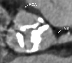
Figure 6. It is unusual to see densely calcified leaflets at or above the origin of the coronary ostia as is shown here. Dense calcification of the aortic leaflets stretching above the mid portion of the left main stem (LMS) and lower border of the right coronary ostium (RCA) may cause occlusion of the coronary ostia following deployment of a percutaneous valve prosthesis, but can be identified during procedural planning using MSCT.
Other pathology
It is important to exclude other pathology that may mimic aortic stenosis for example sub-aortic membranes and clinically relevant septal hypertrophy. These conditions are not common and can usually be readily appreciated on MSCT, (Figure 7).
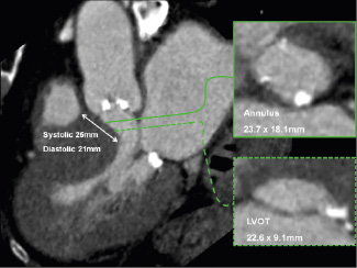
Figure 7. Evaluation of left ventricular outflow tract pathology with MSCT. Oblique sagittal window showing severe left ventricular hypertrophy with on the corresponding axial images narrowing of the left ventricular outflow tract (LVOT: cross-sectional area 1.7 cm2) in a patient with severe aortic stenosis (valve cross-sectional area 0.9 cm2) that was referred for percutaneous valve replacement.
Coronary arteries
The coronary arteries can be evaluated on MSCT of the aortic root in a proportion of patients, but the coronary calcification scores are often very high and scanning parameters may not be optimised for coronary imaging. As a result, both sensitivity and the specificity for the detection of coronary disease will be relatively low.
Incidental findings
Incidental findings are common in the elderly frail patient population who are referred for consideration for TAVI. A system for identifying incidental findings and informing the responsible physician for further management if indicated is necessary.
Peripheral vasculature
Peripheral vascular disease is common in patients referred for TAVI13. A comprehensive evaluation of potential vascular access including the subclavian and or transfemoral routes would include a 3D overview of the vasculature for the evaluation of calcification and tortuosity as well as a review of images axial to the vessels or MPR images in at least two orthogonal planes to allow measurement of minimum diameter and the assessment of stenosis (Figure 8).
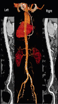
Figure 8: Evaluation of vascular access with MSCT. A 3-dimensional overview demonstrates the distribution of calcium and tortuosity whereas axial or multiplanar orthogonal images allow measurement of the minimum vessel diameter and the identification of stenoses.
Conclusion
While 2D echocardiography provides invaluable physiological data, we believe that MSCT is superior to echocardiography for a detailed and accurate assessment of the morphology in addition to a quantitative assessment of the dimensions of the aortic root. At variance with echocardiography which provides a 2D tomogram of which the angle of the incoming echo beam in relation to the anatomy cannot be fully controlled, MSCT allows a correct and precise orientation of the various anatomic structures. The landmarks used to anatomically define the aortic annulus and structures of the aortic root may be used to define the same structures for measurement on MSCT by setting up orthogonal cut-planes including one axial to the aortic annulus. New 3D-transoesophageal echocardiography imaging techniques also allows axial measurements of aortic root structures, although more published data are needed14. Taking measurements on the axial images of the structures of interest avoids incorrect diameter measurements that do not pass through the central axis. The measurements so obtained from MSCT may guide the selection and implantation of both types of TAVI prostheses that are currently commercially available.
References