Abstract
Background: The novel sirolimus-eluting resorbable scaffold DREAMS 3G was designed as a third-generation development of its predecessor, the Magmaris scaffold.
Aims: This preclinical study aimed to examine the qualitative and temporal course of the degradation of the DREAMS 3G relative to the Magmaris scaffold.
Methods: Forty-nine DREAMS 3G and 24 Magmaris scaffolds were implanted into 48 mini swine for degradation kinetics analysis. Another DREAMS 3G was implanted into one mini swine for crystallinity analysis of the degradation end product after 730 days. Degradation kinetics were determined at 28, 90, 120, 180, and 365 days.
Results: Discontinuity density in DREAMS 3G was significantly lower than that in Magmaris scaffolds for the follow-up timepoints of 90 and 120 days. Planimetric analysis indicated 99.6% backbone degradation for DREAMS 3G at 12 months. Compared to the Magmaris scaffold, individual strut degradation in DREAMS 3G showed less variability and the remaining backbone core was more homogeneous. The degradation end product of DREAMS 3G manifested as calcium phosphate with a minor share of aluminium phosphate.
Conclusions: DREAMS 3G showed almost complete degradation after one year, with amorphous calcium and aluminium phosphate as the end products of degradation. Despite its thinner struts, scaffold discontinuity was significantly lower in the DREAMS 3G than in the Magmaris scaffold, likely providing a longer scaffolding time.
Introduction
Magnesium and its alloys are promising compounds for resorbable implants owing to their light weight and their relatively rapid degradation into benign minerals. Physiologically, this element has an antithrombotic effect and plays a crucial role in maintaining endothelial cell functions12. Based on these outstanding material properties, it is known to exhibit low thrombogenicity, which makes it an excellent candidate as a backbone for bioresorbable scaffolds (BRS). Considering this advantage, resorbable magnesium scaffolds (RMS) have been developed since the late 1990s, and their performance has been improving as a result of device iteration and technical refinement. After extensive research in the manufacturing of magnesium-based BRS technology, BIOTRONIK AG developed a first-generation paclitaxel-eluting RMS adapted from a magnesium alloy, coated with a matrix consisting of polylactic-co-glycolic acid releasing paclitaxel (drug concentration of 7.4 μg/cm2). This was eventually replaced by the Magmaris scaffold (Magmaris is a registered trademark of BIOTRONIK), a second-generation magnesium alloy-based BRS technology, this time releasing sirolimus (drug concentration of 140 μg/cm2) from a bioresorbable poly-L-lactic acid polymer backbone, and was the first European Conformity (CE)-marked magnesium scaffold validated for clinical efficacy and safety3. In a large clinical registry, BIOSOLVE-IV (BIOTRONIKS - Safety and Performance in de Novo Lesion of NatiVE Coronary Arteries With Magmaris- Registry), 2,066 patients were enrolled and implanted with the Magmaris scaffold; they showed incidences of scaffold thrombosis (ScT) and target lesion revascularisation (TLR) of 0.8% and 4.5% at 1 year, respectively (Wlodarczaka et al. Full cohort BIOSOLVE-IV. Euro PCR 2022. Paris, France). In the first cohort of 1,075 patients at 3-year follow-up, the incidence of ScT and clinically driven TLR was 0.6% and 6.8%, respectively (Torzewski et al. Safety and performance of Magmaris at 36-months: BIOSOLVE-IV first cohort. EuroPCR 2022. Paris, France). Thus, this RMS has shown favourable clinical performance, but its mean late lumen loss (LLL) still has room for improvement, mostly with more challenging lesion types4. In this regard, late scaffold recoil was reported to correlate with increased LLL, which may have resulted in TLR5. For the next generation of RMS, a major goal was to further improve the qualitative and quantitative aspects of degradation, which have been suggested to result in homogenous resorption and, consequently, improved temporal stability of the magnesium backbone within the critical time span of vascular healing and remodelling.
The novel sirolimus-eluting RMS named “drug-eluting resorbable magnesium scaffold (DREAMS) 3G” (BIOTRONIK) was designed as a third-generation development of its predecessor model, the Magmaris scaffold. By replacing rare earth elements with aluminium in a proprietary magnesium alloy (BIOmag alloy), the DREAMS 3G has improved mechanical properties over the Magmaris scaffold despite having a thinner-strut thickness compared to its predecessor in all profiles (the strut thickness of the DREAMS 3G varies with the scaffold diameters: 99 μm, 117 μm, and 147 μm for the diameters 2.5 mm, 3.0/3.5 mm, and 4.0 mm, respectively). In addition, the total surface area could also be slightly reduced in this RMS compared to its predecessor (DREAMS 3G: 7.8 mm2 per mm scaffold length vs Magmaris scaffold: 9.2 mm2 per mm scaffold length).
Our group previously reported the basic principles and characterisation of degradation of the Magmaris scaffold in bench-side and preclinical animal studies6. Against this background, we aimed to examine the qualitative and temporal course of degradation of the latest generation of RMS (DREAMS 3G) in healthy, juvenile swine, to enable relative comparison to the benchmark Magmaris scaffold.
Methods
Test and control devices
Supplementary Table 1 shows the characteristics of each scaffold. The test device, DREAMS 3G, refers to the most recent drug-eluting resorbable metal scaffold consisting of a balloon-expandable delivery system carrying a 3.0x18 mm proprietary magnesium alloy (BIOmag alloy, 93.75 percentage by weight [wt%] magnesium plus 6.25 wt% aluminium) scaffold with 6-crown 2-link rectangular-shaped struts at a thickness of 117 μm and width of 150 μm. The BIOlute drug-eluting coating on the scaffold is composed of a bioresorbable poly-L-lactic acid (PLLA) polymer matrix loaded with sirolimus (140 μg/cm2).
The control device, Magmaris RMS (known in its previous iteration as DREAMS 2G; BIOTRONIK), refers to the CE-marked 3.0×20 mm magnesium scaffold with the BIOlute coating and with the same drug density. The strut thickness and width are 150 and 150 μm, respectively.
For crystallinity analysis of the degradation product, DREAMS 3G prototypes (BIOTRONIK) were used that had the final DREAMS 3G backbone (BIOmag alloy) and coating material (BIOlute coating) but the scaffold geometry of the Magmaris RMS.
Animal model
A juvenile porcine coronary stent model was used to assess the quantitative (time course of degradation) and qualitative degradation process. Segments of all three main coronary arteries with favourable anatomy and diameter were selected by angiography at the discretion of the interventionalist, and the devices were implanted targeting a balloon-to-artery ratio of 1.05 to 1.2, as previously described6.
A total of 49 DREAMS 3G and 24 Magmaris RMS were implanted into the coronary arteries of 48 Yucatan mini swine (Supplementary Figure 1). The following timepoints and animal/device numbers were applied: 28 days (14 animals/8 DREAMS 3G/8 Magmaris RMS), 90 days (11/9/8), 120 days (6/8/8) 180 days (8/9/0), 1 year (9/15/0). For the qualitative degradation process, only a subset of the DREAMS 3G scaffolds was analysed (3 per timepoint). After excision, the arteries including the scaffold were immersion-fixed in neutral buffered formalin, processed to 100% glycerol, embedded in polymethylmethacrylate (PMMA), and cut into three blocks after the micro-computed tomography (μCT) analysis.
To investigate the crystallinity of degradation products, a DREAMS 3G prototype was implanted into a coronary artery of one Goettingen mini swine while a non-implanted DREAMS 3G prototype, as well as a naïve artery and a porcine rib bone segment, served as controls. The implanted device was harvested after 730 days to ensure complete degradation of the scaffold; the artery including the scaffold was kept in saline and cooled at 0°C and analysed after transport without freezing and thawing.
Animal husbandry, medication administration, and scaffold implantation were performed according to practice standards as previously reported7. Study protocols were approved by the Institutional Animal Care and Use Committee of the testing facility (Charles River Laboratories Montreal ULC, Boisbriand, Quebec, Canada) and the state administration of Saxony-Anhalt (Germany, 42502-3-763 IMTR) and followed the requirements and guidelines of the commission directive 86/609/EEC, the German Animal Protection Act (version May 18 2006, amended on 9 December 2018) and the Canadian Council on Animal Care regulations.
Discontinuity density by micro-computed tomography
A three-dimensional (3D) model of the (partially) degraded scaffold inside the vessel embedded in PMMA was computed based on X-ray imaging (SKYSCAN 1272, Bruker; resolution: 7.0 μm) of the rotating sample for all follow-up timepoints as previously described6. In brief, based on this 3D visualisation, the number of strut discontinuities of the whole scaffold was determined and divided by the scaffold length to get the discontinuity density (1/mm). All DREAMS 3G and Magmaris scaffold samples up to and including 180 days were analysed for discontinuity density. The interobserver variability for strut discontinuities assessed by μCT was described previously6.
Quantitative analysis of backbone degradation by optical microscopy planimetry
To determine the degree of degradation, the PMMA blocks were polished on one cross-section side, and the individual strut cross-sections were imaged by optical polarised light microscopy (BX51M; Olympus GmbH) that showed a high contrast between the non-degraded metal alloy and degradation product. The initial strut cross-section area (Aini) and the non-degraded metal alloy (Aundeg) were determined with the software OLYMPUS Stream 2.3.2 (EVIDENT) as previously described6.
A total of 260 struts in 24 sections for the DREAMS 3G and 270 struts in 24 sections for the Magmaris scaffold at 28 days, 292 struts in 27 sections for the DREAMS 3G and 256 struts in 24 sections for the Magmaris scaffold at 90 days, 274 struts in 24 sections for the DREAMS 3G and 259 struts in 24 sections for the Magmaris scaffold at 120 days, and 282 struts in 27 sections at 180 days and 439 struts in 45 sections for the DREAMS 3G at 1 year were analysed.
The mean backbone degradation degree per scaffold was calculated via the ratio of summed up partial areas of all strut cross-sections per scaffold: 100% - ΣAundeg/ΣAini.
Variability analysis of degradation per strut cross-section
For the degradation variability analysis per device type and follow-up time of 28, 90, 120, 180 and 365 days, the degradation per individual strut cross-section of DREAMS 3G and Magmaris RMS (where applicable) was used, resulting in individual data points for the degree of degradation per strut.
Inhomogeneity index of degradation per strut cross-section
The inhomogeneity index of degradation per strut cross-section (InID) was established to provide quantitative means in shape uniformity of the remaining metallic magnesium core during degradation. InID was evaluated for each strut of DREAMS 3G and Magmaris RMS designated for quantitative analysis of backbone degradation (full details and exceptions are provided in Supplementary Appendix 1).
Ideally, uniform shapes of Aundeg with equally degraded layer thickness on all four sides result in InID=1, whereas non-uniform shapes of Aundeg, with a minimal width or height within the shape result in InID>1 (Supplementary Figure 2).
Backbone degradation mechanism and products by scanning electron microscopy and energy dispersive X-ray spectroscopy
The elemental composition and morphology of the metallic DREAMS 3G backbone and its degradation products of the PMMA-embedded strut cross-sections were examined by scanning electron microscopy (SEM; EVO LS15; ZEISS; backscattered electron imaging) and energy dispersive X-ray spectroscopy (EDX; XFlash 5010; Bruker; line scans across strut cross-sections with quantification of selected elements of interest and qualitative elemental maps of complete strut cross-sections) analysis with spatial resolution of a few micrometres. Twelve DREAMS 3G samples were analysed at 28-day, 90-day, 180-day and 1-year follow-up (n=3 per timepoint).
Crystallinity of backbone degradation products by X-ray diffraction
X-ray diffraction (XRD) analysis was performed on the DREAMS 3G prototypes (one 2-year in vivo degraded scaffold, and one non-degraded scaffold) and on a naïve artery without scaffold, as well as on a porcine rib bone sample, using a two-dimensional general area detector diffraction system (2D GADDS) with a focusing unit (Bruker AXS GmbH).
Statistical methods
Continuous data are presented as mean±standard deviations if data were normally distributed and as median with interquartile range in case of non-parametric distribution. For the comparison of mean values, a two-sample t-test (Welch’s method) was used but replaced by a non-parametrical Mann-Whitney U Test for non-normal data or too small sample sizes to check normality reliably. For the comparison of variabilities, a Bonett test was used.
All tests were done with Minitab 20.4 Statistical Software (Minitab) and a p-value <0.05 was considered statistically significant.
Results
Discontinuity density by micro-computed tomography
Scaffold discontinuity density was assessed in volumetric low resolution μCT images, where all degradation phases, the original magnesium backbone material, as well as the intermediate products and amorphous calcium phosphate, were visible in a single greyscale image (Figure 1A, Figure 1B). The structural integrity of the DREAMS 3G scaffold marginally decreased with a low mean discontinuity density in the scaffold segments (without connectors) of 0.29 per mm at 28 days, and further progressed with longer follow-up times.
The discontinuity density mean values of DREAMS 3G were significantly lower compared to Magmaris RMS for the follow-up timepoints of 90 days (means of 2.63/mm vs 4.30/mm; p=0.02) and 120 days (2.54/mm vs 3.96/mm; p=0.03) (Figure 1C). At 180 days after implantation, DREAMS 3G showed a discontinuity density of 4.94 per mm.
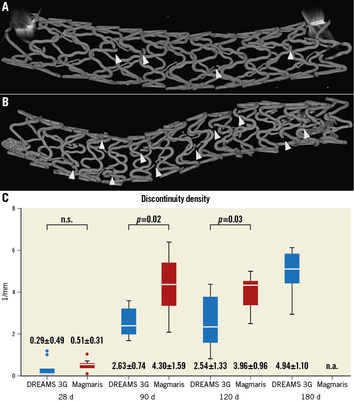
Figure 1. Comparison of discontinuity density. µCT images used for discontinuity density evaluation (indicated by arrowheads) of DREAMS 3G (A) and Magmaris RMS (B) at 90 days after implantation. C) Discontinuity density (1/mm) (without connectors) of individual scaffolds per follow-up timepoint and device group determined by µCT. The numbers represent the “mean±standard deviation” for each item. µCT: micro-computed tomography; d: days; n.a.: not available, n.s.: not significant; RMS: resorbable magnesium scaffold
Quantitative analysis of backbone degradation by optical microscopy planimetry: mean degradation per follow-up timepoint
Quantitative backbone degradation of DREAMS 3G and Magmaris RMS revealed comparable magnesium resorption kinetics that progressed over time, with significant differences seen at 28 days (16.8% and 14.2%; p=0.04) and 120 days (45.7% and 33.5%; p<0.01) (Table 1). At 180 days, 64.9% of the magnesium was resorbed in DREAMS 3G, while at one year, the scaffold was almost completely degraded (99.6%).
Table 1. Backbone degradation (%) of individual scaffolds with mean value and standard deviation per follow-up timepoint and device group determined by optical microscopy planimetry.
| Timepoint | DREAMS 3G | Magmaris RMS | p-value |
|---|---|---|---|
| 28 d | 16.8±5.4% | 14.2±6.8% | 0.04 |
| 90 d | 42.6±7.9% | 37.5±7.8% | 0.31 |
| 120 d | 45.7±6.0% | 33.5±9.0% | <0.01 |
| 180 d | 64.9±4.0% | n.a. | n.a. |
| 365 d | 99.6±0.5% | n.a. | n.a. |
| d: days; n.a.: not available; RMS: resorbable magnesium scaffold | |||
Variability analysis of degradation per strut cross-section
Variability analysis of backbone degradation on a strut cross-sectional level revealed a decreased scattering range of individual data points as well as significantly lower variance (VAR) and standard deviation (SD) in DREAMS 3G compared to Magmaris RMS at 90 and 120 days (DREAMS 3G vs Magmaris RMS: SD 0.21 vs 0.32, VAR: 0.04 vs 0.10; p<0.001 for 90 days; SD: 0.18 vs 0.28, VAR: 0.03 vs 0.08; p<0.001 for 120 days) (Supplementary Figure 3).
Inhomogeneity index of degradation per strut cross-section
The inhomogeneity index (InID) of individual strut cross-sections per follow-up timepoint and device group was evaluated for all struts. For all follow-up timepoints, the InID of DREAMS 3G showed lower mean values and standard deviations than Magmaris RMS (all statistical comparison tests for means and standard deviations: p<0.001; SD: DREAMS 3G vs Magmaris RMS: 28 days: 0.35 vs 0.80, 90 days: 0.16 vs 0.56, 120 days: 0.13 vs 0.70) (Figure 2), indicating more uniform degradation of the backbone in DREAMS 3G versus Magmaris RMS.
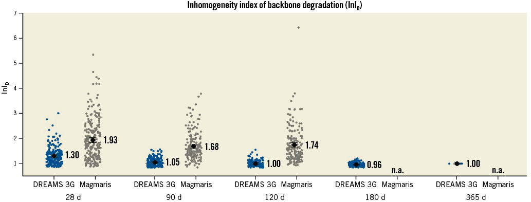
Figure 2. Inhomogeneity index of backbone degradation of individual strut cross-section including mean value and 95 % confidence interval per follow-up timepoint and device group determined by optical microscopy planimetry. d: days; n.a.: not available.
Crystallinity of backbone degradation products by X-ray diffraction
The characterisation of crystalline phases was evaluated using X-ray diffraction analysis of DREAMS 3G prototypes at 2 years after implantation. XRD patterns revealed an absence of any crystalline phases in the completely degraded scaffold (except for a small peak of the polymer-drug coating) and in the naïve artery without scaffold (Figure 3, violet and blue patterns). In contrast, a control device (non-implanted DREAMS 3G prototype), as well as a porcine bone sample, showed characteristic peaks of either metallic magnesium or mineral apatite (a crystalline calcium phosphate derivate), respectively (Figure 3, red and green patterns).
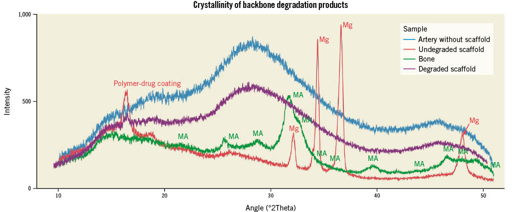
Figure 3. Overlaid XRD patterns of naïve artery without scaffold (blue), non-degraded DREAMS 3G prototype scaffold (red, characteristic crystalline peak positions for metallic magnesium are indicated with Mg), porcine bone sample (green, characteristic crystalline peak positions for mineral apatite are indicated with MA), and two-year in vivo degraded DREAMS 3G prototype scaffold (violet).
Backbone degradation mechanism and products by scanning electron microscopy and energy dispersive X-ray spectroscopy
Selected backscattered electron images and EDX elemental mappings of DREAMS 3G strut cross-sections during and after full degradation using pseudo-colour visualisation of the main elements are shown in Figure 4.
The depicted EDX mapping images are raw data without correction for matrix effects and each element’s intensity is scaled to its maximum for each image individually. Both during and after full degradation of the DREAMS 3G scaffold, the degradation product appeared to be a calcium- and phosphate-rich material, evenly distributed over the entire strut footprint. Meanwhile, the residual magnesium decreased significantly in the degradation product compared to the undegraded core.
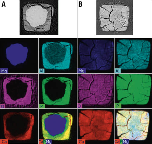
Figure 4. Qualitative elemental mappings by SEM/EDX of representative DREAMS 3G strut cross-sections for: A) 90 days; and B) 365 days. Top line: Backscattered electron images. Bottom right of each column: Overlay images of selected constituents: Ca (red), P (green), Mg (blue). Qualitative data for illustrative purposes only; EDX mapping images are raw data without correction for matrix effects and each element’s intensity is scaled to its maximum for each image individually. It is to be noted, that in the non-degraded BIOmag alloy, the aluminium signal is erroneously low due to uncorrected absorption (different weight per volume of matrix and difficulty in quantification of the aluminium peak due to closeness of intense Mg peak as the main component of the alloy). Ca: calcium; EDX: energy dispersive X-ray analysis; Mg: magnesium; P: phosphorus; SEM: scanning electron microscopy
Discussion
The present study aimed to investigate the qualitative and temporal course of degradation of the DREAMS 3G bioresorbable scaffold in healthy juvenile swine. In this regard, the main findings can be described as follows:
- (i) DREAMS 3G showed overall decreased discontinuity density compared to Magmaris RMS, which reached significance at 90 and 120 days.
- (ii) Cross-sectional planimetry of DREAMS 3G revealed comparable degradation kinetics compared to Magmaris RMS with almost complete degradation at one year.
- (iii) Compared to Magmaris RMS, individual strut degradation showed less variability and was more homogeneous with regards to uniform shapes of the remaining magnesium core on a cross-sectional level in DREAMS 3G.
- (iv) The final degradation product of DREAMS 3G is amorphous calcium phosphate with a high water content, plus a minor share of aluminium phosphate.
Degradation mechanism and products
Elemental mass percentage ratios from quantified line scans, combined with chemical theoretical considerations based on availability of ions in vivo and solubility tables, lead to the assumption that the final degradation product comprises a combination of amorphous calcium phosphate (or a derivative of the latter, possibly containing a share of magnesium instead of calcium, especially in early stages of the process) and a minor share of aluminium phosphate. However, other anions (hydroxides, oxides, or carbonates) may still contribute to the degradation product. For aluminium, there is no evidence of redistribution or migration beyond the strut borders during one year within the sensitivity limits of EDX analysis. Furthermore, high water content of the degradation product can be inferred from its low density (as visible in SEM backscattered electron images) and its open morphology that allows for percolation (concluded from microstructure analysis).
Figure 5 shows simplified assumed reaction pathways of the degradation of the DREAMS 3G alloy (BIOmag alloy). Since a pure hydroxide phase without phosphorus is not observed for DREAMS 3G (in contrast to Magmaris RMS6), a direct precipitation of phosphates (aluminium phosphate and magnesium phosphate, but, partly, also directly calcium phosphate), driven by the reaction of magnesium with water, is assumed to be the main reaction path; this is dependent on the local availability of hydrogen phosphate ions and calcium ions.

Figure 5. Simplified degradation mechanism and justifiably assumed degradation products for DREAMS 3G (reaction pathways). Al: aluminium; Ca: calcium; HPO42- : hydrogen phosphate; Mg: magnesium
Strut discontinuity and mechanical performance of DREAMS 3G
DREAMS 3G was designed as a third-generation development of its predecessor, Magmaris RMS, with the intention to maintain the overall resorption time of approximately 1 year, but to reduce strut thickness, while improving radial strength and scaffolding time to avoid premature collapse during critical phases of vascular remodelling by replacing rare earth elements with aluminium in the alloy. In this regard, a prolonged integrity of the magnesium scaffold could be achieved, as DREAMS 3G had significantly less scaffold discontinuity density than Magmaris RMS at the follow-up timepoints of 90 and 120 days in a porcine coronary model. Despite a faster pace of degradation evaluated by planimetry, which reflects the overall time course of cross-sectional strut degradation, DREAMS 3G exhibited more homogenous and uniform shapes of the remaining metallic magnesium cores and, overall, decreased variability in strut degradation. As a consequence, individual breaks in stent struts relevant for backbone integrity were reduced, which resulted in lower strut discontinuity density relative to Magmaris RMS despite lower strut thickness (Figure 6). In addition, refinement of backbone material with proprietary magnesium alloy enabled scaffold manufacturing with increased stability and radial strength, which may eventually result in improved clinical performance.
Scaffold discontinuity is an inherent and intended phenomenon in RMS that is not observed with permanent metallic stents. It weakens radial strength by disrupting strut continuity and overall stent geometry. Ueki et al investigated the mechanism of restenosis cases in Magmaris RMS using optical coherence tomography, which indicated a significant correlation between LLL and late scaffold recoil5. Notably, greater late recoil was observed in fibrotic plaques than in lipid or calcified plaques. Since fibrous plaques are predominantly composed of smooth muscle cells and extracellular matrix rich in collagenous and elastic fibres, dilatation of such lesions leads to significant vessel stretch, and, in consequence, to increased chronic force exerted on the scaffold. Subsequently, increased radial strength and a longer scaffolding ability is required to withstand constrictive vessel forces in the early period of vascular remodelling following scaffold implantation. While the exact duration of this critical phase remains to be determined, experience from clinical studies with the Magmaris scaffold8 suggested that increasing the mean scaffolding time may also result in an improved outcome in more challenging plaque compositions, such as fibrotic plaques.

Figure 6. Schematic illustration of reduced discontinuity density of DREAMS 3G versus Magmaris RMS despite lower strut thickness and similar degradation kinetics. More homogenous and uniform shapes of the remaining metallic magnesium core in DREAMS 3G (A) versus Magmaris RMS (B) plus overall decreased variability in strut degradation in DREAMS 3G (C) versus Magmaris RMS (D) plus inherently improved material properties of the BIOmag alloy versus the Magmaris RMS alloy (E) resulting in a reduced discontinuity density of DREAMS 3G (F) versus Magmaris RMS (G) as evaluated by µCT. µCT: micro-computed tomography; RMS: resorbable magnesium scaffold
Temporal course of scaffold degradation
Planimetric analysis of the cross-sectional strut corrosion area revealed that approximately two-thirds of stent struts were degraded by 180 days, while almost complete degradation was achieved at 365 days. DREAMS 3G showed more advanced degradation than Magmaris RMS at 28 and 120 days after implantation in the present study. Our group previously reported backbone degradation of 66.5% and 94.8% for Magmaris RMS at 180 and 365 days, respectively6 (DREAMS 3G in the present study showed 64.9% and 99.6% at 6 and 12 months, respectively), indicating that these two RMS have a comparable overall resorption time. Although DREAMS 3G degrades faster in the early phase compared to the Magmaris scaffold, the new RMS showed fewer discontinuities despite its thinner struts. This finding may be explained by both improved inherent material properties (tensile strength) for the alloy used in DREAMS 3G and a more homogeneous degradation with sustained strut integrity, despite the faster degradation progress in the early phase after implantation.
Compared to the Absorb bioresorbable vascular scaffold (Absorb BVS; Abbott Vascular), which required 36 to 42 months for full resorption9, DREAMS 3G has a much shorter resorption time. In a study identifying the causes of late/very late ScT of the Absorb BVS, strut malapposition was the most common finding in cases with late/very late ScT followed by late scaffold discontinuity10. Considering the feature of almost complete strut degradation in DREAMS 3G at 12 months, its short resorption time may positively affect long-term clinical performance. Along these lines, prolonged resorption time beyond the required time frame of vascular remodelling may limit the benefits of BRS technology; this prolongation may result in sustained local foreign body reactions and inflammation, caging of the vessel, and an increased possibility of late scaffold discontinuities. In addition, a longer resorption time may require prolonged dual antiplatelet therapy following BRS implantation. In this regard, DREAMS 3G achieved comparable complete resorption time to Magmaris RMS despite its prolonged scaffolding time. However, it should be noted that validation in clinical trials is needed to determine whether this novel RMS exhibits improved clinical performance.
Limitations
This study was performed in non-diseased juvenile porcine coronary arteries, thereby making translation to human disease conditions difficult. Since there is an absence of stenosis with atherosclerotic disease, the temporal course of degradation and strut discontinuity density may not be directly extrapolated to clinical conditions.
The results of degradation kinetics should also be interpreted carefully since their translation into human patients is uncertain. However, previous Magmaris RMS studies showed the difference in degradation kinetics was minimal among humans and pigs. Since major components of the scaffold alloy remained unmodified during the transition from Magmaris RMS to DREAMS 3G (93.75 wt% vs 93.0 wt% of magnesium, respectively), the differences in degradation kinetics are expected to remain minimal among humans and pigs.
Since Magmaris RMS was investigated as a control scaffold regarding the temporary scaffolding behaviour and not as a target scaffold of this study, its discontinuity density and backbone degradation could be evaluated only for up to 120 days. Hence, whether our findings are consistent in a chronic phase such as 180 and 365 days after the implantation has not been validated. In addition, this study did not assess the scaffold discontinuity immediately after the procedure. Therefore, our results might not reflect the scaffold injury at the time of implantation.
Conclusions
DREAMS 3G showed almost complete degradation at one year after implantation in porcine coronary arteries, with amorphous calcium phosphate with a minor share of aluminium phosphate as the final end-product of degradation. Scaffold discontinuity density was significantly lower in DREAMS 3G than in Magmaris RMS, despite its thinner struts. Clinical validation is required to translate these results into the clinical setting.
Impact on daily practice
DREAMS 3G was designed as a third-generation development of its predecessor, Magmaris RMS, with the intention to reduce strut thickness, while improving radial strength and scaffolding time to avoid premature collapse during critical phases of vascular remodelling. Indeed, less scaffold discontinuity was observed in DREAMS 3G than in Magmaris RMS despite its thinner struts, likely improving its clinical performance.
Acknowledgements
We are grateful for the support of Charles River Laboratories, Montréal, Canada.
Funding
The study was funded by BIOTRONIK AG, Bülach, Switzerland.
Conflict of interest statement
P. Baumann-Zumstein is an employee of BIOTRONIK AG. A. Fubel is an employee of BIOTRONIK AG. M. Haude reports study grants and personal fees from BIOTRONIK, Cardiac Dimensions, and OrbusNeich. R Waksman reports serving on an advisory board for Abbott Vascular, Boston Scientific, Medtronic, Philips, and Pi-Cardia Ltd.; is a consultant for Abbott Vascular, BIOTRONIK, Boston Scientific, Cordis, Medtronic, Philips, Pi-Cardia Ltd., SIS Medical AG, Transmural Systems Inc., and Venous MedTech; has received grant support from BIOTRONIK, Boston Scientific, Chiesi, Medtronic, and Philips; and has investments in MedAlliance and Transmural Systems. M. Joner reports personal fees from Abbott, AstraZeneca, BIOTRONIK, OrbusNeich, ReCor, and Shockwave; grants and personal fees from Boston Scientific and Edwards Lifesciences; personal fees and a grant from Cardiac Dimensions; and a grant from Infraredx, outside the submitted work. S. Galli reports personal fees from BIOTRONIK. M. Seguchi has no conflicts of interest to declare.
Supplementary data
To read the full content of this article, please download the PDF.
