
Abstract
Aims: This document aims to describe a standardised methodology for performing left atrial appendage occlusion (LAAO) using the AMPLATZER Amulet device, and to provide useful tips and tricks for operators with different levels of experience.
Methods and results: Physicians who are experts in LAAO and had personal clinical experience with the AMPLATZER Amulet device were asked to contribute in the preparation of this consensus document. Twenty-seven physicians (20 interventional cardiologists and 7 electrophysiologists) from 14 different countries reviewed the manuscript. A step-by-step approach, simulating a real case, was followed. Starting with patient selection and planning, related cardiac imaging is discussed, followed by vascular access – transseptal puncture optimisation. Then, angiographic calibration/sizing and the required fluoroscopy views are explained and a device sizing strategy is proposed. Device preparation and de-airing is briefly described, followed by sheath exchange, device deployment steps, evaluation of device stability and decision for final release. The way to recapture and change a device is then shown, together with some additional tips on how to deal with challenging anatomies like “chicken wing” left atrial appendage. Finally, for operators who are switching from AMPLATZER Cardiac Plug to Amulet, the main differences between the two devices with respect to implantation technique are presented.
Conclusions: In conclusion, this document reflects a consensus approach by expert implanters on the steps of LAAO technique and best practices for implantation of the AMPLATZER Amulet device, along with some practical tips to minimise the complication rate.
Introduction
Percutaneous left atrial appendage occlusion (LAAO) is a device-based therapy for the prevention of stroke in patients with non-valvular atrial fibrillation (AF)1-14. Worldwide acceptance of LAAO therapy as an alternative to oral anticoagulation (OAC) is growing. However, LAAO is recognised as a technically demanding procedure, requiring rigorous training and skills in order to reduce complications15. The AMPLATZER™ Amulet™ (St. Jude Medical, St. Paul, MN, USA), a second-generation device which has replaced the AMPLATZER™ Cardiac Plug (ACP) (St. Jude Medical), is currently one of the most commonly used devices for LAAO16-19. This document reflects a consensus approach by expert implanters on the steps of the LAAO technique and best practices for implantation of the AMPLATZER Amulet, along with some practical tips to minimise the complication rate. It is targeted both at beginners and at experienced operators with the main focus being on procedural safety. The technique described herein may be modified according to operator experience and preference and according to institution logistics.
Device description
The AMPLATZER Amulet is a self-expanding device made of nitinol that has a distal lobe and a proximal disc, connected by an articulated waist (Figure 1). The device lobe has six to 10 pairs of stabilising wires and is meant to be implanted in the proximal 10-15 mm of the left atrial appendage (LAA), whereas the device disc is intended to cover the ostium at the left atrial side. The proximal female screw is recessed to minimise thrombus formation on the disc and potentially facilitate re-attachment of the device to the pusher screw. The lobe sizes range from 16 to 34 mm (Figure 2). Details of the device characteristics have been previously published16. The design and the implantation technique of the AMPLATZER Amulet are similar but not identical to those of the ACP.
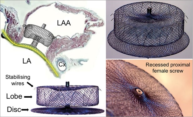
Figure 1. The AMPLATZER Amulet device: main components and mechanism of action. The main components of the AMPLATZER Amulet device are the lobe and the disc. The lobe is implanted into the LAA neck, 12-15 mm from the LAA ostium, and its role is to anchor the device and close the LAA neck. It is self-expanding, so in order to sit tight it needs to be slightly compressed. In addition, the lobe has six to 10 pairs of stabilising wires around its distal perimeter. The disc covers the LAA ostium at the atrial side. Proper apposition of the disc and creation of continuity (yellow line) with the atrial walls allows faster endocardialisation and complete LAA closure at a second, more proximal level. LA: left atrium; LAA: left atrial appendage; Cx: left circumflex coronary artery
Patient selection and planning
The most common indication for LAAO with the ACP and the AMPLATZER Amulet is previous bleeding or high risk of bleeding in patients with non-valvular AF needing OAC therapy9,20. The most important exclusion criterion for LAAO with any device is the presence of thrombus in the left atrium (LA) or the LAA. In such cases, typically the patient is treated with low molecular weight heparin or OAC for at least four weeks and the procedure is performed only once the thrombus has resolved. Logistically, it is beneficial to exclude a thrombus by a pre-procedural transoesophageal echocardiography (TEE)21 or computed tomography (CT) scan22 shortly before the implantation. Thrombi in the LAA, however, are rare and ad hoc LAAO may make sense under certain circumstances23. LAAO is also contraindicated in the presence of active endocarditis or other infections. Another uncommon exclusion criterion is extreme LAA dimensions. The AMPLATZER Amulet is suitable for LAA landing zone (neck) diameters between 11 and 31 mm and the LAA depth should be ≥12 mm (Figure 2)16. The number or the size of the LAA lobes or any anatomic variation that does not include the proximal 10-15 mm is of little relevance in LAAO with the AMPLATZER Amulet. Moreover, double device closures have been described24.
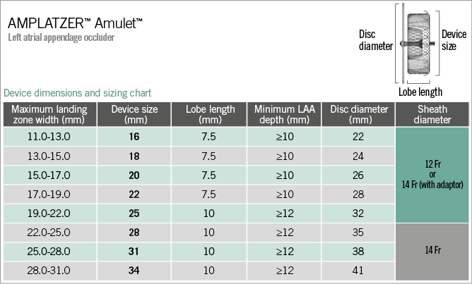
Figure 2. The AMPLATZER Amulet device dimensions and sizing chart. Fr: French (0.33 mm); LAA: left atrial appendage
In the cardiac catheterisation laboratory
Generally, general anaesthesia or at least conscious sedation is used for the procedure, due to the discomfort caused by the use of intraprocedural TEE for guidance21. At the beginning, TEE is performed to exclude thrombus, to detect any pericardial effusion prior to the procedure, and to evaluate the function of the mitral valve and the patency of the left upper pulmonary vein (LUPV). Since cardiac tamponade is a potential complication, it may be of benefit to establish an invasive (femoral or radial) arterial pressure monitoring with heart rate sound in order to detect and remedy haemodynamic instability rapidly.
Depending on the clinical condition of the patient (left ventricular function, mitral regurgitation, and pulmonary pressures), it may be advisable to administer 500-1,000 cc of saline prior to TEE measurements in order to increase mean left atrial pressure to >10 mmHg, reducing the likelihood of inadequate LAA filling and minimising the risk of device undersizing and subsequent embolisation. Then, the TEE operator obtains the baseline LAA measurements (or confirms the measurements obtained during patient screening). The LAA is scanned from 0° to 135° and the maximum and minimum diameters of the ostium and the landing zone are recorded. The TEE operator should be familiar with the implantation technique and device characteristics.
Currently, real-time 3D TEE is used more frequently for assessing the LAA during the implantation procedure25-27. Real-time 3D TEE allows better spatial visualisation of the LAA and more comprehensive evaluation of the device during the procedure (Figure 3). Studies comparing 2D TEE with real-time 3D TEE have shown that real-time 3D TEE is more accurate and reproducible than 2D TEE for the assessment of the LAA orifice size (Figure 3A, Figure 3B)28. Furthermore, with 3D TEE the device may be visualised more completely during the tug test and after deployment (Figure 3C, Figure 3D).
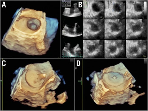
Figure 3. Three-dimensional TEE. Three-dimensional TEE is valuable for the evaluation of the LAA. The LAA orifice shape (A) and the dimensions of the LAA orifice and “body” at different distances from the orifice (B) can be demonstrated in real time. The AMPLATZER Amulet can be visualised during the tug test (C) or after device release (D). LAA: left atrial appendage; TEE: transoesophageal echocardiography
An alternative to TEE is intracardiac echocardiography (ICE), which has the advantage of avoiding the need for general anaesthesia or sedation29,30. The ICE catheter can be introduced from the ipsilateral or contralateral femoral vein and placed in the right atrium, LA, main or left pulmonary artery, or coronary sinus. However, ICE currently lacks multiplanar capabilities, has a lower accuracy in ruling out thrombus, and may provide suboptimal images of the LAA. However, the ability to move the probe in a different position near the LAA (left atrium, main/left pulmonary artery or left coronary sinus) may compensate for the lack of multiplanar views18.
Vascular access – transseptal puncture
Femoral venous access is obtained in the right femoral vein. A 3-4 mm skin incision and perhaps subcutaneous separation of the access site are done to ease advancement of the transseptal and delivery sheath. Some operators prefer to use a short 12-16 Fr introducer for the groin. Transseptal puncture (TSP) is performed under fluoroscopic and preferably TEE guidance in the inferoposterior portion of the fossa ovalis using, e.g., a BRK-1™ needle (St. Jude Medical) which usually provides adequate support and proper angulation for accurate puncture. Other systems are available and used with excellent success. TSP at the optimal puncture site is important to facilitate proper orientation of the delivery sheath in relation to the LAA. In this respect TEE guidance of TSP is instrumental. The TEE operator initially provides a bicaval view, to show the superior and inferior portion of the fossa. This view allows the operator to place the transseptal needle at the inferior axis of the fossa. Once tenting of the atrial septum has been observed, the TEE operator switches the view to a short-axis aortic view to show the anterior and posterior axis of the fossa. In this view the position of the transseptal sheath may be corrected to ensure a posterior puncture. A 3D TEE probe may allow the use of biplanar views showing the inferior and posterior axes of the atrial septum at the same time (x-plane). A PFO may be used for LAAO31. However, it may result in more challenging delivery sheath orientation due to the superior entrance into the left atrium. The majority of operators prefer a directed inferoposterior transseptal approach. If the interatrial septum is thick and difficult to puncture, the needle stylet or diathermy may help. Radiofrequency puncture needles are also available.
Administration of unfractionated heparin is required, targeting an activated clotting time (ACT) of 250-300 seconds. The initial dose is 100 IU/kg. The timing of heparinisation varies. Some operators administer the complete dosage before, others only half of the dosage before and the remaining half after successful TSP. Some give the full dosage only after TSP. The half dose approach is a good compromise as it provides some antithrombotic protection in case of a difficult or prolonged TSP. Once access to the LA has been attained, it is of paramount importance to ensure adequate anticoagulation to avoid thrombus formation on wires and on or in catheters within the thrombogenic environment of the fibrillating LA. Adequate and regular flushing of the catheters serves the same purpose.
LAA angiographic calibration and sizing – fluoroscopy views
A 5-6 Fr pigtail marker catheter may be advanced through the transseptal sheath into the LAA, and a selective injection of contrast may be carried out through the sheath in a right anterior oblique (RAO) 30°/cranial 20° view (the use of a pigtail catheter is a safe way to explore the LAA and is recommended for less experienced operators). To obtain a selective LAA injection, the tip of the sheath should be advanced at the level of the LAA ostium and contrast medium injected through the sheath. In this view, the LAA ostium and neck are usually clearly depicted (Figure 4A). A second angiogram is typically performed in an RAO 30°/caudal 20° view in order to have an orthogonal assessment (Figure 4B). In this view, the ostium (i.e., the transition between LA and LAA) may not be easily visible but the distal part of the LAA is seen. The RAO 30°/cranial 20° and the RAO 30°/caudal 20° views usually correspond to the 45-60° and 135° TEE views, respectively. In case of suboptimal imaging based on the standard views, other projections may be required. Baseline CT allows detailed pre-procedural evaluation of the LAA and can save time (and contrast medium) in case of difficult anatomies (Figure 4C- Figure 4F). Moreover, it can predict the optimal projection for the fluoroscopic working view22.
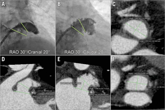
Figure 4. Baseline angiographic views and CT analysis. The baseline angiographic views are RAO 30°/cranial 10-20° (A) and RAO 30°/caudal 10-20° (B). The dimensions of the LAA ostium and neck are measured (green lines). Multiplanar CT reconstruction can provide images of high quality in either short-axis (C, F) or long-axis views (D, E). CT: computed tomography; LAA: left atrial appendage; RAO: right anterior oblique
Device sizing
Optimal device sizing is critical for the procedure in order to avoid device embolisation, incomplete LAA closure, or multiple recaptures and repositioning of the device, prolonging the procedure32,33. Device sizing is customarily based on multimodality imaging. Baseline CT angiography of adequate quality is an accurate method due to its high spatial resolution and 3D capabilities. It needs to be carried out under adequate volume loading of the patient (Figure 4)22. TEE, 3D TEE21, and ICE29,30 have lower spatial resolution but have the advantage of real-time evaluation during the implantation procedure. Angiography in the described views is mandatory. Calibration has to be accurate. Noteworthy, autocalibration or calibration based on catheter diameters may be imprecise, leading to missizing. French sizes (1 Fr=0.33 mm) of sheaths refer to the inner lumen, whereas those of catheters refer to the outer diameter. Finally, it is important to choose the frame depicting the maximum LAA distention.
Similar to the ACP, the AMPLATZER Amulet needs to be oversized in relation to the dimensions of the landing zone. Before deciding upon the degree of oversizing, it is important to define the exact LAA neck diameter. Based on experience with other structural heart disease interventions (i.e., TAVI), it seems reasonable to calculate the mean LAA neck diameter (either by maximum/minimum or perimeter or area) and to choose the device size in relation to that. The rationale for this approach is the following: in circular anatomies the largest diameter equals the mean diameter; however, in oval anatomies the largest diameter may overestimate the LAA size and, more importantly, the amount of this overestimation is unknown. Nevertheless, the official Amulet sizing chart refers to the maximum LAA dimensions (Figure 2) and therefore most operators follow this methodology for sizing. In such a case, the device should be less oversized in oval LAA anatomies32. It should be noted that Amulet sizes 16 to 22 mm have a lobe length of 7.5 mm, a waist length of 5.5 mm and six pairs of stabilising wires, whereas sizes 25 to 34 mm have a lobe length of 10 mm, a waist length of 8 mm and eight or 10 pairs of stabilising wires16,34. Due to these differences, slightly more oversizing (i.e., 1-2 mm more than the sizing chart recommendation) may be considered when using a small Amulet. Another potential reason for more oversizing is a high LAA ostium/neck ratio: a larger device disc may be needed in order to cover the LAA ostium adequately, provided there is enough space to deploy and secure the corresponding device lobe safely. In case there is a large (i.e., >2 mm) discrepancy between LAA dimensions among imaging modalities, it is important to identify which measurements are more accurate.
The delivery sheath size depends on the device size and is chosen based on a relevant chart, either 12 or 14 Fr (Figure 2). Oversizing of the sheath was not recommended for the ACP but is allowed for the Amulet, allowing an approach using a default 14 Fr in all cases. To accommodate this, a loading catheter adapter is included with the 12 Fr compatible devices. The AMPLATZER™ TorqVue™ 45-45° sheath (St. Jude Medical) is the default sheath for both ACP and Amulet devices.
Device preparation
Device preparation is performed based on the instructions for use. A step-by-step device preparation video for physicians in training is available online (www.laamentor.com). In contrast to the ACP, the Amulet is preloaded so that only flushing for de-airing is required. The appropriate connection of the device and delivery cable needs to be confirmed. If remaining air is suspected in the system, the complete device may be flushed with radiographic contrast material and inspected under fluoroscopy, easily revealing air bubbles.
Stiff wire – sheath exchange
A safe way to carry out the exchange of the TSP sheath to the delivery sheath is in the LUPV (or with an Inoue type wire loop in the LA). However, in case of a difficult original LAA engagement or when the operator has adequate experience and confidence, the exchange can be cautiously carried out in the LAA orifice or neck region. The person who is holding the exchange wire must remain vigilant during this manoeuvre because this is a potential cause of LAA perforation. The GW-002 wire provided by St. Jude Medical is relatively soft; most operators prefer a stiffer 260 cm Amplatz Super Stiff™ J wire with a short (3 cm) soft tip or a Back-up wire (both Boston Scientific, Marlborough, MA, USA). Introduction of the angled delivery sheaths requires attention, particularly the 14 Fr sheath which is more rigid and may result in wire kinking. Use of the 12 Fr or 14 Fr inner dilator may help prepare the site as the transition from the transseptal sheath to the delivery sheath is performed. Crossing the septum should be carried out under fluoroscopic and TEE guidance making sure the sheath is properly oriented. In case of difficulties in crossing the septum, the stiff wire should not be put in the LAA in order to avoid LAA perforation. Continuous light pressure on and small rotational movements of the delivery sheath may facilitate crossing through the atrial septum.
If the exchange is performed in the LUPV, the delivery sheath then needs to be withdrawn into the LAA. The use of a long (125 cm) 5-6 Fr pigtail catheter inside the sheath facilitates safe engagement of the LAA. This additional manoeuvre, however, may increase the risk of air introduction into the system. With growing experience and good TEE guidance this manoeuvre can be accomplished without the protective use of a pigtail catheter, provided that it is performed gently and that there is no reason for a very deep positioning of the sheath (i.e., in case of chicken wing anatomy). For this, the inner dilator is only partially withdrawn (proximal to the first bend) to enhance torquability and reduce the amount of contrast medium during injections for advancement into the LAA. Re-advancing the inner dilator across one or both of the sheath curves erects the sheath if that is required.
Connection of the device introducer to the delivery sheath should be carried out in a wet-to-wet manner and is similar for the ACP and the Amulet. In the presence of back-flow bleeding from the delivery sheath and forward flush through the device loader both parts are opposed and firmly connected. The Y connector is slightly loosened and the device advanced by pushing the delivery cable. Continuous flushing from the Y connector side arm prevents introduction of air in the delivery sheath and allows its use for contrast injection with the device still in the sheath. The Y connector of the Amulet has an additional valve so that simultaneous flushing when pushing the delivery cable is of less importance. It is imperative not to rotate the delivery cable counterclockwise while pushing to avoid premature disconnection of the device. When the device gets close to the tip of the sheath, pulling it back 1-2 mm confirms connection with the delivery cable. Proper device connection can also be verified by a zoom cine acquisition. If required, clockwise rotation corrects partial unscrewing.
Device deployment steps
Device deployment is performed in the fluoroscopic view that best depicts the landing zone. As mentioned above, this is most frequently an LAO-cranial orientation. Holding the cable stable with the right hand, the delivery sheath is retracted (unsheathing) with exposure of the distal portion in the so-called ball position (Figure 5A). This can be verified by the radiopaque markers that are aligned with the tip of the delivery sheath. With the Amulet, in the ball position the distal screw protrudes slightly more than with the ACP. Nonetheless, with the device in this position it is safe to manipulate the sheath gently to the ideal landing zone for deployment, which is basically the LAA neck. Typically, a counterclockwise rotation of the sheath is needed to orientate it coaxial to the LAA neck (Figure 5B). The amount of rotation is dependent upon the appendage take-off, with more counterclockwise rotation required for the more superiorly oriented ostia. In this position, the sheath is stabilised and the delivery cable advanced in order to complete the device lobe deployment (Figure 5C). Noteworthy, pushing the cable forward does not result in advancement of the device but only in lobe formation by lateral expansion. If the cable is not pushed and the operator continues to unsheath, the lobe will emerge in a more proximal position, potentially missing the landing zone. Deployment of the device disc is then completed by advancing the delivery cable while unsheathing the device disc, allowing the disc formation to apply gentle tension to the lobe (usually with eversion of the invaginated waist). This confirms its stability and ensures that the disc rims reside within the LA beyond the LAA ostium (Figure 5D). In case of a small LA, the distance between the LAA and the septum is short, so special care should be taken not to retract the delivery sheath through the septum into the right atrium. If this occurs, it may be challenging to re-advance the sheath into the LA due to the lack of the dilator. The distal tip of the dilator is only compatible with a 0.035” wire so the delivery cable does not fit in it. Cutting the distal 1-2 mm of the dilator tip allows accommodating the delivery cable and, with the use of any Amplatzer device delivery cable as an extension, it can be pushed through the septum and facilitates re-advancement of the delivery sheath in the LA. If the Amulet device has not yet been placed in the LAA, as an alternative the disc can be stretched by pulling it back minimally through the septum and the sheath may slip over it allowing repositioning in the LA.
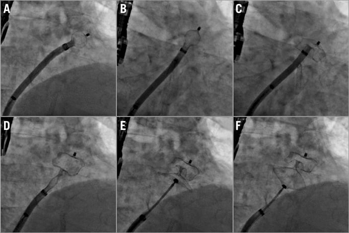
Figure 5. Device deployment steps. A) Ball position. B) Counterclockwise rotation. C) Deployment of device lobe. D) Deployment of device disc. E) Device stability evaluation before release. F) Gentle tug test.
Evaluation of LAAO, signs of device stability, tug test, and device release
Initial evaluation of the device position is carried out by TEE. The device is checked from multiple views and colour Doppler signals confirm the absence of peri-device leak and good coverage of the LAA ostium. Contrast medium injection also demonstrates successful LAAO. A profile projection without any overlay of lobe and disc is essential. There are five signs of device stability which need to be verified prior to release (Figure 5E). 1) The lobe of the device must be slightly compressed. 2) It should be oriented perpendicularly to the LAA walls at the level of the neck. 3) The disc of the device must have a concave shape. 4) It must be separated from the lobe. 5) The midpoint of the lobe should be distal to the left circumflex coronary artery where they are opposed. Most operators suggest performing a gentle but sustained tug test to verify device stability (Figure 5F). During this test, the device disc is pulled away from the lobe and held for 20-30 seconds and then relaxed back to the neutral position. It is essential that, following such a tug, the signs of stability are verified again prior to release. Occasionally, cardiac contractions may change the device position. Therefore, it is important to allow a few minutes for the device to settle in its final position before release. The screw should be detached while gently tugging on the pusher cable to avoid the detached screw getting caught up in the disc meshes. Haemostasis of the femoral vein may be achieved by manual compression, by figure of eight suturing or by using a vascular closure device (with preclosure).
How to recapture – change a device
In case the device is deployed in a suboptimal position or it relapses into the LA during the tug test, it needs to be recaptured. This is done by reversing the steps of deployment. Since the Amulet device has stabilising wires, it should not be retracted completely into the sheath (the radiopaque markers on the device should not enter the sheath on fluoroscopy), as the sheath tip may be damaged or invaginated. Invagination of the tip of the sheath is more clearly visible on cine X-ray than with fluoroscopy. If the device is completely retracted into the sheath and there is sheath invagination, its re-advancement may be impossible because of the invagination and the fact that the stabilising wires are pointing upwards rather than downwards. If this occurs, removal of the device and re-introduction of the sheath dilator over a J wire can reshape the tip of the sheath into its original form. In case the device is completely removed, the manufacturer recommends changing the delivery sheath prior to re-advancement of a new device. However, it is often possible to use the original device and sheath provided any tip invagination is corrected as described above. If a new device is used the re-used sheath has to be large enough for it. Re-using the sheath appears preferable, as exchanging the sheath carries an additional risk.
Additional safety measures
Two doses of antibiotics are typically given before and after the procedure, per institution protocol. If the procedure lasts >30 minutes the ACT should be re-checked and extra heparin should be administered as necessary to maintain the ACT within the target range of 250-300 seconds.
How to deal with chicken wing anatomy – the sandwich technique
According to the literature, chicken wing LAA anatomy is a common anatomic variation of the LAA35. The combination of chicken wing anatomy with an extreme bend and a short LAA neck requires a special closure technique called the sandwich technique (Figure 6)36. If the orifice of the wing is small (<6-7 mm) the device behaves as if this were a regular albeit short LAA, and closure should be carried out in a standard fashion.
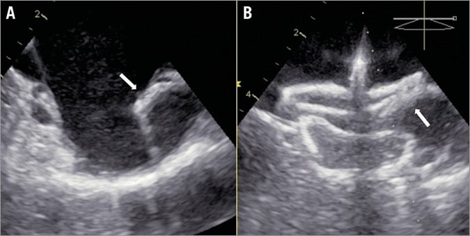
Figure 6. The sandwich technique for chicken wing anatomy. In case of chicken wing LAA anatomy with a severe bend, the device lobe is implanted parallel to the LAA wing, sandwiching the pulmonary vein ridge (white arrows) between the lobe and the disc (sandwich technique). LAA: left atrial appendage
The sandwich technique is indicated in case the neck (landing zone) of the chicken wing LAA is short (<15-20 mm). Its main characteristic is that the device lobe is not implanted in the standard neck position but rather the lobe lies along the length of the LAA body (wing), resulting in sandwiching the LAA ostium between the device lobe and disc. In this instance, sizing is also different, being dependent on the length of the LAA body or wing. Often, the standard fluoroscopic projections need to be modified in order to capture the true LAA configuration. In the majority of cases, a larger device is used. It should be noted that the >25 mm Amulet device lobe is longer than the ACP, which has to be taken into account in order to predict the feasibility of the sandwich technique and for proper sizing for a particular patient. Optimal TSP is crucial, because occasionally (e.g., in a reverse chicken wing where the wing points medially rather than laterally) the sheath needs to be positioned very deeply into the LAA (the use of a pigtail is recommended for such a manoeuvre). The sandwich technique is considered successful when four out of five signs of device stability exist. An exemption is the orientation of the device lobe, which is parallel to the LAA walls. It is important to confirm that no part of the device lobe is protruding into the LA, otherwise the risk of device embolisation is high. Sometimes, the sandwich technique can be challenging, especially when the LAA wing is pointing cranially. Deployment of the device lobe may require extreme counterclockwise rotation and several lobe recaptures. Of note, the Amulet lobe can be partially recaptured obtaining a flat, triangular shape. This can facilitate optimal orientation of the lobe in the LAA and proper engagement of its stabilising wires. Another useful trick is to pre-shape the delivery sheath manually in a configuration that will allow a better orientation. The sheath should be shaped with the dilator in place to avoid kinking. The sheath has the tendency to return to its default shape but part of the manually applied configuration remains (even a few degrees change may be crucial). The use of a hot air gun renders custom curve changes more durable.
Main differences between Amulet and ACP implantation technique
The main difference between the Amulet and the ACP in terms of implantation technique is the length of the device lobe (Figure 2). The Amulet lobe in sizes >25 mm has more volume so it needs more space for deployment. In addition, the Amulet waist is longer, so the device should be implanted slightly deeper as compared to the ACP. Nevertheless, these characteristics make the Amulet considerably more stable, so less oversizing is needed, especially for larger sizes. The addition of more and slightly more robust stabilising wires also increases stability. Another important difference is the ability for partial recapture of the Amulet lobe in a triangular atraumatic shape. Due to the recessed proximal female screw the Amulet can be snared only by the lobe tip, so extra caution is warranted to avoid embolisation. If migration of an Amulet device happens to a position where primarily the disc of the device is presented, it might be worthwhile trying to re-insert the delivery cable into the proximal female screw of the disc.
Conclusions
In conclusion, the introduction of the AMPLATZER Amulet device with its novel features aims to improve procedural success and patient safety in LAAO procedures. Procedural safety and long-term device efficacy are critical in a prophylactic procedure employed to avoid complications in an otherwise asymptomatic patient. Therefore, the safe application of a novel device iteration with improved device stability, appendage occlusion and procedural simplicity advances the broader application and attractiveness of this technology. Continuous evaluation of the device in clinical practice and pertinent scientific publications on LAAO are encouraged.
| Impact on daily practice Percutaneous left atrial appendage occlusion (LAAO) is a relatively new device-based therapy for stroke prevention in patients with atrial fibrillation. Due to the fragility and vast anatomical variability of the left atrial appendage, LAAO has been associated with a relatively high periprocedural major complication rate and is considered a technically demanding procedure. Following a pre-specified implantation protocol like the one herein described and being acquainted with a few tips and tricks coming from clinical experience may help in reducing the complications rate when performing LAAO and optimise the implant quality, with the AMPLATZER Amulet device in particular. |
Conflict of interest statement
A. Tzikas is a consultant and proctor for St. Jude Medical and has also received a research grant and speaker’s honoraria from St. Jude Medical. D. Meerkin is a consultant and proctor for St. Jude Medical. X. Freixa is a consultant and proctor for St. Jude Medical. I. Cruz-Gonzalez is a consultant and proctor for St. Jude Medical. T. Lewalter is a consultant for and has received speaker’s honoraria from St. Jude Medical. J. Saw is a proctor and consultant for St. Jude Medical and has also received research grants and speaker’s honoraria from St. Jude Medical and Boston Scientific. S. Berti is a consultant and proctor for St. Jude Medical. J. Nielsen-Kudsk is a consultant and proctor for St. Jude Medical. R. Ibrahim is a consultant and proctor for St. Jude Medical. D. Lakkireddy is a consultant for St. Jude Medical. V. Paul is a consultant and proctor for St. Jude Medical. D. Arzamendi is a consultant and proctor for St. Jude Medical. F. Nietlispach is a consultant and proctor for St. Jude Medical and has received speaker’s honoraria from St. Jude Medical. S. Worthley is a consultant and proctor for St. Jude Medical. D. Hildick-Smith is a member of the advisory boards and is a proctor for St. Jude Medical and Boston Scientific. J. Thambo is a consultant and a proctor for St. Jude Medical and Boston Scientific. C. Tondo is a consultant and proctor for St. Jude Medical. A. Aminian is a consultant and proctor for St. Jude Medical. Z. Kalarus is a consultant and proctor for St. Jude Medical. B. Schmidt is a consultant for St. Jude Medical and Boston Scientific. L. Sondergaard is a consultant and proctor for and has received research grants from St. Jude Medical. J. Kefer is a consultant and proctor for St. Jude Medical. B. Meier has received research grants to the institution and speaker’s honoraria from St. Jude Medical. J-W. Park is a consultant and proctor for and has received a research grant and speaker’s honoraria from St. Jude Medical. H. Sievert is a consultant for and has received a research grant and speaker’s honoraria from St. Jude Medical. H. Omran is a consultant and a proctor for and has received a research grant and speaker’s honoraria from St. Jude Medical. The other author has no conflicts of interest to declare.