Abstract
Aims: The optimal clinical protocol to detect fractures of transcatheter aortic valves is unknown. To the best of our knowledge, there are no published reports describing stent or frame fractures following transcatheter aortic valve implantation. The purpose of this study is two-fold: (1) to determine the optimal fluoroscopic protocol to identify potential fractures of the Medtronic CoreValve® frame; and (2) to implement this protocol in the analysis of the fluoroscopic films of patients implanted with the CoreValve® device with 1-year minimum follow-up.
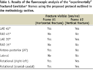
Methods and results: Considering the resolution of fluoroscopy (~ 0.2 mm), we used a 0.2 mm diamond-cutter to create a single fracture in a single strut of two CoreValve® frames. An intact CoreValve® prosthesis was used as control. These prostheses were subsequently implanted in post-mortem heart specimens. A protocol involving still frames and rotational (left-right and cranial-caudal) fluoroscopic imaging was then applied to the heart specimens. The experimentally induced fractures were detectable on the rotational cine runs (left-right and cranial-caudal); in some of the fixed acquisition sequences, however, the fractures were undetectable.
The fluoroscopic protocol was retrospectively applied to the films of 58 patients who underwent implantation with the CoreValve System® between October 2005 and August 2008 and had at least 1-year follow-up. The mean and median follow-up times were 22 months and 24 months, respectively (range 12 to 36 months). Rotational cine films (only left-right lateral) were available in 39 patients (60%). No frame fractures of the CoreValve® frame were identified.
Conclusions: Rotational cine runs in the left-right and cranial-caudal directions should be mandatory in the clinical assessment of the structural integrity of the CoreValve® frame. No frame fractures were identified in 58 patients implanted with the Medtronic CoreValve® device with 2-year mean follow-up.
Introduction
In order to design a durable and fatigue resistant transcatheter aortic valve, knowledge of the in vivo loading conditions is essential. The mechanical loading experienced by the device can be influenced by patient characteristics (e.g., blood pressure, compliance of the aortic root), sizing of the prosthesis (under- or over-sizing), deployed configuration (out-of-round), axial alignment, blood flow velocity and flow fields, and the biological response that occurs with time. Mechanical loading forces include those acting radially, in addition to torsional and bending forces. The relevant loading conditions must be considered or the durability and structural integrity of transcatheter aortic valves may be compromised. Although device manufacturers and regulatory agencies carefully assess anticipated durability, clinical experience provides the final confirmation of performance.
Femoral-popliteal stent fractures have been reported in 8-37% of patients1-3. Furthermore, fractures have been identified in 10-30% of patients following pulmonary artery stenting or transcatheter pulmonary valve implantation4-7. In fact, the frequency of fractures can vary with the site of implantation (i.e., body location) and duration of implant – both related to the variability in loading conditions. Stent fractures may or may not be associated with clinical implications. To the best of our knowledge, there are no published reports of stent or frame fractures following transcatheter aortic valve implantation.
The purpose of this study was two-fold: (1) to determine the optimal fluoroscopic protocol to identify potential fractures of the Medtronic CoreValve® frame (Medtronic, Minneapolis, MN, USA) and (2) to implement this protocol in the analysis of the fluoroscopic films of patients implanted with the CoreValve® device with 1-year minimum follow-up.
Methodology
PART I. Experimentally-induced fracture of the CoreValve® frame and its assessment using fluoroscopy
PROTOCOL DESIGN OVERVIEW
For the purpose of this study we used two CoreValve® prostheses with experimentally induced fractures (as will be described below) and one CoreValve® prothesis as control. The three prostheses were examined under fluoroscopy; initially bare (Figure 1A) and after orthotopic implantation in a post-mortem human heart (Figure 1B).
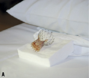
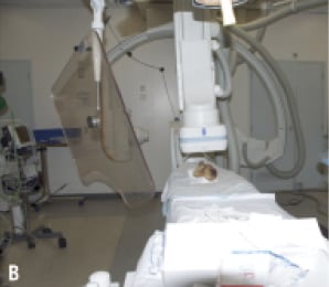
Figure 1. A. Fluoroscopic imaging of “bare” CoreValve® prosthesis. B. Fluoroscopic imaging of CoreValve® prosthesis after orthotopic implantation into post-mortem heart.
Thus, six sets of examinations were performed. For each set, we performed the following image acquisition sequence:
1. RAO 45º and LAO 45º
2. RAO 35º and LAO 35º
3. AP
4. 90º left lateral
5. Rotational (left-right)
6. Rotational (cranial-caudal)
The fluoroscopic frame rate was set at 30 frames/second. Furthermore, the images were acquired with the greatest magnification factor and saved with the option of additional post-processing magnification. The data were archived with a spatial resolution of 1024 x 1024 pixels for highest image quality.
THE DEVICE
The CoreValve® bioprosthetic heart valve consists of a nitinol frame and was designed with three distinct regions (Figure 2).
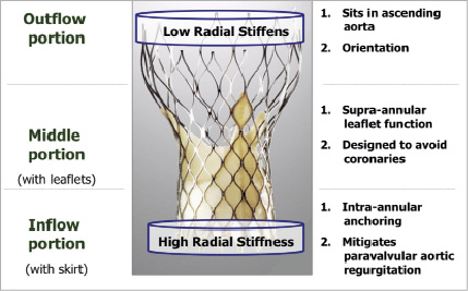
Figure 2. The inflow portion has high radial stiffness and functions to anchor the valve against the left ventricular outflow tract and native aortic valve leaflets. The middle portion, where the prosthetic leaflets reside, is waisted to resist deformation and maintain leaflet geometry and maintain coronary perfusion. The outflow portion, which sits in the ascending aorta, has low radial stiffness and orients the prosthesis axial to the aortic root.
The inflow portion has high radial stiffness and functions to anchor the valve against the left ventricular outflow tract and native aortic valve leaflets. The middle portion, where the prosthetic leaflets reside, is waisted to resist deformation and maintain leaflet geometry and maintain coronary perfusion. The outflow portion, which sits in the ascending aorta, has low radial stiffness and orients the prosthesis axial to the aortic root.
DEFINITIONS
A fracture was defined as a discontinuity in the appearance of a strut of the CoreValve® frame. A strut is bordered at its two ends by nodes (Figure 3).
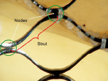
Figure 3.The red parenthesis represents a strut of the frame. The strut is bordered at its ends by nodes (green circle).
There are nine nodes and 10 struts across the total frame of the CoreValve® bioprosthesis (Figure 4).
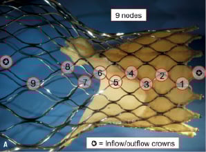
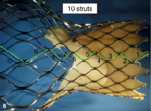
Figure 4 A. There are a total of nine nodes across the length of the frame. Either end of the frame consists of a half diamond – known as the inflow and outflow crown B. There are a total of 10 struts across the length of the frame.
Based on their location within the tri-level frame design, struts were further classified as follows: struts 1-3 as inflow struts, 4-8 as commissural struts, and 9-10 as outflow struts. In addition to being useful to communicate fracture location, this classification can be used to discuss potential clinical and/or functional implications of strut fractures.
The CoreValve® frame is constructed using a diamond shape motif (i.e., repeating diamond cell configuration). A diamond cell consists of four struts (Figure 3). There are a total of five full diamonds across the length of the CoreValve® frame.
EXPERIMENTALLY INDUCED FRACTURE
Considering the resolution of fluoroscopy (~ 0.2 mm), we used a 0.2 mm diamond-cutter to create a single fracture in the inflow strut of two CoreValve® frames; in one prosthesis the fracture was created horizontal and in the second prosthesis it was vertical with respect to the long axis of the frame (Figure 5).
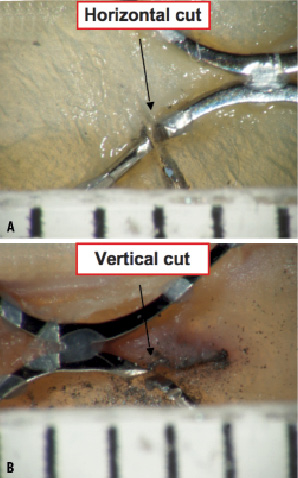
Figure 5. Microscopic evaluation (15X) of the frame with the horizontal cut (A) and the frame with the vertical cut (B). In both cases, the cut measured approximately 0.3 mm.
We hypothesised that the orientation of the fracture plane will have an impact on the visibility of the fracture depending on the gantry-viewing angle (Figure 6). This was another reason why we performed rotational fluoroscopy in both the left-right and cranial-caudal directions.
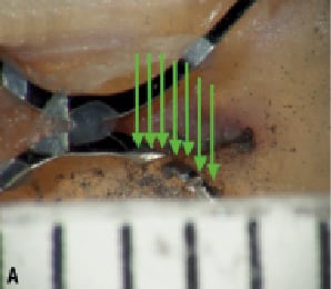
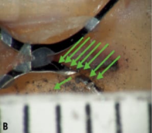
Figure 6. A. The x-rays (green arrows) in this orientation cannot pass through the cut and therefore would not be detected. B. A change in gantry position allows x-rays to pass through the cut and be detected.
MACRO- AND MICROSCOPIC INSPECTION OF THE FRAMES
The induced fractures were barely noticeable on gross inspection (Figure 7). Microscopic analysis confirmed the orientation of the fractures in the vertical and horizontal planes (Figure 6). Furthermore, both fractures measured approximately 0.3 mm in width.
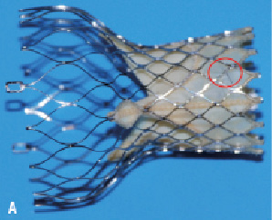
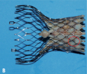
Figure 7. Experimentally-induced fractures (seen microscopically in Figures 5 and 6) are hardly visible by macroscopic inspection.
FLUOROSCOPIC FRAME ANALYSIS
The goal of the fluoroscopic frame analysis was to systematically evaluate each visible strut in each of the acquired projections. In order to do this, we highlighted each frame strut (after being analysed) using the measurement “length” tool of 5.4 CASS QCA software (Pie Medical Imaging BV, Maastricht, The Netherlands). Overlapping struts were not analysed as was assumed that alternative projections would allow us to fully evaluate the entire frame. If there was a suspicion of a fracture, the region of interest was further magnified and re-analysed. Table 1 describes whether the fracture was visible based on several viewing angles pre-defined in the study.
PART II. Clinical evaluation protocol
PATIENTS
Cardialysis Core Lab reviewed the fluoroscopic films of 58 patients who underwent implantation with the 3rd generation CoreValve System® between October 2005 and August 2008 and had 1-year minimum follow-up. Of these 58 patients, 27 and 31 patients were enrolled in the 18 Fr safety and efficacy study and 18 Fr post-marketing expanded evaluation registry, respectively. The fluoroscopic films were obtained retrospectively.
After receiving thorough training about the CoreValve System® and the frame fracture assessment protocol, two independent analysts reviewed each patient file. A fracture was defined as a discontinuity in the appearance of a strut of the CoreValve® frame. A certified cardiologist supervised the analysis.
Results
The mean and median follow-up times were 22 months and 24 months, respectively (range 12 to 36 months). Subjective image quality was graded as “good” in 31 assessments, “fair” in 30, and “poor “in two. All films were stored and analysed with a resolution of 512 x 512 pixels. The recorded frame rate ranged from 10 to 30 frames/sec (10 frames/sec n = 11 assessments, 12.5 frames/sec n = 9 assessments, 15 frames/sec n = 24 assessments, 25 frames/sec n = 2 assessments, 30 frames/sec n = 16 assessments, not available n =1 assessment). The number of still images per assessment available for analysis ranged from 1 to 15 (Figure 8). In addition to the still images, rotational films (only left-right lateral) were available in 39 patients (60%).
No frame fractures of the CoreValve® frame were identified in the 58 patients.
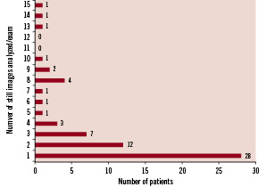
Figure 8. The majority of patients (n=40) had one or two still images available for analysis.
Discussion
This manuscript deals with the relevant issue of the long-term performance of transcatheter aortic valves. This is the first work to present the complex issue of analysing the structural integrity of transcatheter aortic valves. The experimental protocol study allowed us to make several important observations about frame fracture analysis of the CoreValve System®. First, rotational cine runs in the left-right and cranial-caudal directions are mandatory. Experimentally induced fractures were apparent in each of the rotational cine runs; in some of the fixed acquisition sequences, however, fractures were not apparent. In addition to the orientation of the fracture plane, the orientation of the valve within the body and the circumferential location of the fracture can influence the viewing angle needed to appreciate the fracture. Furthermore, overlapping struts may eclipse an otherwise visible fracture. In these cases, slight adjustments of the viewing angle may be sufficient enough to relieve the overlap and detect the fracture. Second, systematic analysis of the frame should be performed on a per strut basis using a highlighting technique as described in our methodology. This will ensure complete inspection of the prosthesis.
A major limitation of the in vitro study relates to the impossibility to mimic the physical characteristics of potential frame fractures in vivo. Keeping in mind the resolution of fluoroscopy (0.2 mm), we purposely induced a strut separation of 0.3 mm using a diamond cutter. It is plausible that forces inducing a fracture would also separate the two rims of the fractured strut and lead to easier detection. In addition, a radiological approach in post-mortem hearts has obvious limitations including x-ray penetration, presence/absence of calcification, and beating heart movements. Nevertheless, this study points to the possible difficulties associated with frame fracture analysis of transcatheter aortic valve prostheses.
In the clinical component of this study, we did not identify any fractures of the CoreValve® frame in the fluoroscopic films of 58 patients with one to three year follow-up. A limitation of this clinical study lies in the retrospective collection of films. Although the image quality of the films was acceptable, a number of items need highlighting. First, the resolution of the images was 512 x 512 pixels and not the recommended 1024 x 1024 pixels. Second, only one-quarter of films analysed had the recommended frame rate of 30 frames/sec. Third, rotational films (left-right), which safeguard against strut overlap, were available in approximately two-thirds of films. No patient had both left-right and cranial-caudal rotational examinations.
The potential difficulty to identify frame fractures on fluoroscopy, coupled to their unknown clinical implications, can result in clinically silent frame fractures. Albeit so, and to the best of our knowledge, there have been no published reports of a CoreValve® frame fracture after more than 6,000 implantations worldwide. This is in contrast to the clinical experience with transcatheter pulmonary valve implantation where stent fractures are reported to occur in approximately 20% of patients, the majority being incidental findings5,7.
What are the clinical or functional implications of a CoreValve® frame fracture? The answer would be speculative at best and in part, may be related to the site of fracture. A fracture involving the inflow struts would likely have no implications on valve function or durability (Figure 9).
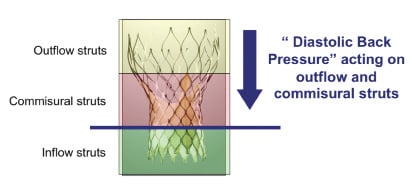
Figure 9. The cyclic diastolic pressure load is imparted on the commissural and outflow struts. It is possible that a commissural strut fracture would have greater implications for valve function and durability than an inflow strut fracture.
On the other hand, a fracture involving the commissural or outflow struts may have an impact on valve function and/or durability as these struts are linked to the prosthetic valve leaflets and absorb the “back pressure” during diastole. Finite element analysis can be used to identify peak strain locations on the frame based on the loading conditions entered into the model.
Nitinol as a “smart” material
Nitinol is a soft martensite material with a composition of approximately 50% nickel and 50% titanium. Nitinol is more radiopaque than stainless steel. Its shape memory characteristics are attributed to a reversible crystalline phase change known as martensitic transformation8. The reversible phase transformation can be thermal dependent or stress-induced (i.e., mechanical). In either event, nitinol always attempts to revert back to its original austenite form. The fact that nitinol can tolerate mechanical strains of up to 10% and recover its original shape lends itself to compact designs and small delivery systems9.
Prior to valve loading, the CoreValve® frame is expanded and assumes its austenitic shape. The CoreValve® frame is cooled down and mechanically crimped into a smaller diameter (martensitic) and loaded into the sheathed delivery system. During valve deployment, the frame is exposed to body temperatures and attempts to self-expand back to its austenitic shape. The CoreValve® frame, however, undergoes restrained recovery; surrounding structures prevent the material to fully recover to its original austenitic shape. Although this kind of recovery allows the CoreValve® frame to anchor itself within the aortic root, it also means that the frame is subjected to a mean loading effect. The mean loading effect, in addition to the cyclic pressure changes can contribute to frame fatigue.
Frame fatigue can be influenced by patient characteristics (blood pressure, aortic compliance), sizing of the prosthesis (under- or over-sizing), deployed configuration (out-of-round), axial alignment, blood flow velocity and flow fields, and the biological response over time. Mechanical loading forces include those acting radially, in addition to torsional and bending forces. Changes in mechanical loading forces associated with the biological response over time requires further study as this may influence frame fatigue. A better understanding of the in vivo loading conditions can lead to more accurate in vitro frame fatigue testing, improved valve designs, and ultimately increase patient safety.
In summary, the purpose of this study was to develop a method for acquiring and analysing fluoroscopic images of the CoreValve® device for frame fractures. Secondly, we did not identify any fractures of the CoreValve® frame in the fluoroscopic examinations of 58 patients with one to three year follow-up (mean 2 year follow-up). The lessons learned in this study and the proposed protocol (see appendix) should be applicable to most radiopaque transcatheter aortic valves.
Appendix
Guidelines for acquisition of fluoroscopic images intended for frame fracture analysis of transcatheter aortic valves (Cardialysis)
To improve the accuracy and reproducibility of frame fracture analysis, the following guidelines are proposed:
– Use a fixed table system and biplane x-ray equipment, if available.
– Recommended resolution: 1024 x 1024 pixels.
– All cine runs should be ECG-gated and be recorded with 30 frames/second.
– A single cine run should have duration of at least 10 heartbeats.
– The maximum magnification factor should be applied during fluoroscopy with the option of additional post-processing magnification
– For still images, the following views are required:
- Antero-posterior (AP)
- Lateral (LAO 90°)
- 2 additional orthogonal views (with minimal overlap of frame struts)
- Repeat the gantry views that were obtained during the index procedure immediately after valve implantation and at any follow-up study
– For rotational images, the following views are mandatory:
- Lateral: left to right (90 to 90 degrees lateral)
- AP: cranial to caudal (as far cranial and as far caudal)
– The frame should preferably be located near the centre of the screen/image in order to be entirely visible.
– There should be no overlap of the frame with other catheters or electrodes.
– Foreshortening of the frame should be avoided.