In this chapter of Tools & Techniques, percutaneous catheter-based left ventricular support using the Impella CP is discussed using a stepwise approach. The following is a summarised overview of the chapter. The complete, unabridged version with images is available online at: http://www.pcronline.com/eurointervention/81st/206.
Background and indications
The Impella CP (Abiomed Europe GmbH, Aachen, Germany) is a catheter-mounted axial-flow pump, which provides active unloading of the left ventricle. The Impella device has demonstrated efficacy in patients ranging from those with acute coronary syndromes to those with acute cardiogenic shock. Additionally, it is widely used as circulatory support in high-risk percutaneous coronary interventions.
Although the Impella CP device is similar in design to the Impella 2.5 device, key differences and technique will be discussed in this article. In addition, we will try to give more insight into technical specifications and try to provide some tips and tricks for the users.
Insertion and placement
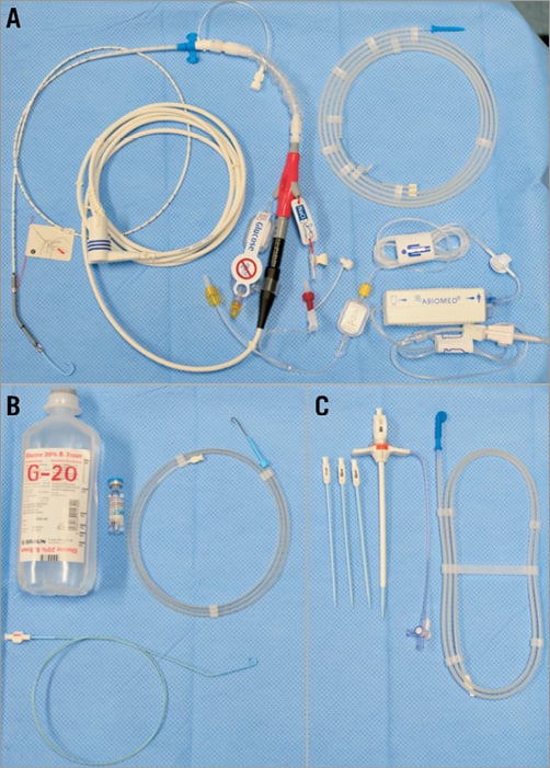
The Impella CP comes with almost all the materials needed (Figure 1). To begin a case, the Automated Impella® Controller (AIC) (Abiomed) is turned on and a series of prompts allows the user to connect the purge line to the pump. Upon completion of these set-up steps, the Impella catheter is ready for implantation. The 14 Fr peel-away introducer sheath is inserted after obtaining arterial access to the femoral artery and predilation of the vessel. Activated clotting time (ACT) should be maintained above 250 seconds during Impella implantation.

Figure 1. This figure shows all the items that come with the pump in the same package. A) Impella CP catheter pump, electrical extension cable, purge cassette and 0.018” super stiff silicone/PTFE-coated guidewire for pump placement. B) The accessories needed and which are typically available in an interventional lab to perform a case are shown (4 Fr pigtail preferably without side holes, standard 0.035” J-wire, 20% glucose solution [500 ml], unfractionated heparin [25,000 IE]). C) Impella CP 14 Fr introducer kit.
A pigtail catheter is then advanced over a 0.035” J-wire into the left ventricle and placed optimally into the apex. The diagnostic guidewire is removed and a 0.018” stiff placement guidewire is inserted and placed into the apex after forming a curve at the end of the wire. The end of the 0.018” guidewire is fed through the pigtail of the Impella CP catheter. A pre-inserted red lumen serves as a loading aid for the guidewire to ensure it exits through the desired window.
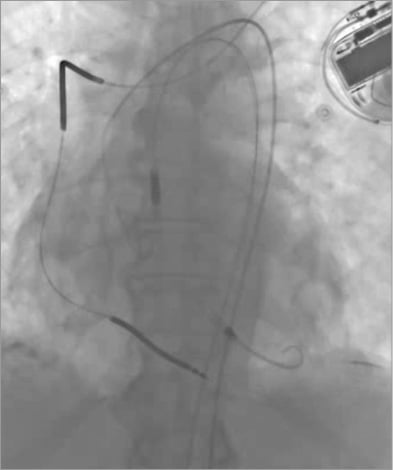
Once the Impella CP catheter is loaded onto the guidewire, it is then inserted under fluoroscopy into the femoral artery through the introducer sheath and advanced along the placement guidewire across the aortic valve. The Impella CP is positioned with the inlet in the middle of the left ventricle below the aortic valve annulus and the outlet in the ascending aorta. The placement wire is then removed and position is confirmed with fluoroscopy before starting the Impella CP (Figure 2). After verifying optimal pump position, return to previous or desired flow rates. Post implantation, ACT should be maintained at 160 to 180 seconds.

Figure 2. Fluoroscopic image of an Impella CP pump placed in the left ventricle.
If the patient is being transferred to the intensive care unit while on Impella support, the 14 Fr peel-away introducer has to be removed. It is recommended to note the transversal mark at the catheter shaft for reference of proper pump position. Lastly, the purge set-up configuration has to be set to standard mode. The user needs to follow the instructions for setting up a sodium chloride (0.9% NaCl) infusion for the pressure sidearm. During Impella explant, the pump performance level should be reduced to P2 until the pump is pulled back into the aorta and then reduced again to P0 before pulling the pump out completely.
Impella console display and pump characteristic curves
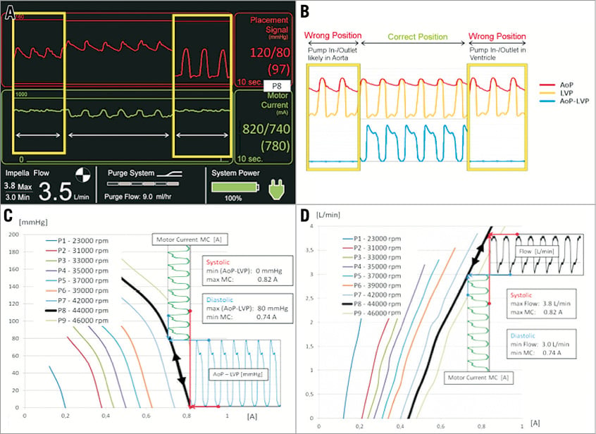
Hydraulic performance of the Impella CP pump (Figure 3A) is dependent on the delta pressure between pump inlet and outlet. When the device is correctly positioned across the aortic valve this delta pressure is equal to the pressure difference between aortic pressure (AoP) and left ventricular pressure (LVP). At a given rotational speed (P1-P9/23k RPM-46k RPM) the motor current follows a set of characteristic curves (Figure 3B, Figure 3C) that are determined by the delta pressure and the rotational speed of the impeller.

Figure 3. Hydraulic characteristics of an Impella CP and basic principles of flow calculation and position monitoring. A) Impella console display. B) AoP and LVP for wrong and correct position. C) Motor current to (AoP-LVP) relation at different rpms. D) Flow calculation based on motor current.
The Impella CP is capable of delivering maximum flows up to 4.1 L/min at performance level P9. The motor current maximum is reached during systole and the minimum is reached during diastole. High motor currents are associated with higher flows and higher pump speeds and, as such, pump flow is the highest during systole and lowest during diastole.
The placement signal shown on the console display is a close approximation of the central aortic pressure if the pump is correctly positioned. Algorithms within the console combine the data on placement signal, motor current and rotational speed to obtain information on the positioning of the pump relative to the aortic valve. A non-pulsatile motor current waveform (Figure 3D) is a strong indicator of incorrect pump position. With the inlet and outlet in the same cavity the delta pressure will drop to zero and the pump flow will be close to its maximum value for the given rotational speed with a flat motor current line.
We refer to the online version of the manuscript for a detailed technique and device description. In our experience the Impella CP implantation is safe, fast and uneventful if performed in the standard manner described in this manuscript.
Conflict of interest statement
C. Nix is a full-time employee of Abiomed Europe GmbH. The other authors have no conflicts of interest to declare.

