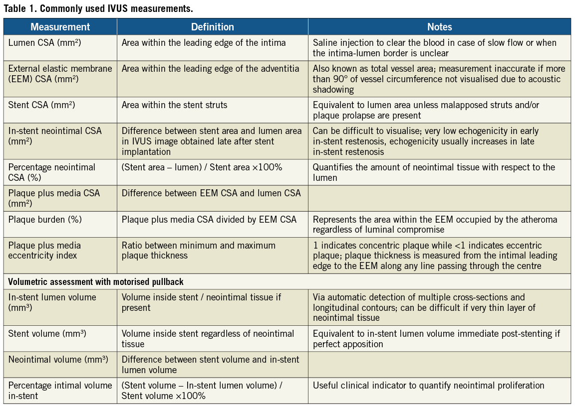
Abbreviations
CSA / MLCSA: cross-sectional area / minimal lumen CSA
CTO: chronic total occlusion
DES: drug-eluting stent
FFR: fractional flow reserve
IEL: internal elastic lamina
ISA: incomplete stent apposition
IVUS: intravascular ultrasound
LM: left main
MLA: minimal lumen area
OCT: optical coherence tomography
SB: side branch
Introduction
In this chapter of Tools & Techniques, intracoronary imaging is discussed using a stepwise approach. The following is an summarised overview of its application in the cathlab. The complete, unabridged version with images is available online at www.eurointervention.org. Coronary angiography had traditionally been used in our cardiac catheterisation laboratories in assessing the severity of coronary lesions, sizing the vessels and guiding the implantation of coronary stents. Both intracoronary imaging techniques, IVUS and OCT, provide additional information able to improve guidance of interventional procedures and are indispensable to carry out clinical research.
Intravascular ultrasound (IVUS)
Two major existing IVUS systems include 1) the mechanical system, based on a single rotating transducer and 2) the electronic, or “solid-state” system. Typical resolution of a 20 to 40 MHz IVUS catheter is 80-100 microns axially and 200 to 250 microns laterally. Utilising the automatic pullback in selected IVUS systems, with speeds set at between 0.5 and 2 mm per second, length of vessel and location of lesions could be more accurately identified.
In general, mechanical systems can provide higher resolution because of the higher ultrasound frequency, usually 40-45 MHz. However, these catheters are compatible with a 6 Fr or above guide catheter only. Commercially available mechanical systems include the Revolution 45 MHz catheter (Volcano Corp., Rancho Cordova, CA, USA), iCross / Atlantis SR Pro2 40 MHz catheter (Boston Scientific, Santa Clara, CA, USA), LipiScan 40 MHz catheter (InfraReDx, Burlington, MA, USA), Intrafocus WR 40 MHz catheter and the ViewIT catheter IVUS (Terumo Corp., Tokyo, Japan). The only electronic or solid-state system currently in use is the Eagle Eye Gold catheter (Volcano Corp., Rancho Cordova, CA, USA) which provides IVUS images at 20 MHz and is compatible with a 5 Fr system thus often used in IVUS-guided re-entry in CTO.
Clinical applications
Based on the current clinical practice, IVUS is indicated to evaluate a coronary lesion when angiographic assessment is inconclusive, to optimise stent implantation, particularly in heavily calcified vessels for guidance of rotational atherectomy prior to stenting and more frequently, in guidance of LM interventions. (Figure 1)
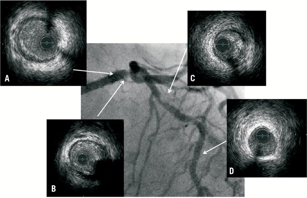
Figure 1. Distal LM lesion with suboptimal angiographic views. IVUS provides information on the anatomical severity of lesions and on how to guide stent implantation. A) Proximal LM with lumen CSA of 13.2 mm2; B) Distal LM lesion with lumen CSA of 5.8 mm2; C) Proximal LAD lesion with lumen CSA of 3.2 mm2; D) Healthy vessel at mid LAD with lumen CSA of 6.7 mm2. Patient subsequently underwent stenting to LM into LAD with XIENCE PRIME (Abbott Vascular, Santa Clara, CA, USA) 3.5×38 mm with post-dilatation at LM using a 4.0 non-compliant balloon.
Assessment of the intermediate lesion
A MLA <4.0 mm2 on IVUS has good correlation with FFR <0.751 but this should not be used as the sole criteria to justify revascularisation as Koo et al recently suggested different cutoff values should be used depending on anatomical location of lesions and size of vessels.
Guidance of left main intervention
A MLA cutoff valve of 6.0 mm² is the most widely employed cutoff value to determine whether or not an intermediate LM lesion warrants revascularisation, but recently Park et al suggested a lower cutoff of 4.8 mm², which correlates well with a FFR <0.8².
Guidance of stent optimisation
Incomplete stent expansion and strut malapposition lead to higher incidence of subacute stent thrombosis and restenosis. Studies comparing angiographic-guided versus IVUS-guided PCI using different IVUS criteria include MUSIC, OPTICUS, AVID and AVIO3-6. Despite leading to larger stent dimensions, IVUS-guided strategy did not demonstrate improved clinical outcomes in these studies.
Restenosis and stent thrombosis
By utilising IVUS, factors commonly associated with restenosis and/or stent thrombosis including stent under-expansion, incomplete stent apposition (ISA), incomplete lesion coverage, geographic miss, plaque protrusion and small intraluminal thrombus can be detected. IVUS studies confirmed that the most common mechanism of restenosis after DES is stent under-expansion7-9 and IVUS-guided PCI in DES has also demonstrated reduced rates of stent thrombosis when compared with angiography-guided PCI10.
IVUS-guided CTO intervention (Figure 2)
When the guidewire goes into the subintimal space, a small calibre IVUS catheter such as the Volcano Eagle Eye can be advanced into the subintimal space to visualise the distal true lumen which is the target for re-entry with a stiff CTO guidewire. The same principle can also be employed in the retrograde recanalisation of a CTO11.
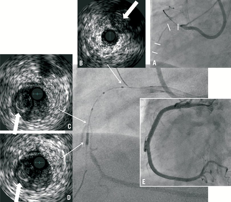
Figure 2. A) Angiogram showing double occlusions in RCA, proximal and mid segments (indicated by white lines); B) IVUS performed with Eagle Eye Gold catheter (Volcano, USA) from conus branch showing CTO stump (indicated by arrow) at proximal RCA; C-D) Confianza Pro 12 guidewire entered into subintimal space from proximal to mid RCA and entered a side branch distal but in close proximity to the occlusion with IVUS performed. White arrow indicates CTO with IVUS catheter in subintimal space; E) Final angiographic result after stenting with Resolute Integrity 3.5×38 mm and 3.5×24 mm stents.
Methods / techniques
Image acquisition
Before imaging
1. Insert the motorised pullback system into a sterile plastic bag
2. Connect the IVUS imaging catheter to the built-in interface of the pullback system or directly to the imaging console (for the Volcano Eagle Eye Gold catheter)
3. Enter patient demographics and vessel examined into the IVUS console
4. Flush the IVUS catheter with normal saline in a small 2.0 ml syringe with Luer-lock connecting to the IVUS imaging catheter (for the mechanical system)
5. Select the pullback speed to 0.5 mm/s (recommended)
6. Activate the system and confirm that a proper image is seen before insertion into the guiding catheter
7. Administer 0.1-0.3 mg of intracoronary nitroglycerine or 1-3 mg of Isosorbide Mononitrate according to blood pressure to reduce coronary spasms
During imaging
1. Before intracoronary insertion, disengage the guiding catheter in order to image up to the coronary ostium and the aorto-ostial junction. For electronic catheters, subtract the ring-down artefact while blood is present around the catheter (at the ostium)
2. Advance the catheter distal to the segment of interest
3. Optimise the ultrasound setting (depth and gain) according to the vessel size
4. Start digital acquisition / mechanical pullback
5. Monitor ECG and arterial pressure during pullback to rule out prolonged ischaemia, especially during pre-dilatation pullbacks
6. Complete the pullback, in general, wait until the catheter arrives at the coronary ostium or is withdrawn inside the guiding catheter
7. Avoid interrupting the mechanical pullback to examine specific segments of interest but rather recall the cross-sections of interest from the digital archives
8. Re-insert the IVUS catheter for image acquisition in a segment of interest only if the result is doubtful in interpreting the image
After imaging
1. Flush the IVUS catheter with the same 2.0 ml Luer-lock syringe (in particular for mechanical catheters) and wipe it with a wet gauze
2. Advance the catheter on the motorised pullback system ready for the next pullback
3. Replay the whole IVUS run, identify structures of interest and perform measurements (diameters and areas) of the most important cross-sections (usually proximal and distal reference, minimal cross-sectional area within the lesion or minimal cross-sectional stent area or other segments of interest)
4. Allow longitudinal display of the image after longitudinal reconstruction and measure the length of the segment of interest to guide device length selection
Image measurements
Both the ESC and ACC have provided us with guidelines regarding the nomenclature and interpretation of IVUS images12,13. Important and commonly used measurements are shown in Table 1. By averaging the proximal and distal reference vessel diameter/area, a good estimation of the lesion severity can be provided. Longitudinal measurement is also possible with the motorised pullback which can guide us to choose the optimal size and length of balloons/stents.
Optical coherence tomography (OCT)
As compared to IVUS, OCT has a resolution 10 times higher (10–15 µm vs. 100 µm) while IVUS can provide image through blood and deeper through the tissue (2 mm vs. 1 cm). Currently the only commercially available C7-XR OCT system (St Jude Medical LightLab, St. Paul, MN, USA) consists of the C7 Dragonfly™ imaging catheter compatible with a 6 Fr guide which can generate pullback at up to 25 mm/s covering 54 mm within a single pullback.
Clinical applications
The value of OCT is the superior ability to study apposition and neointimal coverage after stent implantation. However, its poor penetration makes it less favourable in guiding coronary intervention. Usual indications for OCT include:
Assessment of lesion severity
OCT can be an appealing alternative to FFR and IVUS in terms of determining the functional significance of lesions. However, there are no studies so far comparing FFR and OCT MLCSA.
Use in acute coronary syndromes (Figure 3)
Thin-cap fibroatheroma (TCFA), plaque rupture and intracoronary thrombus are frequently observed in acute coronary syndromes. OCT is more sensitive compared to IVUS and thus able to identify the underlying pathophysiological mechanism in ACS14-16.
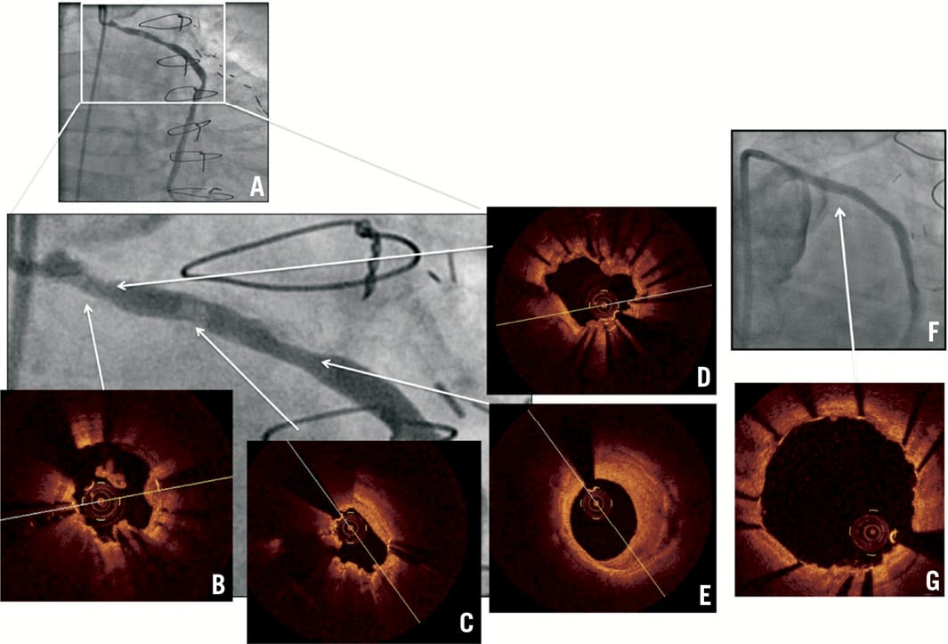
Figure 3. Patient with previous CABG and PCI presenting with unstable angina with ECG showing ST depression in V5-V6. A) Angiogram showing previously implanted TAXUS stent in the SVG-OM with focal stenoses and filling defects; B) OCT: multiple thrombi; C) Thrombus; D) In-stent restenosis with thrombus; E) Thick fibrous plaque; F) Angiogram after implantation of 3.5×15 mm over-and-under pericardium-covered stent; G) OCT: stent struts well-apposed without intraluminal thrombus.
Guidance of coronary interventions
OCT assessment is often based on the lumen diameter rather than on the vessel diameter/area as in IVUS. Two studies have demonstrated the feasibility of OCT in guiding coronary intervention17,18.
Bifurcation interventions (Figure 4)
In the strategy to open the stent strut at the SB ostium, distal cell re-crossing followed by subsequent kissing balloon inflation provides optimal apposition at the bifurcation. By performing OCT pullback after SB re-crossing, the location of SB guidewire can be easily tracked19.
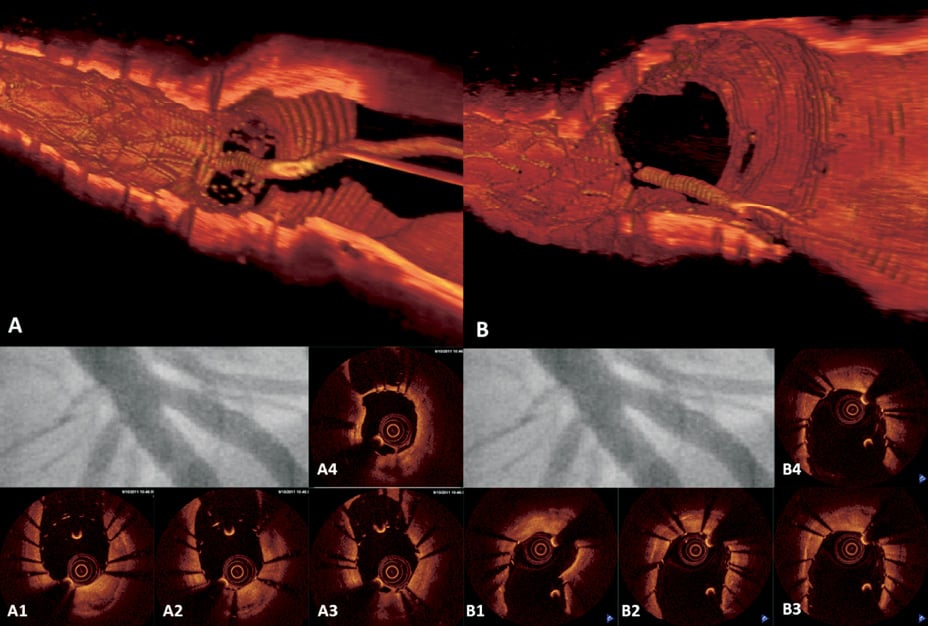
Figure 4. LAD & D1 bifurcation stenting using Culotte technique. No difference angiographically before and after kissing balloon inflation but OCT provides information on optimal position for re-crossing and strut apposition at bifurcation. A) OCT 3D reconstruction: view from LAD, stent struts at D1 ostium prior to kissing balloon inflation; A1 to A4) OCT pullback in LAD: guidewire re-crossing of D1 ostium at distal cell; B) OCT 3D reconstruction: view from LAD, stent struts at D1 ostium after kissing balloon inflation, complete apposition; B1-B4) OCT pullback in LAD: no floating or unapposed struts at D1 ostium.
Stent apposition and healing
Owing to its high resolution, OCT is the best intracoronary technique to evaluate stent strut apposition and neointimal coverage. This is particularly important in the second generation DES when the average late lumen loss is as low as 0.1-0.2 mm where OCT offers an excellent evaluation of the neointimal coverage.
Techniques
Image acquisition
Before imaging
1. Insert the imaging adaptor into a sterile plastic bag.
2. Connect of the OCT imaging catheter with the imaging console.
3. Enter the patient demographics and the vessels examined.
4. Flush with undiluted contrast in a small 2.0 ml syringe with a Luer-lock connecting to the OCT imaging catheter.
5. Automatic calibration starts once the OCT catheter is connected to the imaging console. A flashing red light should be seen at the tip of the OCT imaging catheter, otherwise check the connection.
6. Connect the power injector to the guiding catheter for contrast injection. Check meticulously to avoid air embolism. Alternatively, use the automated contrast injection system if available in the cardiac catheterisation laboratory.
7. Set the pullback speed at 20 mm/s. This would allow assessment of length of vessel segment between 30-50 mm with approximately 15-20 ml of contrast. If detail assessment e.g., bifurcation lesions, or improved resolution for 3D reconstruction is needed, pullback speed could be lowered.
8. Set the contrast infusion rate at 3-5 ml/s for left coronary system and 2-4 ml/s for right coronary artery, modified according to the vessel size and run-off.
During imaging
1. Advance the catheter distal to the segment of interest and position according to the vessel segment of interest.
2. Start scanning by activation from the image console (flushing the OCT catheter at this moment might damage the catheter which should be avoided).
3. Start contrast injection.
4. Start OCT pullback when an optimal blood clearance is achieved as seen on the monitor of the image console.
5. Acquire the fluoroscopic images simultaneously.
6. Monitor ECG, heart rate and arterial pressure during pullback to rule out ischaemia.
7. Withdraw the OCT imaging catheter into the guiding catheter once the pullback is completed.
8. Re-insert the OCT catheter for image acquisition in another segment of interest if needed.
After imaging
1. Flush the OCT catheter with the same 2.0 ml Luer-lock syringe with undiluted contrast and wipe it with wet gauze to remove the blood.
2. Replay the whole OCT run, identification of the endoluminal border and measurement of vessel diameters/area are automatically performed by the imaging system.
3. Adjust the auto-detected endoluminal border if necessary, usually when blood clearance is sub-optimal or at bifurcation. Minimum and maximum diameters are automatically measured.
4. Allow longitudinal display of the image after longitudinal reconstruction and measure the length of the segment of interest to guide coronary intervention.
5. OCT analysis was performed on-line using the C7 system and off-line using a dedicated review workstation.
IMAGE MEASUREMENTS
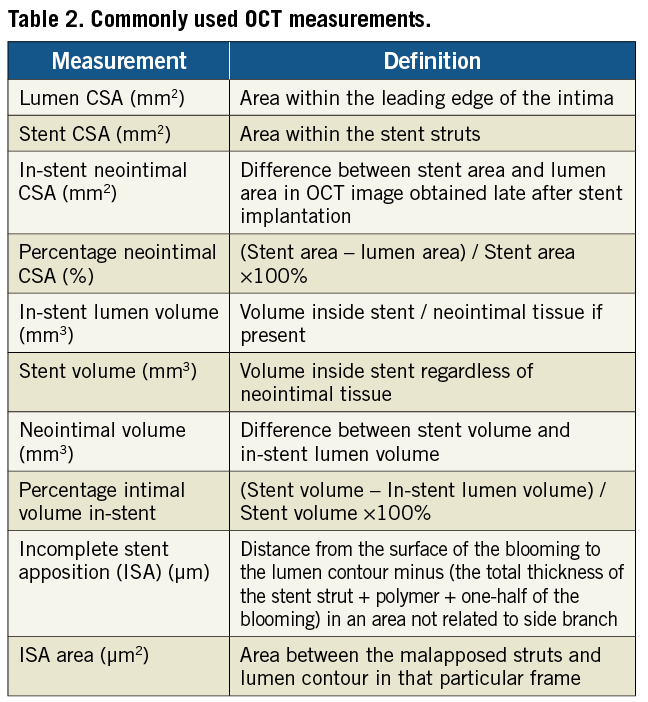
Normal coronary artery and different plaque morphologies have been well-defined on OCT and a consensus document was published in 201020. Important and commonly used measurements are shown in Table 2.
To obtain accurate measurements, the OCT image has to be calibrated by adjusting the z-offset, which is the zero-point setting of the system, prior to offline analysis and monitored throughout the longitudinal segment. Plaque is defined as the area between the endoluminal border of the intima and the media delimited by the IEL, which represents the true histological area of the plaque as opposed to IVUS which measures plaque plus media.
Apposition, defined as the contact of the stent struts with the vessel wall, can be assessed by measuring the distance between the abluminal reflection of the strut and the vessel wall, and comparing this distance with the strut thickness.
Conflict of interest statement
The authors have no conflicts of interest to declare.