Abstract
Left main (LM) coronary bifurcation lesions have different anatomic features from non-LM bifurcation lesions. Dedicated bifurcation devices might facilitate percutaneous coronary intervention (PCI) of LM bifurcations and improve procedural and clinical outcomes. In this review we will discuss the available clinical data on dedicated bifurcation devices for the treatment of LM bifurcation lesions. Furthermore, we will try to discuss all the theoretical advantages and potential drawbacks of these devices in terms of their use in the LM.
Introduction
In the most recent European guidelines on myocardial revascularisation, percutaneous coronary intervention (PCI) has become a class I indication for the treatment of coronary left main (LM) lesions if the SYNTAX score is <22, and a class IIb indication if the SYNTAX score is ≥22 and <331. However, it must be kept in mind that PCI of distal LM lesions is more complex and has worse clinical outcomes than ostial/mid-shaft lesion PCI alone2. Therefore, it is still important to optimise procedural results and clinical outcomes of distal LM bifurcation lesions further3. Dedicated bifurcation stents may help to improve the results of distal LM PCI. Most clinical data on dedicated bifurcation devices have been obtained in non-LM bifurcation lesions: these data are discussed elsewhere4-8. Extrapolating these non-LM bifurcation data to LM bifurcation lesions should be done with caution since LM bifurcation lesions differ considerably from non-LM bifurcation lesions. First, the ramus circumflex (RCx) artery is practically per definition considered to be “significant” by the operator9. Second, LM bifurcation angles are on average larger than non-LM bifurcation angles10,11, which might have an impact on stent technique selection and procedural results. Another anatomical consideration is that, due to the fractal geometry of the coronary tree, the absolute difference in proximal and distal diameters is larger than in non-LM bifurcations since the RCx is a large side branch12,13. Another challenge of LM bifurcations is that the anatomically defined optimal viewing angle (orthogonal on the bifurcation) cannot be obtained in ~80% of the cases14. A major advantage of LM bifurcation stenting, on the other hand, is that due to its proximal location it has good accessibility. The downside of the proximal location is obviously that PCI of the distal LM may hinder future access to both the LAD and RCx to treat distal lesions, and that a large myocardial territory is at risk when complications occur. We will discuss here the available clinical data on dedicated bifurcation devices for the treatment of LM bifurcation lesions, as well as the theoretical advantages and potential drawbacks of the dedicated devices for their use in the LM.
General considerations when using dedicated bifurcation stents in the LM
Dedicated bifurcation stents may offer potential solutions in the treatment of challenging distal LM bifurcation lesions. Thorough lesion preparation, using non-compliant, cutting balloons with or without adjunctive devices such as rotational atherectomy, should be considered to optimise lesion preparation, especially when self-expanding devices are used in complex (e.g., Medina 1,1,1) calcified lesions. Intracoronary imaging (such as intravascular ultrasound [IVUS] or optical coherence tomography [OCT]) is recommended not only to define vessel sizing and angiographic landing zones adequately, but also to ensure a mechanically proper result, or to optimise stent results further, if necessary. None of the devices, except for the Tryton device (Tryton Medical, Inc., Durham, NC, USA), has an LM indication in its CE mark. Before considering the use of dedicated stents in LM lesions, we would advise operators first to gain experience in non-LM bifurcation lesions to become familiar with the optimal delivery and handling characteristics of the device.
Axxess
The Axxess™ stent (Biosensors Europe SA, Morges, Switzerland) is described in more detail elsewhere in this supplement and in the Online Appendix (Online Figure 1).
CLINICAL DATA AVAILABLE IN LEFT MAIN BIFURCATION LESIONS
A feasibility study of the 4.0 mm Axxess biolimus-eluting stent (BES) in LM lesions was first carried out in the prospective AXXENT trial, including 33 patients in multiple centres15. The procedural success rate was 94%. Additional DES placement in the LAD and/or the RCx was performed in 91% of cases. There were no deaths at one year. The one-year Q-wave myocardial infarction (MI) rate was 3.2% (non-Q-wave MI 6.5%), and the one-year target lesion revascularisation (TLR) rate by PCI was 12.9% (TLR by CABG was 3.2%), of which most were due to restenosis of the RCx ostium. No stent thrombosis (ST) occurred. Overall the one-year MACE (any of the aforementioned) rate was 19.4% (E. Garcia, European Bifurcation Club meeting, 2013). Serial six-month angiographic results (n=21) were good in the LM (within the Axxess device) without any binary restenosis and a late lumen loss (LLL) of 0.01±0.34 mm. However, results in the distal branches were less favourable, with binary restenosis rates of 4.8% in the LAD (LLL: 0.17±0.41 mm) and 19.0% in the RCx (LLL: 0.50±0.78 mm). IVUS assessment at six months showed that in the ostium of the RCx the MLA was statistically significantly smaller than in the ostium of the LAD (3.6±1.3 mm vs. 5.5±2.0 mm, p=0.011), caused by a more profound neointimal area observed in the RCx (1.37±1.20 mm2 vs. 0.30±0.36 mm2). This might be partly explained by the inherently higher risk of restenosis of the RCx ostium due to flow disturbances with low shear stresses on the RCx vessel wall, but also by Axxess-related factors such as lack of ostial coverage and/or a partial gap (i.e., lack of overlap) between Axxess and the DES in the RCx. Another small series of 10 patients treated with the 4.0×9 mm device was presented during the 2014 Transcatheter Therapeutics (TCT) conference by O. Rana: these results have yet to be published.
THEORETICAL ADVANTAGES AND POTENTIAL DRAWBACKS
Biolimus A9, eluted from a biodegradable polymer coated on the abluminal surface only, has proven to be effective and competitive with the best-in-class newest-generation DES16. Another advantage of the device is that, in contrast to some other devices, the Axxess follows a provisional (proximal) main branch stenting strategy, without the commitment to additional side branch stents if not deemed necessary. If no additional stenting of the daughter branches is needed, it leaves the carina free from metal which may reduce the long-term risk of late stent thrombosis17,18. Due to the specific design of the Axxess stent, its use is ideally suited to the following scenario: a Medina 1,0,0 bifurcation lesion with a narrow distal bifurcation angle (the maximum angle spanned by the 3.0 and 3.5 mm device is 70°, whilst this was 120° for the 4.0 mm device). In such a scenario, the lesion in the proximal branch is properly treated and the distal flared part of the device optimally covers the ostia of the distal branches (Figure 1A). In case of more complex bifurcations with significant distal main branch and or side branch involvement (Medina 1,1,1; 1,0,1; 1,1,0), the benefit of the device may be limited due to the need for additional stenting with overlapping stents, which itself is associated with adverse cardiac events19, and the risk of a “gap” between the proximal and distal stents. Furthermore, since LM bifurcations have, in general, a large distal bifurcation angle, it is very challenging for the device to cover the RCx ostium fully (Figure 1B). Indeed, it seems that the device is least effective in the RCx ostium. Therefore, Axxess use in LM bifurcations may be limited to cases in which the RCx take-off is less steep, although more studies are needed. Another potential disadvantage is the need for a 7 Fr guiding system.
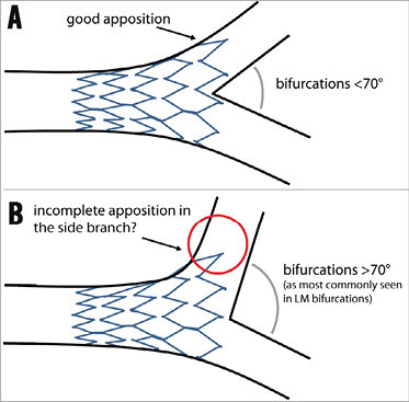
Figure 1. General concept of the Axxess stent. A) Concept of the Axxess stent: due to the conical shape of this self-deploying device, the stent adjusts to the natural anatomy of coronary bifurcation lesions, “flaring” into the distal main branch and side branch ostia, leaving the carina free from metal. B) A potentially less favourable anatomy including a large distal bifurcation angle (as is usually seen in left main bifurcations). In such a bifurcation anatomy, the distal diameter of the device might not be large enough to cover the side branch ostium fully (red circle), which may lead to difficulties in fully covering the side branch ostium with a second (overlapping) stent, if deemed necessary.
Tryton Side Branch Stent
The Tryton Side Branch Stent™ (Tryton Medical, Inc.) has been described in detail elsewhere5,20 and in the Online Appendix (Online Figure 2).
CLINICAL DATA AVAILABLE IN LEFT MAIN BIFURCATION LESIONS
The first reported data on the Tryton stent in the LM consisted of a retrospective analysis including 52 patients from nine European centres (SYNTAX score 20±8)22. The procedural success rate was 98%. The mean pre-procedural distal bifurcation angle was 65.5±18.7° (with 3D-QCA), which was not affected by stent placement (post-procedural angle was 65.7±16.8°). Acute gain on QCA was 1.52±0.86 mm in the LM and 0.92±0.47 mm in the side branch. At six-month follow-up, all-cause death occurred in three patients (6%), cardiac death in one (2%), MI in five (10%), and TVR in six (12%) with SB involvement in all cases. Definite ST was not observed. The six-month MACE (composite of cardiac death, MI and TVR) rate was 22%. These results showed that Tryton in combination with a DES in the main branch was a feasible strategy to treat distal LM bifurcation lesions. The acute angiographic result was predictable with an excellent acute gain in all segments. The overall event rate was low; however, all repeat revascularisations were performed due to in-stent restenosis of the bare metal side branch. It is important to note that the larger-sized Trytons were not yet available in this study period. After the larger-sized Trytons became available, a prospective registry including 30 patients was performed by the same study group, the results of which are expected soon.
THEORETICAL ADVANTAGES AND POTENTIAL DRAWBACKS
A treatment strategy with Tryton commits the operator to the two-stent approach, and Tryton is therefore not suitable for the provisional strategy which is the preferred approach in the majority of bifurcation lesions (Figure 2). The design of the Tryton accommodates the natural anatomy of the bifurcation, including the step-down in diameters from proximal to distal, due to the availability of a stepped delivery balloon in various diameters. Furthermore, the data above, as well as non-LM Tryton studies, did not show any indication that bifurcation angle influences procedural and angiographic outcomes, suggesting the stent is suitable for a wide variety of bifurcation angles. Another advantage of the device is, as suggested by the above and other previously published data, that the acute angiographic outcome is predictable with side branch access during the procedure23. Furthermore, not only does it simplify the culotte technique, but its use also reduces the amount of metal in the proximal main branch compared with culotte using two DES. Final kissing balloon dilatation (FKBD) is strongly recommended by the company, although a randomised trial is currently running an evaluation concerning whether the FKBD can be omitted when using Tryton, which may simplify the procedure even further24. The most important drawback is that the device is currently only available in a bare metal version, leading to an increased risk of repeat revascularisations of the side branch.
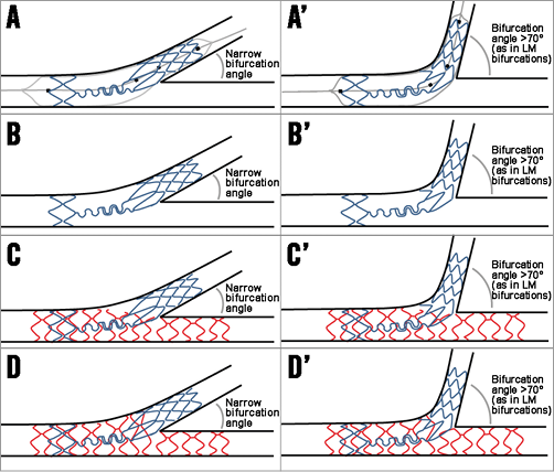
Figure 2. The general concept of the Tryton stent. A) An illustration of Tryton stent deployment. Note the four markers on the delivery system used to position the stent adequately. Also note the stepped delivery balloon accommodating the natural tapering of coronary bifurcations. B) An illustration of a deployed Tryton stent. C) An illustration after main branch stent placement (in red), after the proximal optimisation technique of the main branch stent to ensure adequate expansion and apposition of the main branch stent within the two Tryton wedding bands. D) An ideal illustration after final kissing balloon dilatation after side branch wiring through a distal main branch cell. A’) to D’) The same steps as in panels A) to D), but in a bifurcation with a large distal angle (as is commonly seen in left main bifurcations).
BiOSS
The Bifurcation Optimisation Stent System (BiOSS®; Balton, Warsaw, Poland) is described in more detail elsewhere in this supplement25 and in the Online Appendix (Online Figure 3).
CLINICAL DATA AVAILABLE IN LEFT MAIN BIFURCATION LESIONS
Bil et al reported on 12-month clinical and acute angiographic follow-up in 54 patients (average SYNTAX score 21.5±6.5, logistic EuroSCORE of 3.85±3.50), treated in two centres (Poland and Bulgaria) with the paclitaxel-eluting BiOSS Expert26. The true bifurcation (i.e., with significant involvement of the side branch) rate was 57%. The device success rate was 100%. All patients were treated with the provisional approach, with additional T-stenting using paclitaxel-eluting DES in 26% of cases. No deaths were observed. The overall MI rate was 14.8% (all asymptomatic periprocedural troponin rise), and the ST rate was 0%. Overall, TLR was observed in five patients (9.3%). Twelve-month QCA analysis (single-vessel software) showed an LLL of 0.20 mm in the proximal main branch, 0.26 mm in the distal main branch and 0.13 mm in the side branch. It is noteworthy that, of the five TLR cases, only one was clinically driven. These results show that the use of BiOSS in LM bifurcation lesions was feasible. So far no safety concerns have emerged: to date no ST has been reported. In addition, a registry was conducted with the sirolimus-eluting BiOSS LIM. A total of 74 patients were included in four centres in Bulgaria, Poland and Spain. Results from this registry are expected to be published soon.
THEORETICAL ADVANTAGES AND POTENTIAL DRAWBACKS
The first advantage of this device is that, by its stepped design, it conforms to the natural anatomy of the bifurcation with its inherent step-down in diameters13,27. An IVUS study on the device in non-LM bifurcations has suggested different mechanisms of lumen enlargement in coronary bifurcation lesions treated with the provisional approach between conventional DES and the BiOSS stent. Overall, a comparable luminal gain was observed, but the BiOSS stent was associated with less luminal compromise and plaque redistribution at the level of the SB in-flow in the bifurcation segment28. Although BiOSS implantation is performed according to the most recent EBC consensus, including the use of the proximal optimisation technique (POT) and FKBD, the stepped stent design and large cell opening towards the side branch might decrease the need for POT and FKBD. Another advantage is that it is a DES, although the sirolimus-eluting BiOSS LIM has an LLL which is ~two times the LLL seen in the CYPHER® sirolimus-eluting stent (Cordis, Johnson & Johnson, Bridgewater, NJ, USA). This may be explained by the strut thickness and sirolimus formulation; however, it has to be pointed out that no randomised comparison is available. In theory, due to the 0.9-1.5 mm distance between the proximal and distal stent parts, there could be a gap between the parts if the proximal-to-distal main branch angle is around 180 degrees (Figure 3A). However, most bifurcations have a proximal-to-distal bifurcation angle <180 degrees which will result in “bending” of the two stent parts, opening the stent cell towards the side branch ostium, and alignment of the two stent parts opposite the side branch ostium29 (Figure 3B). More studies are needed to evaluate the influence of this proximal-to-distal angle on the strut-to-vessel wall ratio in the main branch opposite the side branch ostium, which is similar (14.6%) to that of the total stent (15-18%), according to the manufacturer. To date, there are no signs of excessive restenosis at the site opposite the side branch ostium, as has been shown with the so-called patterns of restenosis in the large BiOSS left main cohort26 (Figure 3C).
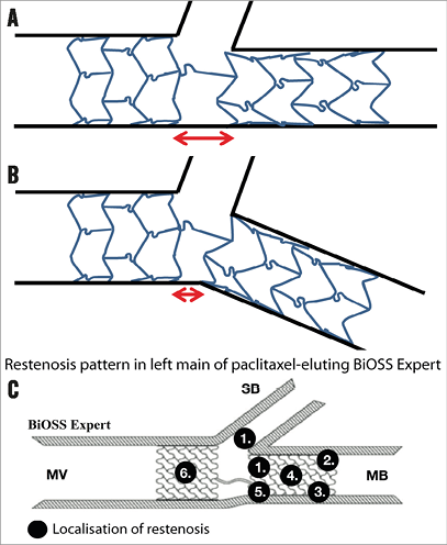
Figure 3. The BiOSS concept. A) An illustration of a BiOSS stent in a bifurcation lesion with a proximal-to-distal main branch bifurcation angle of 180 degrees. B) An illustration of a BiOSS stent in a bifurcation lesion with a <180 degrees proximal-to-distal main branch angle. This illustrates the concept of BiOSS in which, due to the bending, the stent is “opened” towards the ostium, while opposite the side branch ostium the proximal and distal parts of the stent will be aligned (this concept is indicated by the red arrows in panels A and B). C) The restenosis patterns as seen in the paclitaxel-eluting (BiOSS Expert) version in the left main. There is no clear predisposition for the region opposite the side branch at least suggesting the proximal and distal parts align well, not leaving a gap in between.
STENTYS
The STENTYS Self-Apposing® stent (STENTYS S.A., Paris, France) is described in detail elsewhere in this supplement4 and in the Online Appendix (Online Figure 4).
CLINICAL DATA AVAILABLE IN LEFT MAIN BIFURCATION LESIONS
Smolka et al published clinical outcome data on 24 patients (median SYNTAX score 20 [20.0-27.2]) with LM lesions treated with the paclitaxel-eluting STENTYS stent30. All patients had significant side branch involvement (Medina 1,1,1 in 45% and 1,0,1 in 55%). Device success was 97%. Disconnection of struts was performed in 75% of cases. An additional side branch stent was placed in 16% of cases. The final procedural success rate was 96%. Clinical follow-up was available up to 30 days during which period no adverse events were observed.
Clinical outcomes from a larger cohort were published recently by Briguori et al31. In this registry, 75 patients (average SYNTAX score 24±8, logistic EuroSCORE II 6 [interquartile range 2-54]) treated with STENTYS for LM bifurcation lesions and “tapered anatomy”, (i.e., >~1 mm difference in the diameter from the distal LM to the proximal LAD) were evaluated. Outcomes were compared with 75 propensity-matched controls treated with a second-generation balloon-expandable DES. The majority (57%) had Medina 1,1,1 lesions. The STENTYS was disconnected in 91% of cases and the side branch was stented in only nine cases (12%). Acute gain was higher with STENTYS than in regular DES in the polygon of confluence (3.67±0.59 vs. 2.88±0.86 mm, p<0.001). Although the final balloon diameter was larger in the control group, final cross-sectional area on post-procedural IVUS was significantly larger in all segments within the STENTYS than in the control. Although the two groups were matched for baseline reference vessel size, it has to be pointed out that the control group comprised entirely Chinese subjects, who may have smaller vessels than Europeans. One-year clinical outcomes were similar between the groups. In the STENTYS group, three deaths were observed (4.0%, all cardiac). The MI rate was 2.6%, and the repeat revascularisation rate was 1.3% (ST rate 2.6%). The cumulative event rate was 9.3%.
THEORETICAL ADVANTAGES AND POTENTIAL DRAWBACKS
One of the advantages of this device is that it will adjust itself to the natural step-down phenomenon of the bifurcation (Figure 4A- Figure 4D). The STENTYS expands further than the reference diameter for which it is indicated: the smallest-sized STENTYS (suitable for RVD range of 2.5-3.0 mm) expands up to 4.2 mm, the medium size (RVD range 3.0-3.5 mm) expands up to 5.3 mm, and the largest size (RVD range 3.5-4.5 mm) up to 6.6 mm, which is beyond the maximal expansion capacity of balloon-expandable DES32. This will probably lead to less carina shift, and POT may be less essential. Another advantage is the possibility literally to “open” the stent by disconnecting the connecting struts (Figure 4E, Figure 4F). If this is done in a distal stent cell, the stent part just proximal to the disconnection will be “flared” and appose itself to the lateral vessel wall of the side branch (Figure 4G). Stent distortion with overhanging struts into the distal main branch just distal to the disconnection is not expected due to the memory shape of the nitinol. Consequently, final kissing balloon dilatation might be less essential than in conventional balloon-expandable DES. However, a potential disadvantage is that, when a too proximal cell is crossed with a wire, there is not much advantage to be expected (i.e., no side branch ostium coverage) from the strut disconnection (Figure 4H). OCT might be useful to guide optimal cell re-crossing, as previously shown in balloon-expandable stents33.
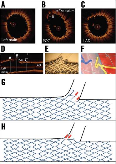
Figure 4. The STENTYS in bifurcation concept. A) - C) Optical coherence tomography (OCT) still frames after STENTYS placement in the left main (LM) – left anterior descending (LAD), including rewiring and side branch post-dilatation of the circumflex artery (RCx). Note the good apposition in the LAD, polygon of confluence (POC) and LM. D) Longitudinal view of the OCT pullback indicating the position of the OCT still frames of panels A) - C). E) The concept of disconnecting the connecting struts after which STENTYS “flares” into the side branch with good coverage and apposition in an in vitro model. F) An illustration of connecting struts being disconnected due to side branch balloon dilatation. G) The concept of disconnection and “flaring” of the side branch ostium. H) What theoretically may happen when the struts are disconnected by dilatation through a more proximal stent cell, after which the stent will not flare into the side branch and cover the ostium. Red arrows indicate both sides of the disconnected strut.
The Nile stent
The Nile stent (Minvasys, Gennevilliers, France) is described in detail elsewhere in this supplement5 and in the Online Appendix (Online Figure 5).
CLINICAL DATA AVAILABLE IN LEFT MAIN BIFURCATION LESIONS
To date no data have been published on the use of the Nile stent to treat distal LM bifurcation lesions. To the best of our knowledge, data are limited to 38 patients (of whom 32% were treated with the Nile CroCo, and 68% with the Nile PAX), as presented during EuroPCR 2013, Paris, France; presented by Dr Berland.
THEORETICAL ADVANTAGES AND POTENTIAL DRAWBACKS
One of the major advantages of this device in the LM is that it ensures access to the main and side branch during the procedure. There is no need to use jailed wires to secure the side branch during main branch placement (Figure 5A-Figure 5C). Furthermore, there is no need for wire re-crossing which might simplify the procedure considerably. A potential drawback of the use of this device is the occurrence of wire wrapping, often requiring re-wiring, although this might be a lesser problem for the LM. Another advantage of this device is the specific design of the proximal part of the side branch balloon, which prevents elliptical-shaped stent overexpansion in the proximal main branch during final kissing balloon dilatation, as seen with conventional stents34. The European Bifurcation Club recommends sizing the stent according to the distal main branch to prevent carina shift, and performing a POT after main branch placement to ensure adequate proximal stent expansion9,35. Because the Nile main branch stent is a straight stent, POT might therefore still be necessary (see red arrow in Figure 5C indicating the potential incomplete apposition). Although a DES version is available, no follow-up angiographic data are available on the Nile PAX and therefore it is difficult to judge whether the polymer-free paclitaxel coating is effective for the prevention of in-stent restenosis to the same extent as newer-generation DES.
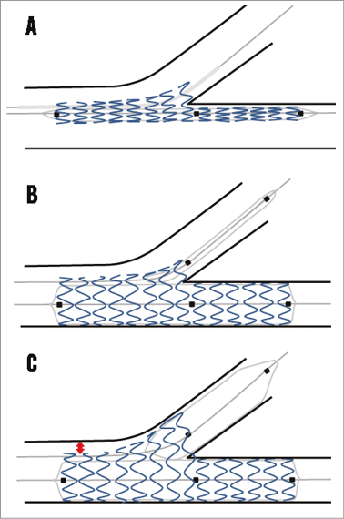
Figure 5. The Nile concept. A) The device is advanced over two wires (one in the distal main branch and one in the side branch) and positioned using the middle marker. B) An illustration of deployment using the main branch balloon after which the side branch balloon is advanced. Note that the proximal balloon marker is aligned with the main branch middle marker. Then, kissing balloon inflation can be performed. C) Theoretical outcome after final kissing dilatation. Due to the special design of the proximal part of the side branch balloon, the proximal main branch is not overstretched. However, because the stent is straight, there might be proximal malapposition (red arrow) if the sizing is performed according to the distal main branch, as recommended by the EBC. The proximal optimisation technique should be used to correct for this malapposition.
Conclusions
Distal LM bifurcation lesions remain a challenge for interventional cardiologists with worse clinical outcomes compared to ostial/mid-shaft LM lesions. Conceptually, dedicated bifurcation devices offer potential advantages which may improve clinical outcomes after PCI of LM bifurcations. However, data on dedicated devices in the LM are sparse and more studies are needed. It is conceivable that the efficacy of dedicated devices depends on specific anatomic features, and it is unlikely that one of the devices will provide the ultimate solution for every LM bifurcation lesion.
Conflict of interest statement
R.J. Gil is medical consultant of the Balton Company. P.W. Serruys is chairman of the Tryton IDE trial. The other authors have no conflicts of interest to declare.
Online Appendix. General description of stents
AXXESS
The Axxess™ stent (Biosensors Europe SA, Morges, Switzerland) is a conically shaped self-expanding nitinol platform coated with a biodegradable polymer (on the abluminal surface only) from which it elutes Biolimus A9, a lipophilic, semi-synthetic sirolimus analogue. It is designed to be deployed in the proximal main branch, covering and scaffolding the “lateral” parts of the distal ostia, leaving the carina free from struts (Figure 1). Placement is facilitated by one proximal marker and three radiopaque markers at the distal stent end. The distal branches can additionally be treated with DES if deemed necessary. The Axxess stent is currently available in 3.0 and 3.5 mm diameters (the 4.0 mm has been voluntarily withdrawn by the company to make improvements to the system). The 4.0 mm device was of particular interest for the LM, suitable for reference diameters between 3.75 and 4.25 mm. The largest size had distal flare end diameters of up to 10 mm. The 3.0 and 3.5 mm devices are available in 11 and 14 mm lengths, while the 4.0 mm device was available in 9 mm. The Axxess has no specific CE mark for the treatment of LM lesions.
TRYTON SIDE BRANCH STENT
The Tryton Side Branch Stent™ (Tryton Medical, Inc.) is a balloon-expandable cobalt-chromium slotted-tube bare metal stent. The stent has a unique design including three zones: 1) a distal side branch zone with a conventional tubular stent design; 2) a proximal main branch zone with two wedding bands anchoring the stent in the proximal main branch and a minimal amount of metal due to three undulating fronds allowing easy delivery of a DES in the main branch; and 3) a transition zone in between with three independently deformable panels covering and scaffolding the side branch ostium. The stent is a side branch first stent and is used in combination with a DES in the main branch (inverted culotte technique according to the MADS classification21). Accurate positioning is done by using four radiopaque markers on the stent delivery system with the stent placed in such a way that the carina is being positioned in between the two middle markers (Figure 2). The initial version of the stent was 19 mm in length and mounted on either a straight delivery balloon (diameter 2.5 mm) or a stepped balloon (Figure 2) with proximal (main branch) diameters of 3.0 or 3.5 mm, with a distal (side branch) diameter of 2.5 mm for both. However, to accommodate treatment of lesions located in the LM or large LADs, another version was introduced with side branch/main branch diameters of 3.0/3.5 mm and 3.5/4.0 mm. More recently, the “Tryton SHORT” was introduced, with a length of only 15 mm, shortening the proximal main branch zone by 4 mm (in sizes of 3.0/3.5 mm and 3.5/4.0 mm). This adjustment facilitated its use in the LM further, since the original Tryton design mandated a minimal LM length of >10 mm and the Tryton SHORT only 6 mm. The stent received CE mark in 2008, and in 2014 it also received a CE mark for LM lesions.
BiOSS
The Bifurcation Optimisation Stent System (BiOSS®; Balton, Warsaw, Poland) is a balloon-expandable stent made of 316L stainless steel with a strut thickness of 120 μm. It is available in a paclitaxel-eluting version (BiOSS Expert®) and a sirolimus-eluting version (BiOSS LIM®), both eluting from a biodegradable polymer. The stent consists of a proximal part and a distal part connected to each other with two connecting struts with a length of 0.9 or 1.5 mm (depending on stent size). The stent is available in lengths of 15, 18 and 23 mm. The stent is mounted on a semi-compliant stepped balloon (Bottle®; Balton) and is available in sizes ranging from 3.25-4.50 mm (proximal part) and 2.50-3.75 mm (distal part). For the larger sizes (4.5/3.75 mm and 4.25/2.5 mm diameters), used mostly in the LM, the length of the proximal part is 6.6 mm (15 mm device) or 9.6 mm (18 and 23 mm lengths), while the length of the distal part is 7 mm (15 mm and 18 mm lengths) or 12 mm (23 mm device). The device is positioned using three markers, one at the proximal and one at the distal end, and a third in the middle, at the “middle zone”, enabling exact stent positioning at the side branch ostium. If needed, the side branch can be treated with regular stenting techniques such as the T-stenting or T and protrusion (TAP) technique. The device has no specific CE mark for LM lesions.
STENTYS
The STENTYS Self-Apposing® stent (STENTYS S.A., Paris, France) is a 6 Fr compatible, self-apposing stent made from nitinol. It is delivered using a rapid exchange delivery system and deployed by retracting a sheath using a thumb slider on the handle. Positioning is facilitated by using two radiopaque markers on the delivery system indicating its proximal and distal ends. After deployment, the stent expands by itself until it reaches the vessel wall. The stent is available in bare metal, paclitaxel-eluting, and sirolimus-eluting versions. The DES versions elute their drug from the “ProTeqtor®” coating, a durable matrix of polysulphone (PSU) and a soluble polyvinylpyrrolidone polymer (PVP) that act as an excipient. The stent is available in three lengths (17, 22 and 27 mm), and in three sizes: a small-sized STENTYS (for RVDs ranging from 2.5 to 3.0 mm), a medium-sized STENTYS (for RVDs ranging from 3.0 to 3.5 mm), and a large-sized STENTYS (for RVDs ranging from 3.5 to 4.5 mm). The stent has a strut thickness of 102 microns (small-sized STENTYS) or 133 microns (medium-and large-sized STENTYS). The connecting struts can be disconnected by inflating a standard angioplasty balloon between struts towards the side branch. After disconnection, the stent will “flare” into the side branch until it reaches the lateral side branch vessel wall (Figure 4B, Figure 4E, Figure 4G) or up to its maximum expansion diameter, which is 6.6 mm for the largest device. If needed, the side branch can be treated with regular stenting techniques such as the T-stenting or T and protrusion (TAP) technique. The STENTYS stent has a CE mark, but not specifically for LM use.
THE NILE STENT
The Nile stent (Minvasys, Gennevilliers, France) is 6 Fr compatible and made of a cobalt-chromium L605 alloy with a strut thickness of 73 μm. It is available in a bare metal version (Nile CroCo®) and a polymer-free paclitaxel-eluting version (Nile PAX®). The paclitaxel is applied to the abluminal surface only, adding 5 μm to the strut thickness. The stent design incorporates a unique three-segment design with a side aperture located in the middle of the stent. The stent is pre-mounted on a dedicated delivery system with two independent balloon catheters, each with a rapid exchange lumen for two conventional guidewires (0.0014”). The procedure starts by wiring both distal branches. Positioning of the stent is done by matching the central radiopaque marker of the main branch delivery balloon with the ostium of the side branch (Figure 5A). Besides the central marker, there are two radiopaque markers which indicate the proximal and distal ends of the main branch and side branch balloon. Once the device is in the desired position, the stent is deployed by inflating the main branch balloon (Figure 5B). Then, the side branch balloon is moved forward into the side branch (through the side aperture) to perform kissing balloon dilatation (Figure 5C). The special design of the proximal part of the side branch balloon avoids overexpansion of the proximal main branch. The stent is available in lengths of 18 and 24 mm. The device is available in five different main branch/side branch diameters: 3.5/3.0 mm, 3.5/2.5 mm, 3.0/3.0 mm, 3.0/2.5 mm, and 3.0/2.0 mm. Currently, a dedicated LM device is under development. The device has no specific CE mark for LM lesions.
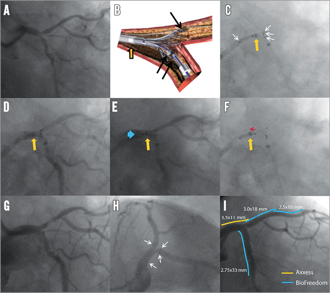
Online Figure 1. Case example of Axxess in left main. The angiogram shows a left main (LM) Medina 1,1,1, bifurcation lesion (A). Illustration showing the concept of delivery of the Axxess stent: positioning is facilitated using three radiopaque markers (black arrows) indicating the distal end of the stent, and another proximal marker (not shown in this panel) indicating the proximal end. Another marker indicates the distal end of the retracting sheath (orange arrow). C) After preparing the lesion according to operator preference, the Axxess is advanced over a single wire (i.e., use of jailed second wire up to operator’s preference), and positioned in such a way that two distal markers are seen in one distal branch and the third marker in the other distal branch (white arrows indicating the proximal and three distal markers). The sheath is retracted slightly, but the distal sheath marker (orange arrow) should not be retracted distal from the “point of no return” (middle of the stent as indicated by a middle marker on the catheter). Panel D shows the same as panel C but now with contrast injection (orange arrow is again the distal sheath marker). E) With the distal end of the sheath still distal to the mid point of the stent, the partially flared stent should then be gently advanced (blue arrow) until resistance of the carina is felt. F) After optimal positioning, the cover sheath is further retracted (indicated with red arrow) to deploy the Axxess stent (orange arrow indicating the distal end of the sheath being retracted proximal to the mid point of the stent). Panel G shows the acute angiographic result after Axxess placement and panel H shows the final result after additional stenting in the distal branches (white arrows indicating stent markers). Panel I shows the final angiographic result as seen using the same projection as in G with the relative positioning of the stents indicated by coloured lines.
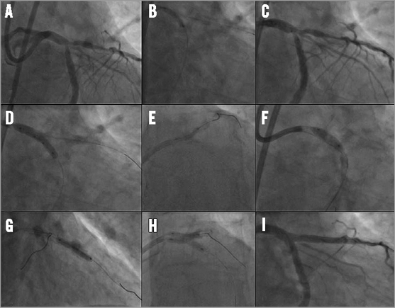
Online Figure 2. Case example of Tryton in left main. The angiogram shows a left main (LM) Medina 1,1,1, bifurcation lesion (A). The left anterior descending (LAD) artery and ramus circumflex (RCx) artery were wired and the RCx was predilated with a 2.5 mm balloon (B). Then, a 3.5/2.5×19 mm Tryton stent was positioned using the radiopaque markers with the carina being positioned in between the two middle markers (C), followed by Tryton placement using the stepped delivery balloon (D). The guidewire in the RCx was then retracted and advanced into the distal LAD and, after predilatation of the LAD (E) and retraction of the initial (jailed) LAD wire, a 3.5×18 mm DES was positioned in the LM-LAD (F). A second (overlapping) DES was subsequently used in the LAD (G). Finally, the RCx was re-wired and final kissing balloon inflation performed (H) with good final angiographic results (I). (Reprinted with permission from Magro et al22 © Europa Edition)
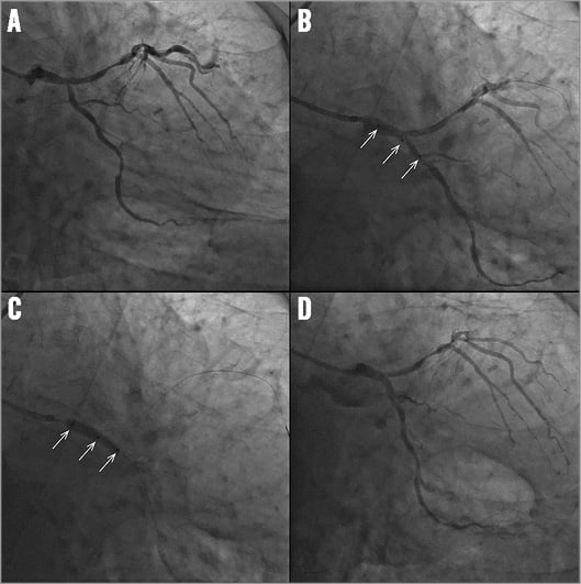
Online Figure 3. Case example of BiOSS in left main. Angiogram showing a left main (LM) bifurcation lesion with stenosis in the distal LM and ostium of the circumflex (A). BiOSS LIM® positioning using the three radiopaque markers (white arrows) (B). BiOSS LIM deployment (white arrows indicate three markers) (C). Final angiographic result after BiOSS LIM stent implantation (D).
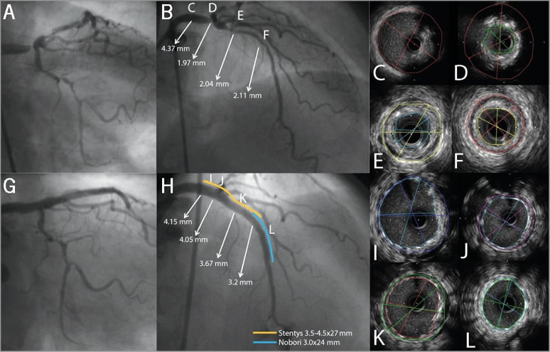
Online Figure 4. Case example of STENTYS in left main. Angiogram showing a Medina 1,0,0 left main (LM) bifurcation lesion (A & B). B) shows the lumen diameters, as assessed with quantitative coronary angiography (QCA), at different sites in the LM-left anterior descending (LAD) trajectory. The letters C-F in panel B correspond to panels C-F showing the IVUS images at these particular sites in the LM-LAD. Final angiogram shows good angiographic results (G & H). QCA showed that after treatment there was still a difference of almost 1.00 mm (from 4.15 mm in LM to 3.22 mm in LAD) in lumen diameter (H). The letters in panel H correspond to panels I-L showing well-expanded and well-apposed STENTYS in LM and LAD on IVUS (I-L).
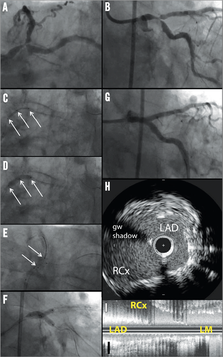
Online Figure 5. Case example of Nile stent in left main. Panels A and B show a Medina 1,1,1, distal left main (LM) bifurcation lesion. After wiring both distal branches, the system is inserted on the two guidewires and positioned using a proximal, a middle and a distal radiopaque marker (white arrows in C). The system stops at the carina, at which point the operator will feel resistance. Then, the main branch balloon is inflated, deploying the stent in the main branch (D). Then, the side branch balloon is advanced over the second wire placed into the side branch; positioning is done using two markers (white arrows) indicating the proximal and distal ends of the balloon (the proximal balloon marker should be aligned with the middle marker of the main branch) (E). A kissing inflation is then recommended (F). The delivery system is then removed, leaving the two guidewires in place and additional stenting can be performed at the operator’s discretion. Panel G shows a good angiographic result. Imaging with intravascular ultrasound shows a wide open ostium without jailed side branch struts, both in a cross-sectional (H) and in a longitudinal (I) view.