Successful PCI for chronic total occlusion (CTO) requires attention to subtle techniques. There is no simple way to open every type of CTO lesion. Crossing the CTO with the guidewire is the most difficult and important technique. Although guidewire selection and manipulation tactics are key issues, successful guidewire manipulation requires adequate preparation, including guiding catheter selection and angiographic techniques.
Recently, the retrograde approach from the donor artery of the collateral circulation was developed as a systematic method of crossing the lesion. Although there is an excellent summary by G. Stone et al, I would like to introduce here the practical technique for guidewire crossing CTO lesions.
Creating the right environment
Guiding catheter selection
The tip shape of the guiding catheter is critically important. To maintain effective guidewire manipulation, coaxial orientation, stability and backup force of the guiding catheter are much more important than the ease of engagement itself. Attention to these factors will allow proper focus on guidewire manipulation, including pushing, without the guiding catheter being forced out of the coronary ostium.
For the right coronary artery (RCA) the Judkins right type may be optimal for the artery which has a downward take-off. The Amplatz left type, which is a half size smaller than the size fitting the left coronary artery (LCA) is also an optimal guiding catheter for RCA. For male Asian patients, BriteTipTM, which has a deeper secondary curve (Figure 1); and for female Asian patients, Launcher SAL-1 is convenient (Figure 1).
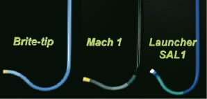
Figure 1. Amplatz Left Short Tip (AL1 ST) guiding catheters from different companies. A: Brite-Tip AL1ST. B: Mach1 AL1ST. C: Launcher SAL1.
It is important to note that guiding catheter shapes can vary significantly by company, even if the same name is used.
For (left anterior descending) LAD proximal lesions, the Judkins short tip, and for other of LAD and left circumflex (LCX) lesions, an extra-backup type or Voda type can be effective.
Anchor technique for guiding catheter stabilisation1,2
The anchor technique means that balloon inflation is done in the side branch (Figure 2).
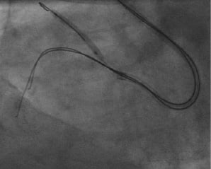
Figure 2. Anchor technique; RCA proximal CTO. Amplatz L-1 was not stable during pushing of the guidewires (seesaw wiring, see below). To stabilise the guiding catheter, a soft tip guidewire was advanced into the small conus branch and dilated by 2.0 mm balloon with 8 atmosphere.
This technique may be effective when the stability of the guiding catheter is either insufficient or unable to be achieved.
Bilateral angiography for diagnosis
For the patient who has collateral flow from a contra-lateral coronary artery, it is helpful to identify the intended entry point, vessel pathway, the intended exit point, and special relationship that each of these has to each other.
Biplane angiographic equipment
Although single-plane angiographic equipment with multi-angle angiography is acceptable, a biplane machine is much more effective in determining the correct direction , as well as reducing contrast media consumption. As a general rule, the two projection angles should be perpendicular to the long axis of the region of interest (ROI) in the target vessel. And these two projection angles are better if they are orthogonal to each other. Representative projection angles for various ROI are shown in Table 1.
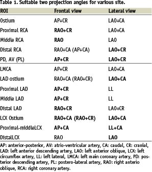
In general, one projection can be selected to optimally open the angle between the main and side branch. In the other projections, branches may be overlapped, but with this projection direction control is easier.
IVUS
When the stump cut-off is abrupt and flat, and the entry point is not identified by an angiogram, the centre of the stump should be tried as an entry point. In this situation, it is the invisible dimple of a conventional wire, not the sleek hydrophilic-coated tip that is identified. If the artery is large enough, and the entry point is at a side, rather at the end of a stump, intravascular ultrasound (IVUS) can be used to identify the entry point3 (Figure 3).
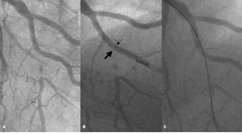
Figure 3. Confirmation of the entry point with IVUS. A: CTO in LAD at the bifurcation of the diagonal branch. The stump was not recognised. B: IVUS was introduced and the transducer was stopped where the LAD ostium was observed and angiography was obtained. The position of the transducer (small arrow) showed the entry point (Large arrow). C: The guidewire could be crossed.
Contralateral injection and bilateral angiography during guidewire advancement
Contralateral injections are also essential for CTO which has collateral from contralateral circulation. We cannot confirm that the guidewire has crossed the lesion to the distal true lumen, or through the subintima, without contralateral injection. We can correct the guidewire route from the subintima to the true lumen by using the collateral vessel as a landmark. Although tactile sensation of the guidewire may allow recognition of the true lumen, it is not always a reliable reference.
In some situations, bilateral simultaneous angiography is also very useful in confirming that the guidewire route is through the true lumen, and to recognise the subtle gap between true lumen and guidewire route position.
Over-the-wire (OTW) catheter
Over-the-wire catheters, such as micro-catheters or small size balloon catheters, are also essential tools. The OTW catheter tip can be advanced to the portion near the occlusion by using a softer guidewire such as the Intermediate, Miracle 3.0 g guidewire and so on. The guidewire can then be exchanged to a stiffer wire such as a Conquest (Confianza) Pro or Miracle series, without any risk of injury in the proximal artery. OTW catheters provide stronger back-up force and allows guidewire movement.
Guidewire crossing strategies
Guidewire tip shape
To cross any total occlusions, the shape of the distal guidewire tip should be as small as possible, 1.0-1.5 mm, with an angle of 30 to 45 degrees. With larger 4-5 mm tip curve, controlling the precise direction in the occlusion site becomes difficult, and there is also the risk of vessel wall injury, especially with sharper guidewires. For better control, the guidewire may have a second gentle curve (Figure 4) which functions as a curve in the bent portion and a straight line in the linear portion.
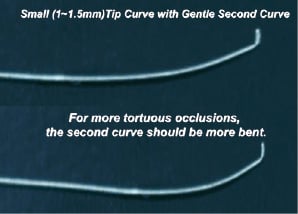
Figure 4. Tip Curves for CTO Lesion. In general, for the chronic occlusions, the tip curve should be as small as possible. Proximal second gentle curve is effective for the tortuous occlusion.
Because this second curve tends to straighten during procedure, some operators like kinking the guidewire shaft.
First-line guidewire selection to the micro-channel or soft plaque occlusion
If the micro-channel can not be clearly visualised, a polymer hydrophilic coated guidewire (Whisper, PT2, or Fielder) may be selected. Exploration of the micro-channel should be slow and gentle. If it cannot be seen, an intermediate type or Miracle 3.0 g guidewire can be used to bring the OTW catheter tip to near entry point and to explore the occlusive route composed by soft plaque.
Penetrating and drilling strategy
There are two strategies for crossing a CTO: the drilling or the penetrating strategy. In the drilling strategy, a 0.014 inch-tip guidewire is advanced by active rotation and tapping. If the crossing is unsuccessful, the guidewire can be exchanged successively from intermediate type or Miracle 3.0 g guidewires to stiffer wires (e.g. Miracle 4.5 g, Miracle 6.0 g and Miracle 12 g [Asahi Intec, Seto, Japan]).
For the drilling strategy, as in the first step of the penetrating strategy, an intermediate or a Miracle 3.0 g wire is used. If crossing fails, a stiffer and sharper wire with hydrophilic coating (sparing tip ball) such as the Conquest (Confianza) Pro wire (Asahi Intec, Seto, Japan) or a Cross It 400 wire (ACS Santa Clara CA, USA) can be selected to penetrate rather than drill the lesion. The rotating motion should be minimised (<90 in each direction) to maintain directional control. The manipulation should begin with an extremely light touch, gradually increasing.
My own preferred strategy is the penetrating strategy, which has become more prevalent recently in Japan.
The basic concept of the penetrating strategy is that using a guidewire more pliable than the lesion, and using a force exceeding the tip stiffness, the guidewire tip can be easily bent and advanced into the softer subintimal space (Figure 5).
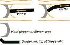
Figure 5. If the guidewire with penetrating force weaker than the plaque is pushed with the force larger than the tip stiffness, the guidewire tip becomes bent and slips into the subintima.
A guidewire with a penetrating force exceeding resistance of the lesion should be used, and using less force than the tip’s stiffness. For the harder lesion, a guidewire having a stronger penetration force should be used, and this stronger guidewire has been developed. Guidewires using this concept include: Conquest (Confianza) Pro 12 (tip thickness; 0.009”, tip stiffness 12 g), Conquest (Confianza) Pro 8-20 (tip thickness; 0.008”, tip stiffness 20 g).
The most important manipulation tactics involve patiently exploring the entry point with these wires, while maintaining the right direction. Buckling of the wire must be avoided.
Parallel wire method: See-saw wiring4,7
When the wire tip goes into the subintima or outside of the vessel around the exit point (Figure 6 A-H), the second wire is advanced leaving the first wire in place (the parallel wire method).
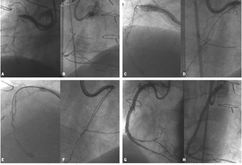
Figure 6. A,B: CTO lesion with bridging collateral in proximal RCA, shown in LAO (A) and LAO (B) views before intervention with seesaw wiring technique (Figure 7).
Figure 6. C,D: Parallel wire method or seesaw wiring. (C) (LAO view) and (D) (RAO view) show that the wire is deviated from the true lumen, a little rightwards in C and leftward in D.
Figure 6. E,F: Parallel wire method or seesaw wiring. Leaving the first wire In place as a landmark, a second wire is advanced and directed into the true lumen. The second wire is viewed at the left and right of the first wire, respectively in E (LAO view) and F (RAO view).
Figure 6. G,H: Parallel wire method or seesaw wiring. G (LAO view) and H (RAO view) show post- stenting angiograms.
(From Advanced Interventional Cardiology, 2nd edition. Chapter 10. Blackwell Publishing, New York, USA.)
With the existence of this landmark, the operator can direct the wire tip more easily in the direction of the true lumen. With the parallel wire technique, if the operator intends to use only one support catheter, it should be pulled back and reinserted into the target vessel again with the second wire. If the operator uses two support catheters at a time, the procedure becomes simpler. If it is difficult for the second wire to enter the true lumen, the roles of two wires (Figure 7 A-D) can be exchanged.
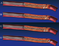
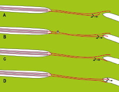
Figure 7. Seesaw wiring using two over-the-wire catheters at a time (A,B) to perform the parallel wire method can avoid complex exchange procedure of over-the-wire catheter. We can change the role of each guidewire very easily. If the second guidewire can not get the true lumen (C), we can exchange the functions of two wires. Namely, we can use the second wire as a landmark, and the first guidewire one as a penetrating one again (D).
Using the parallel wire method with two support catheters is called “See-saw Wiring”. The operator is able to move each of the two wires independently. This method introduces fluid (blood) into the otherwise dry occlusion site, triggering the hydrophilic mechanism (slippery when wet) and thus preventing the hydrophilic wires form sticking to each other.
Retrograde approach
Recently the retrograde approach has gathered interest. “Retrograde approach” is the general term for advancing a guidewire through the donor artery of collateral flow or through the graft to the open the total occlusion from behind. There are three strategic concepts in the retrograde approach (Figure 8).
Three concepts of retrograde approach
First, the tip of the guidewire used in retrograde can become a landmark of the distal exit point (Figure 8 A,B) In many cases, the tip of guidewire used in retrograde is a much more accurate landmark than contrast media filled by collateral circulation because the guidewire can be seen through the whole cardiac cycle during guidewire manipulation. It makes the guidewire advancement much more precise and also reduces contrast media consumption.
Second, the retrograde guidewire can be advanced into the occlusion site and break down the distal fibrous cap to create a channel from the distal true lumen to the occlusion site (Figure 8 C,D). The channel can be made by balloon inflation or damage by microcatheter tip from the retrograde approach. If the antegrade guidewire penetrates the subintima, the channel at the exit point may also be in the subintima. Even if it is very difficult to penetrate from the subintima to the true lumen, it is relatively easy to direct the guidewire tip to another part of subintima. Therefore, a hole made at the exit point allows the antegrade guidewire to reach the distal true lumen with much more ease.
If the retrograde guidewire manipulation is easier than antegrade, the proximal entry point can be broken (Figure 8 E,F).
The third concept is the direct crossing of the lesion through the true lumen (Figure 8 G,H).
In all three of these scenarios, the final guidewire must cross from the antegrade approach to deliver the stent(s).
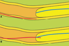
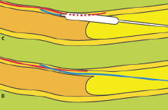
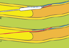
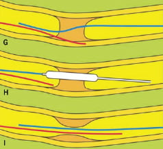
Figure 8. Retrograde approach. A,B: The retrograde guidewire tip can be used as a landmark of distal exit point. In this case, the guidewire tip is located in the distal true lumen. C,D: Channel from distal true to occluded false/true lumen E,F: Channel from proximal true to occluded false/true lumen.G,H,I: Direct crossing from distal to proximal true lumen.
Guiding catheters for the retrograde approach
Because the distance from the ostium of donor artery of the collateral to the exit point may be too long, microcatheter or balloons may not reach the exit point. The 100 cm long catheter can be cut, or an 85 cm long guiding catheter can alternatively be used. By femoral approach, in tall patients and/or patients with tortuous aorta, 85 cm guiding catheter may be too short and even cutting may not provide sufficient working length. For the shorter guiding catheter, the brachial approach is recommended, especially in large patient. To effectively set up a shortened guiding catheter system, it should be cut and connected by cut sheath of one size smaller than the guiding catheter (Figure 9).
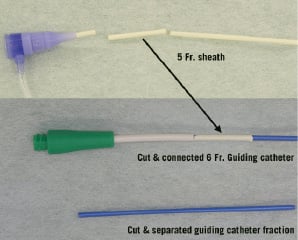
Figure 9. Cutting and re-connecting a guiding catheter.
Suitable collateral vessels which can be used for retrograde approach
The suitable conditions of collateral are:
– visible collateral connection by angiography are present
– septal connection is better, to prevent tamponade in case of vessel perforation
– collateral vessel is not too tortuous.
Guidewire crossing through the collateral vessel
Usually an over-the-wire (OTW) catheter, balloon or microcatheter is used for advancing the guidewire. Hydrophilic polymer-based guidewires are suitable for crossing the collateral connection. guidewire tip-shape must be changed according to the tortuosity of particular site. After the guidewire crossing, the OTW catheter should be used for exchange of the guidewire or balloon dilatation at the distal exit point. In case of difficulty in crossing the collateral, balloon dilatation with a small balloon (eg 1.25 mm), and by low pressure (eg 2Atm) may be necessary to help the balloon cross.
Guidewire advancement into the occlusion site from the exit point
In some cases, it is possible to cross the lesion directly to the proximal true lumen by the hydrophilic floppy guidewire. In the majority of cases, for the stiffer guidewire, guidewire exchange is required.
Inflate the balloon catheter to make a channel or to break the distal fibrous cap
Inflation by 1.25 mm to 2.5 mm balloon may be enough to introduce the antegrade guidewire into the distal true lumen. In some cases penetration by only the microcatheter tip may be effective.
Guidewire crossing from the antegrade approach
The technique and guidewire used in antegrade approach may be same as the standard technique.
IVUS-guided penetration of the guidewire
If the antegrade approach cannot make a re-entry from the false lumen, and the retrograde approach has failed, IVUS-guided penetration may be helpful to make a re-entry.3 In this technique, after dilatation with 1.5 mm balloon, the IVUS catheter is introduced into the false lumen. By observing the precise location of the true lumen and guidewire tip by IVUS, the guidewire tip can enter the distal true lumen.
After guidewire crossing
After the guidewire crossing by any method, the fact of whether the distal guidewire entered the distal true lumen or not should be confirmed by collateral angiography and guidewire movement. When the guidewire is advanced in the distal lumen (true or subintimal lumen), the guidewire tip should be directed to the inner side of the vessel curve. The guidewire should be located inside of the contrast media opacification of the distal true lumen. Also the guidewire should be smooth, not be bent, or sticking when it is advanced by a light touch. If any sticky tactile sensation is felt, there must be confirmation that the guidewire tip is not located in the true lumen. If the guidewire tip is not inside the true lumen, the parallel wire method or see-saw wiring should be performed to get another route.
The most important rule to remember in CTO cases is that no matter how close to the true lumen, a false lumen will always be false lumen. Confirmation of the true lumen by multiple methods is essential.