Abstract
Transcatheter heart interventions are expanding, and structural procedures are becoming more complex. This makes detailed visualisation and characterisation of cardiac anatomy and pathology increasingly important. As a result, there is a growing interest in interventional imaging for procedural guidance. Specifically, there is an increasing interest in using intracardiac echocardiography (ICE) as a complementary or alternative tool to transoesophageal echocardiography. Furthermore, new-generation three-dimensional matrix array ICE probes provide the possibility of obtaining multiplanar reconstruction imaging, playing a crucial role in structural heart interventions. To date, we still need guidelines that summarise the technical details of the most used ICE probes and that standardise procedure protocols. The purpose of this expert review is to provide an overview of ICE technology, describe the technical characteristics of the available probes, and present a review by a group of experts on their use in guiding structural heart interventions based on global clinical experience.
In recent years, indications for percutaneous structural heart disease (SHD) interventions have expanded significantly, and transcatheter procedures have become increasingly complex. Over the past decade, intraprocedural two-dimensional (2D) and three-dimensional (3D) transoesophageal echocardiography (TOE) have been widely used to assist in percutaneous SHD interventions. The increasing complexity of SHD procedures makes accurate visualisation and characterisation of the morphology and pathology of anatomical target structures mandatory for successful procedures. As a result, there is increasing interest in the use of new imaging techniques, particularly intracardiac echocardiography (ICE), for guiding procedures. With its high image resolution, close placement to the target area or device, and potential to perform procedures with local anaesthesia only, ICE is an intriguing alternative to TOE, which requires general sedation1. In high-volume centres, procedure duration and length of hospital stay also can be shortened by using ICE without significantly increasing the periprocedural complication rate12345. With the introduction of 3D ICE probes, many of the limitations associated with conventional TOE can be overcome. These 3D capabilities allow for improved visualisation of dynamic cardiac structures and better positioning of catheters and devices during interventional procedures (Central illustration). Data have shown that ICE can be safely used for guiding ablation of cardiac arrhythmias, atrial septal defect (ASD) closure, left atrial appendage occlusion (LAAO), transcatheter aortic valve implantation67, mitral and tricuspid transcatheter edge-to-edge repair (M-TEER and T-TEER, respectively), transcatheter tricuspid valve replacement (TTVR), and percutaneous pulmonary valve replacement18. However, there is no universally accepted standard for ICE-guided imaging across different SHD interventions. This underscores the need for education and training to ensure optimal and effective use of ICE during transcatheter interventions. This expert review aims to present the latest technical developments of ICE probes and to provide standardised approaches for different transcatheter procedures based on current clinical experience.
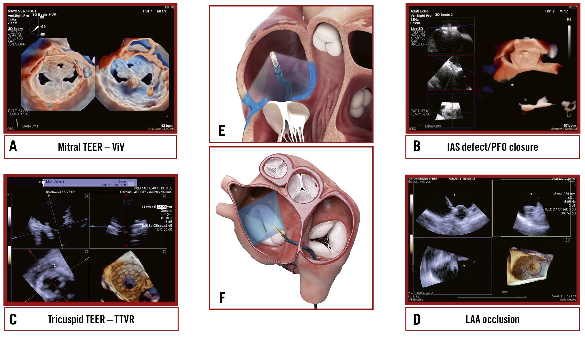
Central illustration. Current landscapes on 3D ICE utilisation. An overview of the key structural heart interventions that increasingly utilise 3D ICE: (A) mitral TEER/ViV; (B) IAS defect/ PFO closure; (C) Tricuspid TEER/TTVR; (D) LAAO. E) An illustration of the ICE probe’s position during imaging of the tricuspid valve. F) An illustration of the ICE probe’s position during imaging of the mitral valve. 3D: three-dimensional; ICE: intracardiac echocardiography; IAS: interatrial septum; LAAO: left atrial appendage occlusion; TEER: transcatheter edge-to-edge repair; TTVR: transcatheter tricuspid valve replacement; ViV: valve-in-valve
Evolution of imaging for SHD interventions
TOE
Cardiovascular imaging modalities, such as TOE, are valuable tools for diagnosing and treating SHD9. The integration of 3D techniques, such as multiplane imaging, live multiplanar reconstruction (MPR), and photorealistic imaging in TOE, has been proven to be extremely beneficial10. Multiplane imaging uses simultaneous views of separate planes and unlimited combinations of tilting and rotation to visualise cardiac structures. Live 3D MPR enables real-time (RT) 3D visualisation of structures from multiple angles, which reduces parallax errors and provides views that are otherwise impossible to achieve with conventional 2D imaging. This enables a more precise and efficient analysis of the anatomical structures and their relationships with neighbouring structures. Despite these improvements in TOE technology, there are still some limitations. The posterior position of the TOE probe in the oesophagus may limit its ability to image far-field structures in the anterior heart and chest, such as the tricuspid valve (TV). Specifically, structures on the right side of the heart can be masked by shadowing from a prosthetic material (e.g, a mitral ring or an occluder in the interatrial septum) or calcification (e.g., aortic valve calcification) on the left side of the heart. In addition, the TOE probe also may interfere with the visualisation of structures on fluoroscopy. Furthermore, TOE requires the use of sedation or general anaesthesia to allow for oesophageal intubation for an extended time, increasing the risk of oesophageal injuries. Finally, some patients with oesophageal pathologies (achalasia, stricture, scleroderma, Mallory-Weiss tear or diverticulum), after oesophagus resection, inability to intubate (cervical and upper airway pathologies) or who are at increased risk of upper gastrointestinal bleeding (such as those with oesophageal varices) have absolute contraindications for a standard TOE probe11. Although the use of mini-TOE probes has been proposed in this scenario, ICE represents a potential alternative that may even allow performing the intervention under local anaesthesia only.
3D ICE
In certain scenarios, integrating ICE, as opposed to TOE, into intraprocedural imaging guidance can notably streamline workflow1213. For example, transcatheter LAAO, patent foramen ovale (PFO) closure, and mitral valve-in-valve (ViV) implantation can all be performed safely and effectively with local anaesthesia and 3D ICE guidance only. Advantages to this approach include more flexibility when planning procedures, eliminating the need for a general anaesthesia team, reduced burden on the intensive care unit, reduced turnover time in the cath lab, and the ability to perform TOE-free procedures (particularly in patients with absolute contraindications to this imaging technique)414. Furthermore, there is the potential for same-day discharge post-procedure, which could result in reduced overall costs and mitigate patient susceptibility to delirium or nosocomial infections in the intensive care unit15.
For other procedures, such as transcatheter TV repair or replacement, 3D ICE is typically complementary to TOE16. TOE is the gold standard for TV imaging, but as previously noted, the posterior positioning of the probe relative to the valve can result in far-field tangential views with acoustic shadowing from other heart structures. Given its insertion via the femoral vein and ease of positioning within the right atrium (RA), the 3D ICE probe provides enhanced visualisation of the tricuspid leaflets and annulus (Figure 1, Moving image 1). Nevertheless, it is important to note that despite these advantages, 3D ICE imaging cannot entirely replicate all TOE views, particularly the transgastric short- and long-axis views, underscoring the ongoing clinical utility of TOE in numerous scenarios17. However, this may change in the future, depending on the imaging needed for a specific TV prosthesis implant.
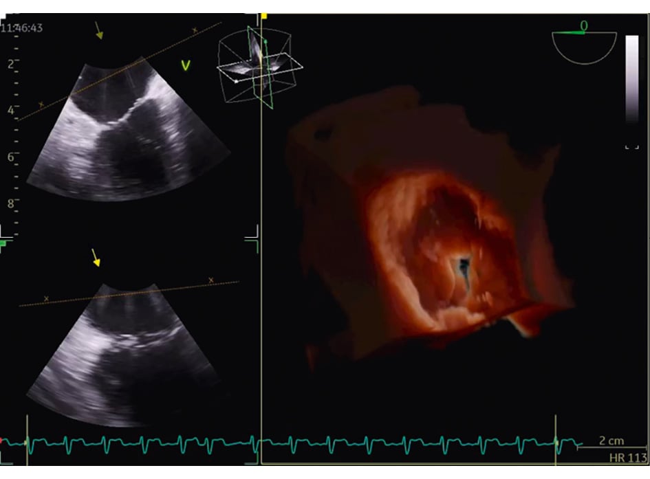
Figure 1. Three-dimensional reconstruction of the atrial view of the tricuspid valve.
3D TOE versus 3D ICE
3D TOE probes are equipped with larger matrix arrays, resulting in superior spatial and temporal resolution compared to 3D ICE probes. Furthermore, TOE offers a greater maximum 3D volume size. Compared to TOE, the spatial resolution of ICE 3D probes degrades along the axis perpendicular to the catheter’s long axis (at a 90-degree omniplane angle) due to the physical limitations of the transducer array18. Hence, when utilising TOE, the quality of biplane imaging is superior across all angles relative to the transducer array. As a result, to achieve optimal biplane imaging on 3D ICE, it is essential that the imaging planes closely align with the diagonal across the matrix array. Initial experiences with three-/four-dimensional mini-TOE probes have recently been published, with promising results in terms of safety, feasibility and tolerability. However, there are currently no direct comparisons with 3D ICE19. Another significant factor to consider pertains to the cost-effectiveness ratio associated with using 3D ICE compared to 3D TOE. Currently, 3D ICE catheters are single-use devices and are more expensive than using TOE. However, this cost is partially offset by the potentially lower costs associated with a less invasive procedure and the ability to avoid general anaesthesia in some cases. Further studies are needed to understand better the impact of this factor on the widespread use of 3D ICE (Table 1).
Table 1. Comparison of TOE and ICE in the setting of SHD interventions.
| TOE | ICE | |
|---|---|---|
| Procedure invasiveness | Semi-invasive | Invasive |
| Personnel requirements | Dedicated echocardiographer | Dedicated interventionalist and/or dedicated echocardiographer |
| Sedation requirements | General anaesthesia | Local anaesthesia |
| Integration in catheterisation laboratory | Requires additional equipment and space | Requires additional equipment and space Quick cath lab turnover |
| Imaging advantages | High-resolution imaging Biplane imaging/MPR Incremental value for 3D | High-resolution imaging Biplane imaging/MPR Incremental value for 3D Continuous imaging without interfering with fluoroscopy Advantages in specific settings (e.g., TV) limiting acoustic shadowing Superior right-sided cardiac imaging |
| Imaging disadvantages | Limited imaging of anterior structures (e.g., TV) Acoustic shadowing of prosthetic valves Mechanical traumatism on the oesophagus Limited access to oesophagus pathologies | Limited field of view Lower frame rate Lower volume of acquisition for certain technologies |
| Costs | Reasonable | High (limited reusability of the catheter) |
| Supportive data | Standard of care for most SHD interventions | Established utility for ASD/PFO closure and LAAO Emerging data on the feasibility of guidance of other SHD interventions |
| 3D: three-dimensional; ASD: atrial septal defect; ICE: intracardiac echocardiography; LAAO: left atrial appendage occlusion; MPR: multiplanar reconstruction; PFO: patent foramen ovale; SHD: structural heart disease; TOE: transoesophageal echocardiography; TV: tricuspid valve | ||
Basis of 2D ICE imaging
Understanding 3D intracardiac imaging requires knowledge of 2D imaging and its primary views. Figure 2 schematises the main views of 2D ICE, presenting a drawing on the left and the corresponding echocardiographic image on the right. Beginning with venous access (either femoral or transjugular), the ICE probe is advanced to the RA, which allows for a step-by-step examination of various cardiac structures. Due to the limited ability to visualise structures of the left heart, particularly the left atrial appendage (LAA), from the RA, it has become common to position the ICE probe in the left atrium. The ability to guide transseptal puncture (TSP) using ICE and to position the ICE probe in the left heart sections has paved the way for percutaneous interventions on the mitral valve and atrial appendage with the assistance of ICE. A clear step-by-step approach is essential for safely and effectively performing a TSP at a specific location within the fossa ovalis. Table 2 summarises the main steps of ICE-guided TSP.
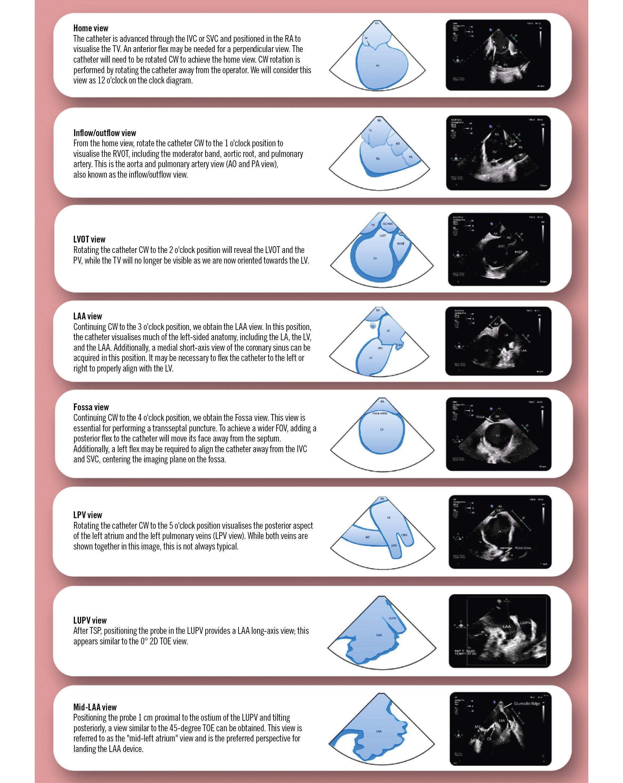
Figure 2. Schematic representation of the main 2D ICE views. 2D: two-dimensional; AO: aorta; CW: clockwise; FOV: field of view; ICE: intracardiac echocardiography; IVC: inferior vena cava; LA: left atrium; LAA: left atrial appendage; LPV: left pulmonary vein; LUPV: left upper pulmonary vein; LV: left ventricle; LVOT: left ventricular outflow tract; PA: pulmonary artery; PV: pulmonary valve; RA: right atrium; RVOT: right ventricular outflow tract; SVC: superior vena cava; TOE: transoesophageal echocardiography; TSP: transeptal puncture; TV: tricuspid valve
Table 2. Main steps of ICE-guided transseptal puncture.
| ICE-guided transseptal puncture |
|---|
| The transseptal system is retracted from the SVC into the RA while the ICE maintains a view of the SVC. |
| From this view, the operator can easily confirm when the transseptal sheath enters the fossa ovalis. It also confirms tenting of the septum in the fossa ovalis and the superior-inferior position of the transseptal sheath. |
| Once the transseptal system is tenting the fossa ovalis, the anterior-posterior position of the transseptal needle can be visualised in two different ways: |
| Clockwise rotation of the catheter moves the imaging plane to explore the posterior part of the septum (confirmed by identifying the LUPV) while counterclockwise rotation shows the anterior part of the septum (confirmed by identifying the aortic root) |
| or |
| Keep the transseptal system stable in this position and move the ICE probe to the “aortic view” |
| These two ICE views reveal if the tenting is located in the anterior or posterior fossa ovalis. |
| To achieve a more posterior position, the transseptal sheath should be rotated clockwise. |
| It is recommended to advance the needle using an anterior-posterior fluoroscopy view and to perform the puncture under both fluoroscopy and ICE guidance. |
| ICE: intracardiac echocardiography; LUPV: left upper pulmonary vein; RA: right atrium; SVC: superior vena cava |
Evolution of 3D ICE catheter technology
There are currently two conceptually different ICE catheters available: rotational catheters and phased-array catheters1. The former are primarily used for electrophysiological procedures, while phased-array catheters are steerable and better suited for SHD interventions. They have a handle with three rows of knobs, which are used to manipulate the catheter and the 64-element phased-array ultrasonic transducer on its tip. These catheters can flex and be fixed in four directions (anterior/posterior, left/right). The technological evolution of phased-array catheters over the past decade has led to their progressive and increasingly important use in intraprocedural interventional SHD imaging. The ACUSON AcuNav V catheter (Siemens Healthineers) was the first commercially available ICE catheter with 3D imaging capabilities. It allows for 22° to 90° volumetric single-beat 3D imaging and can rotate the image in multiple planes. However, low frame rates and a narrow sector volume may limit full structural imaging18. The introduction of the full sample matrix array transducer represented a major step forward in 3D technology, significantly improving the spatial resolution of the transducer and its penetration320. However, this type of 3D imaging does not provide RT imaging, and the acquisition and reconstruction take a few minutes, which renders it unsuitable for a procedure. The fundamental innovation that made the use of 3D ICE routine in SHD procedures was the addition of the fourth dimension: time (or RT 3D imaging). The implementation of RT volumetric imaging enables MPR visualisation of target cardiac structures, thereby greatly expanding the potential of intracardiac imaging to guide percutaneous procedures. Currently, there are three available 3D ICE catheters: the ACUSON AcuNav Volume (Siemens Healthineers) (Figure 3A), the VeriSight Pro (Philips) (Figure 3B), and the NUVISION (Biosense Webster) (Figure 3C). Each catheter has slightly distinctive features as noted in Table 3. All three catheters have multiple imaging modalities, including 2D imaging, colour-flow Doppler, RT 3D echocardiography, RT 3D colour-flow Doppler, spectral Doppler, and RT MPR.
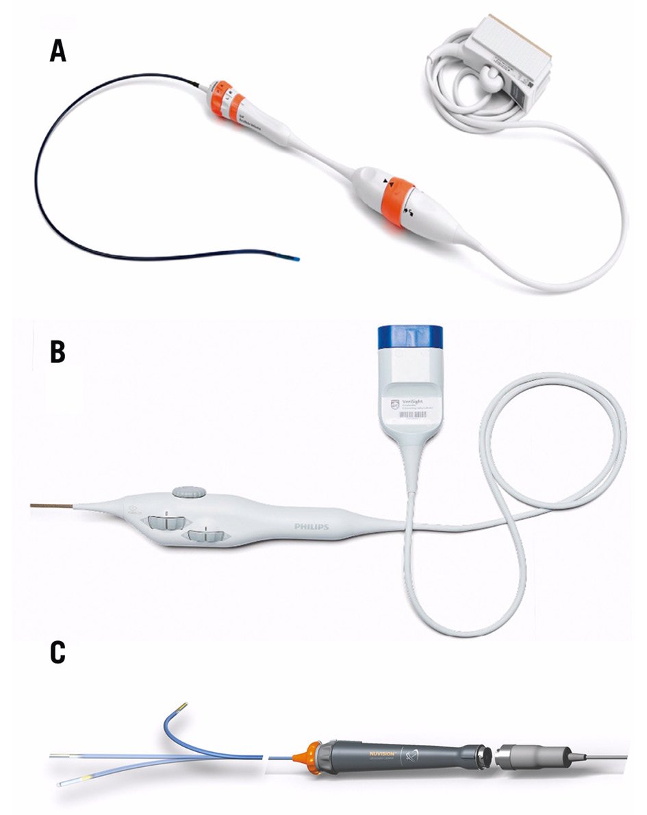
Figure 3. Currently available 3D ICE catheters. A) The ACUSON AcuNav Volume ICE catheter (reproduced with permission from Siemens Healthineers); (B) the VeriSight Pro ICE catheter (reproduced with permission from Philips); (C) the NUVISION 3D ICE catheter (reproduced with permission from Biosense Webster).
Table 3. Comparison of current 3D ICE catheters.
| ACUSON AcuNav Volume* | VeriSight Pro# | NUVISION§ | |
|---|---|---|---|
| Outer diameter | 12.5 Fr | 9 Fr | 10 Fr |
| Working length | 90 cm | 90 cm | 90 cm |
| Deflection range | 160° (A/P, R/L) | 120° (A/P, R/L) | 120° (A/P, R/L) 360° (probe tip rotation) |
| Compatibility | ACUSON SC2000 Prime ultrasound system* | EPIQ 7C#, EPIQ CVx#, EPIQ CVxi# | GE Vivid E95¤, S70N Ultra Edition¤ |
| Broadband frequency range | 4-10 MHz | 4-10 MHz | 4-10 MHz |
| Type of array | Twisted linear | xMATRIX# | Array |
| Number of elements | 128 | 840 | 840 |
| Field of view | 90° | 90° | 90° |
| Volume field of view | 90° x 50° | 90° x 90° | 90° x 90° |
| Imaging modes | |||
| 2D imaging | Yes | Yes | Yes |
| Colour-flow Doppler | Yes | Yes | Yes |
| RT 3D echocardiography | Yes | Yes | Yes |
| RT 3D colour-flow Doppler | Yes | Yes | Yes |
| Pulsed-wave spectral Doppler | Yes | Yes | Yes |
| RT biplane imaging | Yes | Yes | Yes |
| Continuous-wave spectral Doppler | Yes | Yes | Yes |
| RT MPR imaging | Yes | Yes | Yes |
| *By Siemens Healthineers; #by Philips; §by Biosense Webster; ¤by GE HealthCare. 2D: two-dimensional; 3D: three-dimensional; A/P: anterior/posterior; ICE: intracardiac echocardiography; MPR: multiplanar reconstruction; R/L: right/left; RT: real-time | |||
SHD interventions and workflow recommendations
Tricuspid therapy
Several factors can affect TOE imaging of the TV. These include its location in the anterior mediastinum with the left heart structures interposed between the probe and the TV, which results in beam widening and attenuation. The thin leaflets of the TV and the presence of other prosthetic valves or rings, atrial septal lipomatosis, and anatomical thoracic features, such as a horizontal heart axis, hiatal hernias, or additional thoracic/oesophageal pathology, can also contribute to these issues21. As previously noted, ICE has been used for intraprocedural guidance because it can accurately image the near-field and provide higher resolution of the cardiac structures. This helps to reduce shadowing and overcome the posterior position of the oesophagus within the mediastinum in case of TOE, which makes 3D ICE a promising complementary/replacement technique for TOE in transcatheter TV procedures. Although several approaches for guiding TV procedures have been described22, the ICE imaging planes still need to be standardised.
Tricuspid TEER
When performing a tricuspid TEER procedure (TriClip [Abbott], PASCAL [Edwards Lifesciences]), shadowing from mitral/aortic prostheses, septal hypertrophy, and other factors are particularly problematic when assessing for leaflet insertion. Three-dimensional ICE is a useful alternative for leaflet insertion in edge-to-edge repair. Starting from the home view (right ventricular inflow view), the use of biplane imaging creates a potential grasp view. Subsequently, a live 3D volume image can be obtained and used for a live 3D MPR16. Similar to TOE, 3D ICE also can be used for trajectory and alignment (Figure 4, Moving image 2-Moving image 3-Moving image 4-Moving image 5-Moving image 6-Moving image 7).
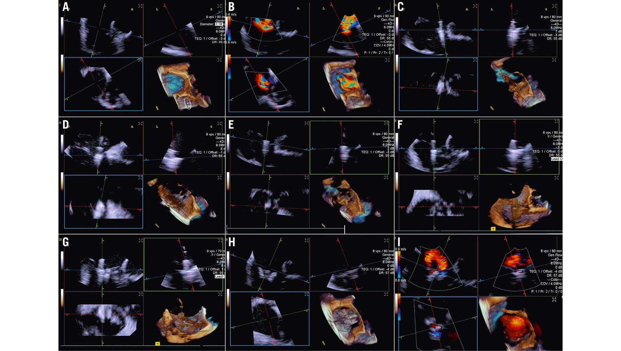
Figure 4. Three-dimensional ICE-guided tricuspid transcatheter edge-to-edge repair. A) 3D MPR ICE imaging planes with posterior and anterior leaflets in the TV home view (top left), septal leaflet and anterior/lateral grasping view (top right). The blue plane (bottom left) represents the short-axis (atrial en face) view of the TV leaflets. Finally, the corresponding 3D volume (bottom right; the aorta is at 5 o’clock). B) 3D colour MPR ICE imaging shows severe tricuspid regurgitation, allowing assessment of the number of regurgitation jets and jet location. C-E) The first device is advanced under the tricuspid valve. Clip orientation is optimised to be orthogonal to the coaptation line while the clip position is fine-tuned to the target location, and independent leaflet grasping is performed. F) 3D MPR assessment of second device orientation and location. G) 3D MPR assessment of third device orientation and location. H, I) 3D MPR and colour-flow Doppler final assessment of the devices. 3D: three-dimensional; ICE: intracardiac echocardiography; MPR: multiplanar reconstruction; TV: tricuspid valve
Transcatheter tricuspid valve replacement
TTVR is a new technology used for tricuspid regurgitation (TR) treatment in patients not eligible for other percutaneous approaches23. The suitability for this treatment mainly depends on the annular dimensions, and unlike other treatment approaches, the imaging quality requirements are not very strict24. Three-dimensional ICE plays a crucial role in guiding the TTVR procedure, especially when TOE imaging is technically challenging. There are currently some cases described in the literature in which TTVR procedures are performed using combined 3D TOE-ICE imaging. Furthermore, there are only a limited number of centres with experience in ICE-guided TTVR24, but considering the advantages of image quality, it could become the standard in the coming years. Typically, the ICE probe is inserted via transfemoral or transjugular access and positioned in the middle of the RA. By placing the 3D ICE probe directly in the RA, the problem of acoustic interference can be overcome. Furthermore, this position allows for stable visualisation of the TV and enables the acquisition of a 3D MPR by placing the region of interest over the TV annulus, creating a 3D en face view. The leaflet capture and the valve implantation can be guided stepwise with 3D MPR25. A dedicated echocardiographer is essential to create and optimise the imaging modalities (TOE and ICE). In fact, considering that intraprocedural echocardiographic guidance is essential for procedural success, the interventional imager plays a crucial role in guiding the implantation of the device. Figure 5, Figure 6 and Moving image 8 show a Cardiovalve case (Venus Medtech) and a LuX-Valve case (Jenscare Scientific).
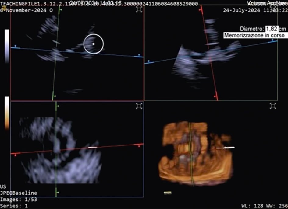
Figure 5. 3D MPR ICE imaging showing Cardiovalve device opening at the level of the tricuspid annulus. 3D: three-dimensional; ICE: intracardiac echocardiography; MPR: multiplanar reconstruction
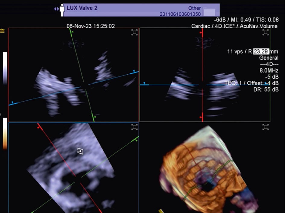
Figure 6. Three-dimensional MPR views of the tricuspid valve after LuX-Valve deployment. The atrial en face view allows the evaluation of possible residual leakage. MPR: multiplanar reconstruction
Mitral therapy
The use of ICE has been described for various mitral valve (MV) procedures, initially using 2D catheters and, more recently, RT 3D catheters, including mitral TEER with the MitraClip system17 and PASCAL system, as well as transcatheter mitral ViV implantation. Because experienced TOE operators can accurately image the MV due to the proximity of the oesophagus and the left atrium, insufficient imaging quality is less common in patients with MV disease than in those with TV disease.
Imaging the MV with ICE implies crossing the interatrial septum and positioning the imaging catheter in the left atrium, a step that can be technically challenging. The TSP is performed using simultaneous biplane imaging with the ICE catheter positioned in the middle of the right atrium and retroflexed towards the septum (Figure 7A). A preshaped stiff wire is carefully positioned into the upper left pulmonary vein under fluoroscopic and ICE guidance (Figure 7B). Predilatation of the septum is required to facilitate the advancement of the ICE catheter into the LA while tracking the trajectory of the wire (Figure 7B). This can be done either by advancing and retracting the TEER-guiding catheter or through preparatory balloon septostomy using a 12-14 mm over-the-wire percutaneous transluminal angioplasty balloon. Once the ICE catheter has been placed successfully into the left atrium, it is followed by the guiding sheath, and the implant itself is then advanced towards the diseased MV (Figure 7C). While the ICE catheter usually follows the curve of the delivery system, a position below it (Figure 7D) or the use of the right and left deflexion knob minimises shadowing artefacts and avoids direct interaction with the TEER device or any other catheter used for the intervention. The key advantage of RT 3D catheters is the ability to produce MPR that facilitates simultaneous optimisation of the trajectory and orientation in several planes and on the 3D view from the atrium (Figure 8, Figure 9A-Figure 9B-Figure 9C, Moving image 9-Moving image 10-Moving image 11). At the end of the procedure, closure of the interatrial septum should be considered (Figure 9D), since the defect is usually larger than after conventional TEER due to the manipulation of two catheters through the same access. Closure can be easily guided with the ICE catheter back to the right atrium (Figure 9E). Mini-TOE or a paediatric probe (without 3D capabilities), as well as transthoracic echocardiography26 are additional confirmatory imaging modalities that can be used in combination with ICE (Figure 9F).
Similarly, ICE can also be used to guide transseptal transcatheter procedures for mitral ViV and valve-in-ring replacement under conscious sedation27 (Moving image 12-Moving image 13). A minimalistic approach may have several advantages, including early discharge (possibly within 24 hours)28, and has been shown to offer similar safety compared to TOE guidance27.
Paravalvular leak (PVL) closure has also been performed using ICE29. While imaging from the right atrium might be sufficient for medial PVL, septum crossing may be mandatory when lateral PVL is involved.
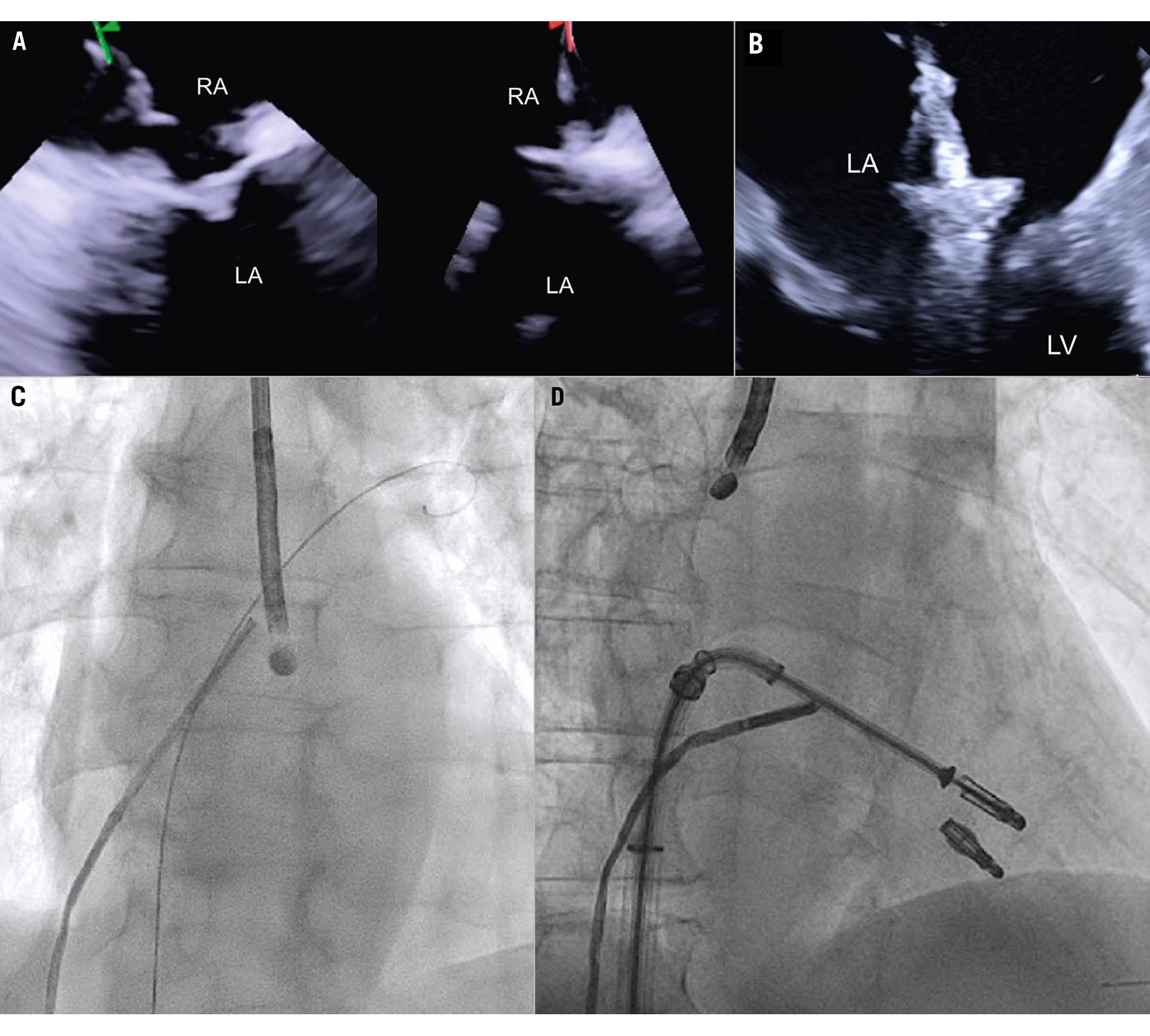
Figure 7. ICE-guided transseptal puncture. A) Transseptal puncture using biplanar imaging with the ICE catheter retroflexed in the middle of the RA. Needle tenting is seen simultaneously in two dimensions. B) Position of the delivery catheter over the diseased mitral valve. C) After wire placement and septum predilatation, the ICE catheter is moved into the LA following the trajectory of the stiff wire. A paediatric TOE probe without 3D capacity is inserted into the oesophagus. D) Position of the ICE catheter below the TEER system to avoid shadowing artefacts. 3D: three-dimensional; ICE: intracardiac echocardiography; LA: left atrium; RA: right atrium; TEER: transcatheter edge-to-edge repair
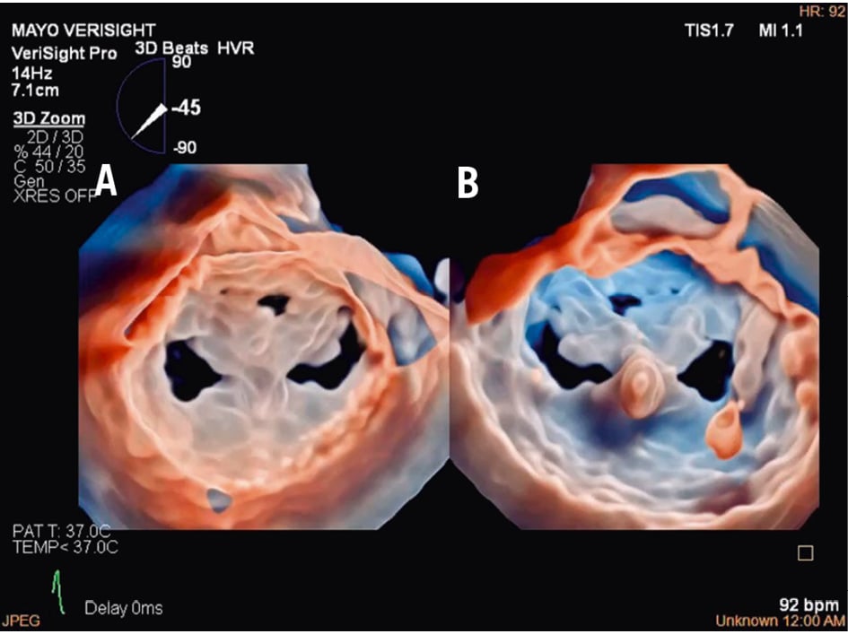
Figure 8. Three-dimensional true surgical view and left ventricular view of the mitral valve after TEER. A) 3D true surgical view; (B) left ventricular view. 3D: three-dimensional; TEER: transcatheter edge-to-edge repair
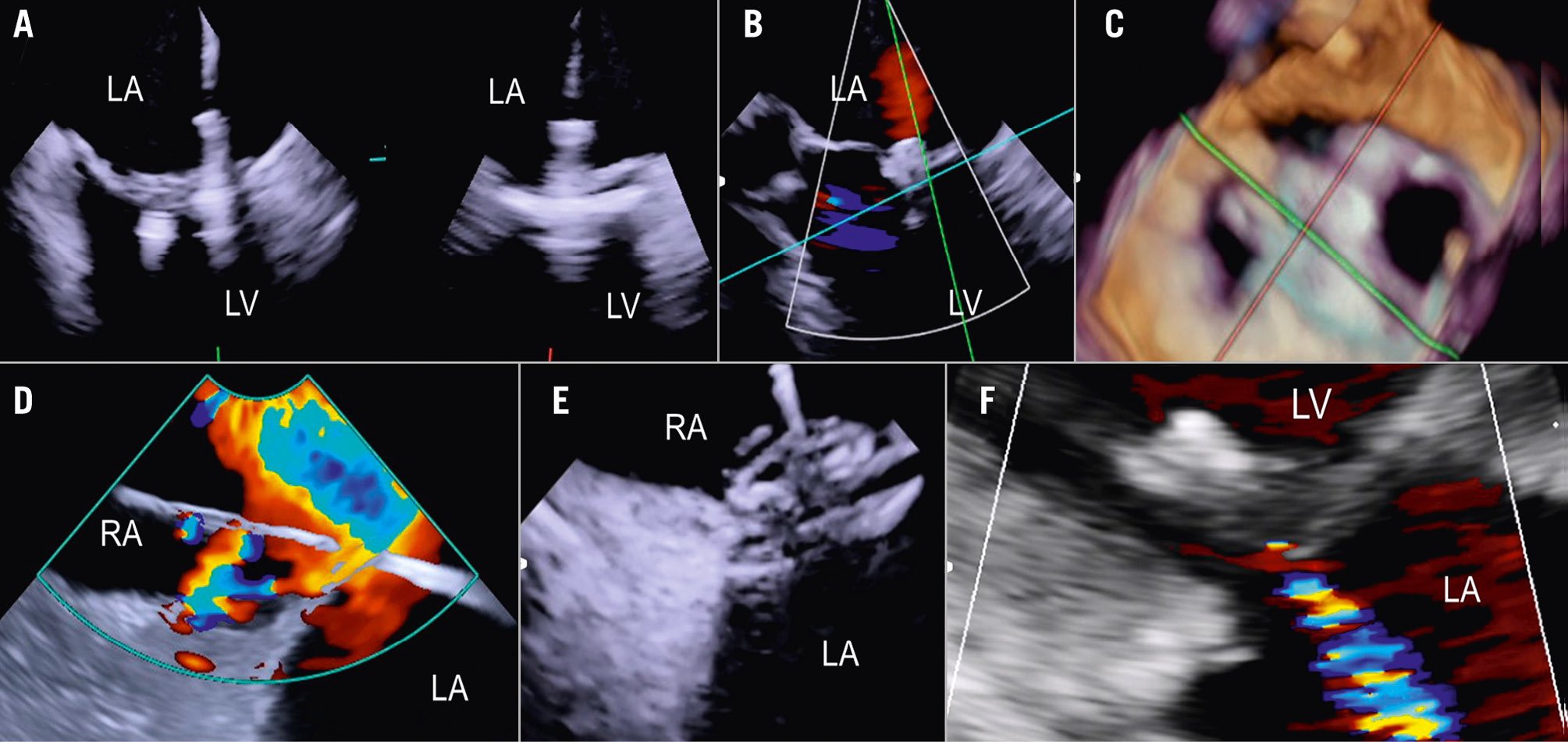
Figure 9. ICE-guided mitral valve transcatheter edge-to-edge repair. A) Implantation of two clips and leaflet capture under ICE visualisation; (B) final result after implantation of two clips for correction of a posterior flail; (C) 3D ICE view of the MV after implantation of two clips; (D) large iatrogenic ASD visualised from the right atrium and crossed by a wire; (E) ASD closure using a 14 mm Amplatzer Septal Occluder under ICE guidance; (F) final result with mild residual MR as shown by transthoracic echocardiography at discharge. 3D: three-dimensional; ASD: atrial septal defect; ICE: intracardiac echocardiography; LA: left atrium; LV: left ventricle; MR: mitral regurgitation; MV: mitral valve; RA: right atrium; RV: right ventricle
Non-valvular procedures
LAAO
In the majority of LAAO procedures, inferior and posterior transseptal punctures are needed to obtain coaxial alignment between the delivery system and the LAA central axis. When using 3D ICE, the probe is initially best positioned in the middle of the left atrium with a frontal view of the LAA. In comparison to the use of 2D ICE, 3D ICE enables reliable measurements of the LAA dimensions at a chosen depth by using the MPR function (Figure 10). Once the measurements have been taken, the ICE catheter can be placed in the left upper pulmonary vein, with a good view of the LAA structures and the left circumflex artery. After the LAA occluder is deployed, ICE can be used to check its positioning, anchoring, size/device compression, and sealing. All of these items can be checked with 3D ICE using fewer positions than with 2D ICE (Figure 11, Moving image 14-Moving image 15-Moving image 16-Moving image 17).
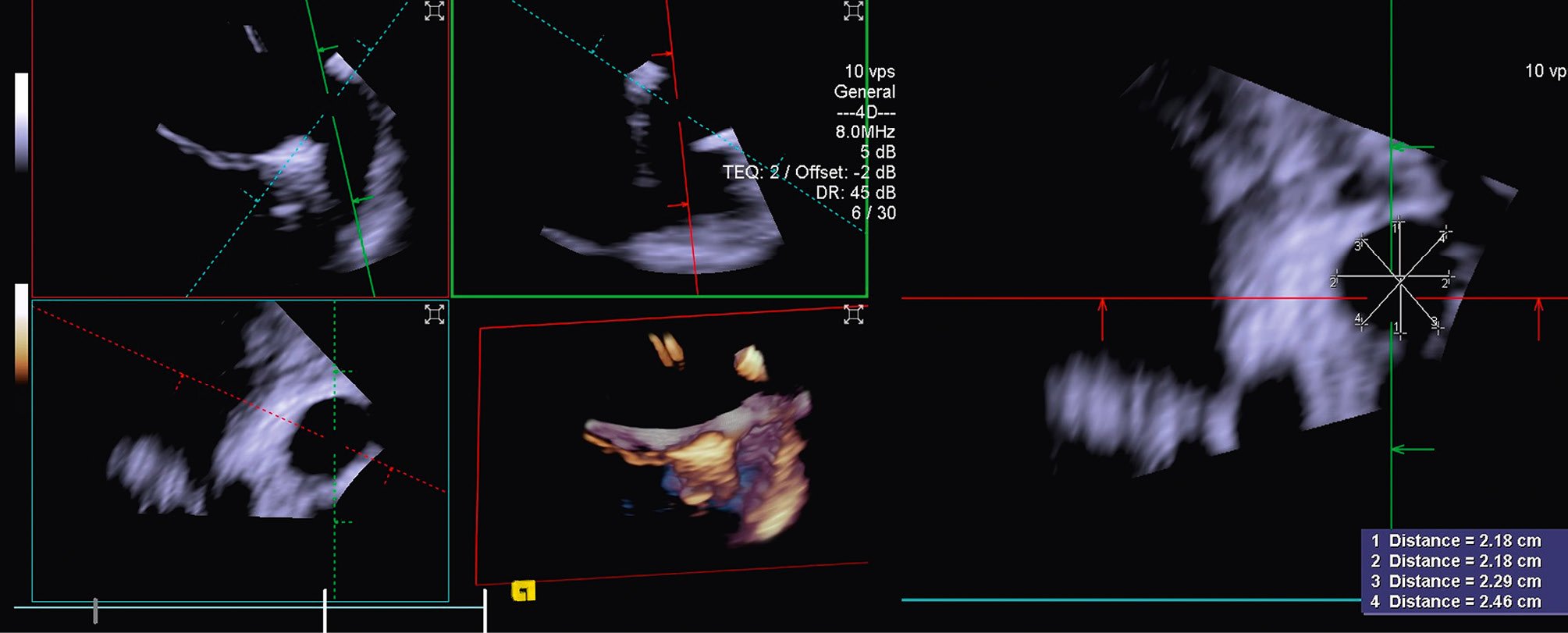
Figure 10. Three-dimensional MPR views showing the LAA orifice with its measurements. LAA: left atrial appendage; MPR: multiplanar reconstruction
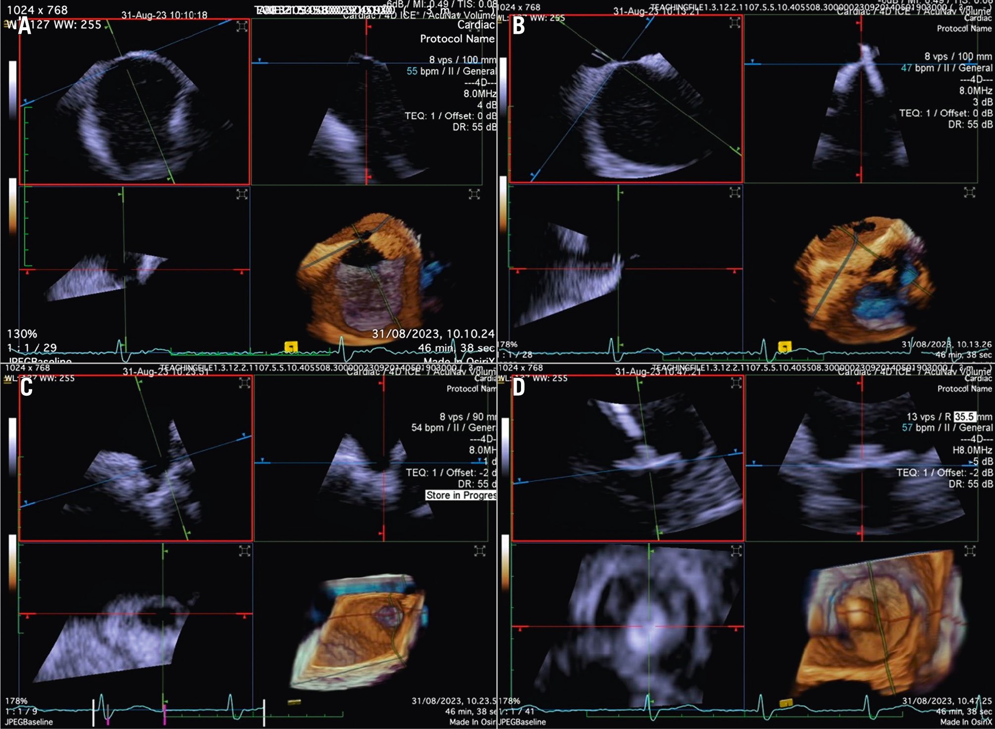
Figure 11. Three-dimensional ICE-guided LAA occlusion. A) 3D MPR with probe in the right atrium to identify the best position of transseptal puncture. B) 3D MPR in real time to assess the catheter crossing the interatrial septum. C) 3D MPR to identify the shape and morphology of the LAA. D) 3D MPR in real time during deployment allows for precise positioning of the device and assessment of the position, anchor, size, and seal. 3D: three-dimensional; ICE: intracardiac echocardiography; LAA: left atrial appendage; MPR: multiplanar reconstruction
PFO/ASD closure
Although PFO/ASD procedures can be performed using a simple 2D ICE probe, in some more challenging anatomical settings (e.g., floppy interatrial septum [IAS], doubt about PFO/small ASD, particular PFO tunnel), 3D ICE can be of added value. When 3D ICE is used for PFO or ASD procedures, positioning within the right atrium is sufficient. With 3D ICE, the septal defect can be visualised in a 3D volume and typically only a catheter position is needed. When starting the procedure, the operator should screen patients for additional septal defects that may have been missed on the preprocedural imaging and determine whether there is a floppy interatrial septum (for PFO) and a sufficient superior and inferior rim (for ASD). Three-dimensional ICE allows us to determine the size of the septal defect (especially for an ASD closure), guide occluder deployment, verify placement post-deployment, and screen for residual shunts1 (Figure 12, Figure 13, Moving image 18-Moving image 19-Moving image 20-Moving image 21-Moving image 22).
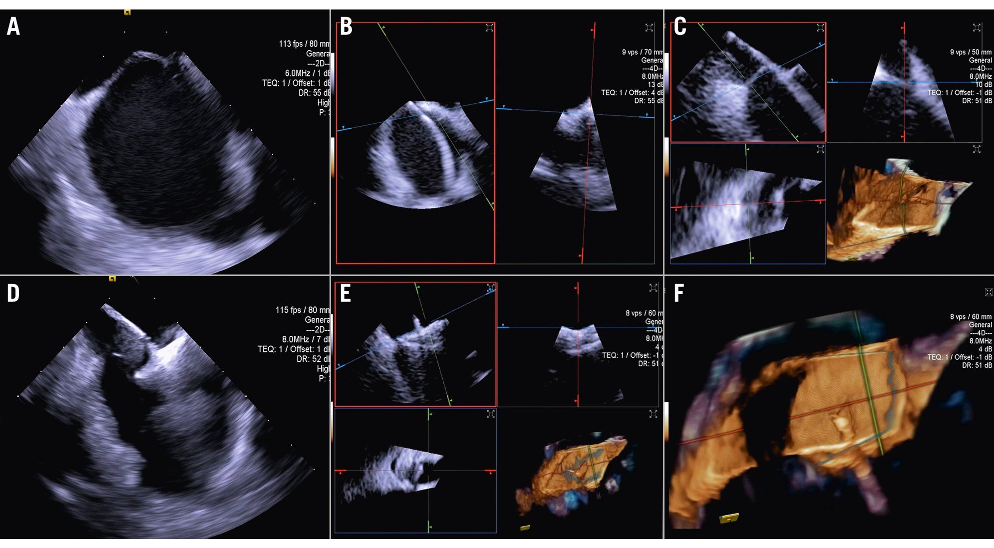
Figure 12. Three-dimensional ICE-guided patent foramen ovale closure. A) 2D imaging allowing assessment of needle tenting in the middle of the fossa ovalis. B) Biplane imaging allowing assessment of the catheter after crossing the septum in the superior-inferior and anterior-posterior positions simultaneously. C) 3D multiplanar reconstruction (MPR) allowing assessment of the catheter after crossing the septum. D) 2D imaging showing the deployment of the right disc of the device. E) 3D MPR allowing simultaneous assessment in the lateral, axial, and azimuthal planes of the right disc of the device. F) 3D reconstruction of the device. 2D: two-dimensional; 3D: three-dimensional; ICE: intracardiac echocardiography
Figure 13. Three-dimensional multiplanar reconstruction views of the device in the interatrial septum.
Training requirements
The manipulation of ICE catheters and the acquisition and interpretation of 3D ICE necessitate specialised training. To achieve these objectives, hands-on training using an animal model or a computer-based simulation tool is necessary to teach standard ICE positions and basic catheter movements inside the heart. Regardless of the training modality, standardised 3D ICE imaging protocols for each interventional procedure should be the foundation of these practical training events. Furthermore, clinical and procedural experience should be obtained under the direct supervision of expert physicians at high-volume centres. Finally, a case observation of an experienced interventionalist and imaging team can provide helpful insight into team dynamics, communication skills, and the shared vocabulary necessary for 3D ICE compared with TOE or 2D ICE. Operators should perform several simulated runs before using their skills in humans. The number of training sessions needed to achieve competence and confidence with 3D ICE technology is not established, and it is determined by the individual’s interventional and imaging background. The 2019 American College of Cardiology/American Heart Association/American Society of Echocardiography paper suggests a minimum ICE volume of ≥10 cases for Level III structural heart echocardiography competency30. However, defining minimum requirements may become possible as more data on the learning curve for various procedures become available.
Future directions and potential technology advancements
While 3D ICE has effectively addressed several challenges encountered with 2D ICE during SHD interventions, there are various technical limitations associated with the currently available catheters. These include limited steerability and stability while manipulating the device, challenges when switching between ICE and TOE on the same machine, and lower image resolution compared with TOE, especially with full-volume 3D modalities. Implementation is also challenging because of the variability in individual anatomy. Structured training programmes for how to effectively use ICE currently do not exist, thus operator experience plays a crucial role in successful implementation. Looking ahead, one can anticipate the development of various iterations of catheters aimed at enhancing steerability, while sterile stands will enhance procedural stability. Larger catheters featuring expanded matrix arrays hold the potential to enhance image resolution and 3D volume size, thus enabling comprehensive imaging of the entire heart from the right heart cavities using appropriately sized catheters for venous access. Progress in hardware and software may further enhance imaging quality during RT 3D MPR, as well as refine colour Doppler capabilities, enable operators to save 3D MPR presets, and enhance measurement precision. Integration of ICE into fusion-imaging platforms could facilitate catheter orientation and navigation within the heart. However, the most significant impact on ICE is likely to arise from the integration of artificial intelligence for image recognition, potentially leveraging data from computed tomography images to predict optimal imaging angles, optimise device positioning, and enhance procedural guidance31. Moreover, the incorporation of artificial intelligence, alongside robotic solutions for controlling ICE catheter movements, may enable precise and possibly independent catheter control through hand gestures and voice commands3233.
Conclusions
Three-dimensional ICE has become increasingly important in interventional cardiology, particularly for SHD, due to its unique ability to provide high-resolution images of the heart’s internal structures. This capability offers several key advantages that make 3D ICE an essential tool for guiding and executing SHD interventions, especially in patients where TOE might be contraindicated or provide inadequate imaging due to anatomical constraints. This document outlines the most recent technical advancements in 3D ICE technology and provides strategies for different transcatheter procedures based on current clinical experience.
Acknowledgements
John Ferguson and Laura Sitler, independent medical writers/editors, provided organisational and editorial support but did not contribute to the content of this manuscript.
Conflict of interest statement
S. Berti is a proctor for Edwards Lifesciences, Abbott, and Boston Scientific. O. De Backer received consultant fees from Abbott, Siemens, and Boston Scientific; and has received speaker honoraria from Abbott, Siemens, and Boston Scientific. E. Ho received consulting fees from Edwards Lifesciences, Medtronic, Abbott, Shifamed, GE HealthCare, Philips, NeoChord, and Valgen. F. Kreidel has received speaker honoraria from Philips, Siemens, and GE HealthCare. A. Latib received consultant fees from Medtronic, Philips, Abbott, Edwards Lifesciences, and Boston Scientific. M. Mariani received consultant fees and speaker honoraria from Edwards Lifesciences. F. Praz received support from attending meetings and/or travel from Abbott, Edwards Lifesciences, Medira, Siemens Healthineers, and inQB8 Medical Technologies; and he received grants from Abbott. N.C. Wunderlich is a proctor for Abbott, Edwards Lifesciences, and LifeTech Scientific Corporation; she has received speaker honoraria from Abbott, Edwards Lifesciences, GE HealthCare, Philips, and Boston Scientific. R.S. von Bardeleben has received speaker honoraria from Siemens, Philips, Abbott, and Edwards Lifesciences; he conducted trials (unpaid) for Abbott, Edwards Lifesciences, Medtronic, and Jenscare; and he received a fiduciary role on the board of directors of the Heart Valve Society USA (unpaid). A. D’Agostino has no conflicts of interest to declare.
Supplementary data
To read the full content of this article, please download the PDF.
Moving image 1. 3D reconstruction of the atrial view of the tricuspid valve.
Moving image 2. 3D RT MPR ICE imaging planes with the TV home view (top left), septo-lateral grasping view (top right), short axis (atrial en face) view of TV leaflets (bottom left) and the corresponding 3D volume (bottom right) with the aorta at 5 o’clock.
Moving image 3. 3D RT MPR ICE showing severe tricuspid regurgitation.
Moving image 4. 3D RT MPR views of independent leaflet grasping.
Moving image 5. 3D RT MPR views showing T-TEER device after grasping.
Moving image 6. 3D RT MPR assessment of stability after deployment of three T-TEER devices.
Moving image 7. 3D colour RT MPR result following T-TEER.
Moving image 8. 3D MPR views and 3D MPR colour of the TV after LuX-Valve deployment. The atrial en face view (bottom left) allows evaluation possible residual leakage.
Moving image 9. 3D True View surgical view and left ventricular view of mitral valve after TEER.
Moving image 10. Biplane imaging showing the long-axis view on the left and the bicommissural view on the right after M-TEER device release.
Moving image 11. Colour biplane imaging showing the longaxis view on the left and the bicommissural view on the right after M-TEER device release, with mild-to-moderate residual regurgitation.
Moving image 12. 3D mitral surgical view showing a degenerated bioprosthetic valve.
Moving image 13. 3D mitral surgical view after a mitral valvein-valve procedure.
Moving image 14. 3D MPR with the probe in the RA to identify the best position for transseptal puncture.
Moving image 15. 3D RT MPR to assess the catheter crossing the interatrial septum.
Moving image 16. 3D RT MPR showing the structure of the LAA.
Moving image 17. 3D RT MPR during deployment allows for precise positioning of the device and assessment of its position, anchor, size, and seal.
Moving image 18. Biplane imaging allows assessment of the catheter after crossing the septum in superior-inferior and anterior-posterior positions simultaneously.
Moving image 19. 3D RT MPR allowing assessment of the catheter after crossing the septum.
Moving image 20. 3D MPR allowing the simultaneous assessment of the right disc of the device in the lateral, axial, and azimuthal planes.
Moving image 21. 3D MPR views of the device in the interatrial septum.
Moving image 22. Colour biplane imaging showing the device in the interatrial septum with no residual shunts.