Description
The Recover LP 2.5 is a microaxial blood pump inserted percutaneously in a peripheral artery (usually the femoral) and advanced into the left ventricle where its cannula is positioned across the aortic valve (Figure 1).
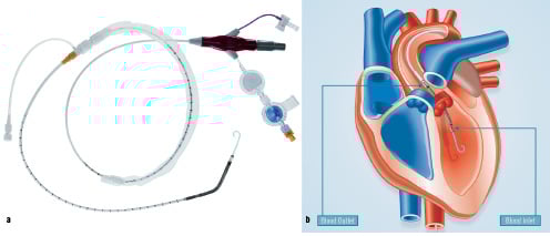
Figure 1. a) An overview of the Recover LP 2.5 pump. b) Pump positioning across the aortic valve.
The impeller draws blood from the cannula inlet on the ventricular side of the aortic valve, and expels it into the ascending aorta.
History
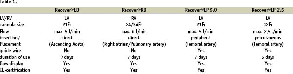
The innovative concept of a catheter-mounted left ventricular assist device was first conceived by Dr. Richard Wampler in 1975 and developed in the 1980’s as the Hemopump, a device with an extracorporeal drive shaft and motor. In the 1990’s, researchers at the Helmholtz Institute, (Aachen, Germany) advanced the concept of a catheter-mounted with a different design that became known as the Impella pump. After the introduction of a directly (open thorax) placed left ventricular support system, Recover LD, in June 2002, a directly placed system for the right side, Recover RD, was introduced in January 2003. The first version of the peripherally placed Impella pump Recover LP 5.0, which was introduced in January 2003 for clinical use, consisted of a 21F cannula/pump housing capable of flow rates of 5 L/min and required surgical cut-down for placement. In 2002 development of the LP 2.5 started and the CE marked device was launched in September 2004. By further reducing the size of the cannula down to 12 F (4mm), cut-down insertions are no longer necessary for the Recover LP 2.5, thus simplifying the insertion process. An overview of the pumps available and their specifications are depicted in Table 1.
Technical specifications
At the catheter’s most proximal end there is a plug, Figure 2, that connects the Recover LP 2.5 via an electrical extension line to an external drive console.
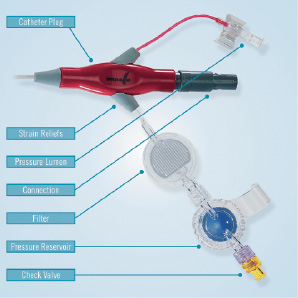
Figure 2. Catheter plug with integrated components.
The catheter plug also incorporates an integrated pressure sensor, an EEPROM for data storage, and Luer-connectors for the pressure sensor and purge fluid lumens. The purge fluid connector is comprised of a filter to prevent bacterial contamination, a pressure reservoir that maintains purge system pressure during change-out of the purge solution administration set, a check valve to prevent backflow and an air trap to prevent air entry into the system. The purge solution administration set is driven by a stand-alone syringe pump known as the Impella Purge Pump.
The catheter shaft supporting the pump is 9F and contains electrical wiring as well as the two fluid lumens to support the purge fluid and for pressure measurement. The shaft is marked to aid in positioning during device placement. A repositioning unit on the proximal end of the shaft incorporates a sluice with a haemostatic valve, to prevent bleed back, and an anti-contamination sleeve. The unit thus enables safe catheter manipulation during and after device placement Figure 1a.
Adjacent to the distal end of the 9F catheter is the electrical motor which drives the impeller, Figure 3.
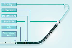
Figure 3. Distal end of the Recover LP 2.5 pump.
The brushless EC motor has an electrical power intake of approximately 15 watts at full flow. The outer diameter of the motor stator is 4mm. The motor rotor comprises a rare earth magnet which is mounted on a 1mm shaft. The impeller has an outer diameter of approx. 3.6 mm is moulded to the distal end of the shaft and it is invisible from the outside. The impeller is located distal to the motor while outlet is located between the motor and the impeller Figure 4.
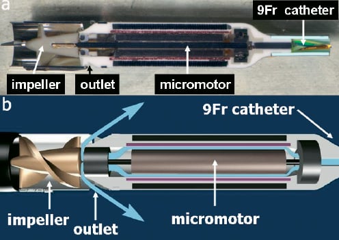
Figure 4. a) Cross-section of the micromotor and the impeller at the end of the 9Fr shaft. b) Schematic cartoon of the same structures. With high purge pressure blood is kept away from the internal motor parts (blue arrows).
The impeller design has undergone several iterations to optimize performance and reduce potential blood damage. For example, altering the shape of the impeller blades yielded reduced shear stresses, Figure 5.
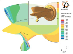
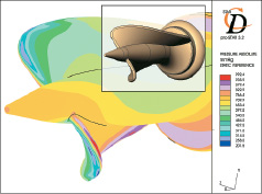
Figure 5. Computational fluid dynamic analysis to study impeller shear stresses on design iterations.
The impeller spins at up to 51 000 rpm providing 2.5 L/min of blood flow against physiological pressures.
Integrated on the cannula tip close to the outlet area is a pressure lumen which enables absolute pressure measurement to guide device placement. A pigtail is attached to the tip of the inlet area to stabilize the pump in its transvalvular position, Figure 3.
The Mobile Pump Console (MPC), weighing 3 kg drives the inserted pump, Figure 6a. The console allows users to interface with the system, controls the pump, monitors pump positioning, pump performance and purge pressures as well as the provision of alarm capabilities. An algorithm within the MPC utilizes the pressure sensor data along with the motor current to detect undesired pump issues (eg. misplacement, excess suction, etc.). The console assists the users in optimizing pump placement by means of pictograms, Figure 6b.
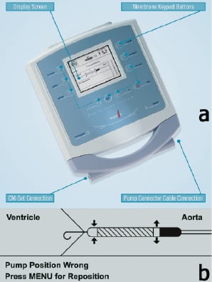
Figure 6. a) Mobile Pump Console (MPC). CM-Set Connection provides purge pressure signal. b) Example of MPC displayed pictogram indicating wrong device placement.
Additional peripheral equipment needed to utilize the Recover LP 2.5 includes a power supply unit and the Impella MPC cart.
Recover LP 2.5 is supplied with a complete introducer kit for the placement of the device, Figure 7.
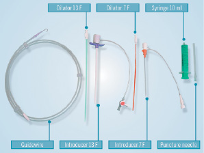
Figure 7. Introducer Kit.
An angiographic image of the pump in place across the aortic valve is depicted in Figure 8.
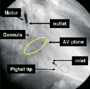
Figure 8. Angiographic image of the pump in place across the aortic valve (AV).
Tips and tricks/Technical considerations
1. The guide wire has to exit on the inner radius of the outlet area to avoid trapping while removing the wire once the pump is in the LV. By straightening the cannula the guide wire follows the inner radius automatically.
2. After placement across the aortic valve the pump should be operated at maximum performance level ‘P9’ to check for correct and stable positioning by x-ray and placement monitoring on the console. At high rotational speeds the pump has the tendency to suck itself into the ventricle. Therefore final adjustments should be done at target speed.
3. A repositioning of the device without x-ray guidance should only be performed at a lower performance level (P2) and always under guidance of the signals on the console. The console gives guidance to the user to perform the repositioning of the pump.
4. The pump may only be removed when set to performance level “P0”.
5. Very tortuous, diseased and calcified femoral or iliac arteries are a contraindication for the implantation of the device.
6. Closure of the puncture site with suture based devices such as the Prostar or double Perclose is recommended.
7. Indices of haemolysis should be measured every six hours throughout the period of device operation
Preclinical experience
Prior to the feasibility study in human at the end of 2003, the pump was tested in a series of eight animals end of 2002 that proved haemocompatibility and mechanical robustness of the device in-vivo. The issues of haemolysis and electrical safety have been extensively investigated in vivo.
Clinical experience
Impella keeps a product tracking database of all clinically used pumps. Due to the voluntary character of that product tracking the data may not completely reflecting the use of the device. According to that database 242 Recover LP 2.5 pumps have been used since market launch of the product in September 2004. Approximately 80% have been used electively in high-risk percutaneous procedures. The others 20% were in an emergency setting in patients with cardiogenic shock mainly in an acute myocardial infarction setting.