Magnetic wires, computarized navigation.
Abstract
Objective: The objective was to investigate the efficacy of a magnetic navigation system (MNS) in a coronary phantom.
Background: The number of coronary interventional procedures performed is steadily increasing with the availability of new devices to treat more complex lesions. Vessel tortuosity remains an important limiting factor in percutaneous coronary intervention.
Material and methods: The MNS can orient the tip of magnetized wire. The coronary phantom is a representation of the coronary tree. Two operators using both a magnetic wire and a standard wire, measured the procedural time (PT), the fluoroscopic time (FT) and the radiation exposure/area product (DAP) required to navigate through to fourteen segments. Ten wire advancements were performed per segment.
Results: In all but two segments, the PT was significantly longer using magnetic navigation than using manual navigation. The median FT in the left main artery (LMA) - first septal segment was 7 seconds vs. 18 seconds, with magnetic and manual navigation respectively, (p=0.05); in the LMA - obtuse marginal segment the median FT was 15 seconds with magnetic navigation vs. 29.5 seconds with manual navigation, (p=0.01); in the segment from proximal right coronary artery (RCA1) to the acute marginal branch, the median FT was 8 seconds with magnetic vs. 11 seconds with manual navigation, (p=0.05); and in the RCA1 -posterior descending segment the median FT was 9.5 seconds with magnetic vs. 15 seconds with manual navigation, (p=0.006).
Conclusion: The MNS facilitates wire access to distal segments in a coronary phantom, with a reduction in FT and radiation exposure using magnetic navigation in tortuous segments.
Introduction
The number of coronary interventional procedures is steadily increasing because the profile of new devices allows the interventionalist to more easily reach the distal bed of the coronary tree and the treatment of more complex lesions. While, access of distal lesions is less of an issue, vessel tortuosity might still hamper the success of percutaneous coronary intervention (PCI).
According to American College of Cardiology/American Heart Association (ACC/AHA)1 stenosis morphology classification, the failure of PCI depends on characteristics of the coronary lesion, in particular tortuosity, which is defined as moderate if the target lesion is located beyond two bends of >45 degrees and excessively tortuous if it is distal to 3 bends2.
The use of a magnetic navigation system (MNS) is a new option to reach distal lesions in a tortuous vessel. Magnetic navigation was first used in 1991 in a critically ill neonate with complex congenital heart disease3; since then it has been used in different medical areas such cranial neurosurgical procedures, orthopedic and head-and-neck surgery4,5. In interventional cardiology, endocardial mapping and radiofrequency catheter ablation was first performed in animals6 and more recently, in humans7.
The primary objective of this study was to investigate the efficacy of the magnetic navigation system in a simple three-dimensional coronary training phantom as a mandated experimental training exercise prior to the implementation of this technology in our catheterization laboratory. Furthermore, manual navigation was performed in order to control for some variables that might influence the results due to particular characteristics of the phantom, such as the distribution of the coronary arteries and the lack of lubricant.
Material and methods
Magnetic Navigation System
The Stereotaxis Niobe® Magnetic Navigation System (figure 1), consists of two permanent magnets, that are positioned on either side of the fluoroscopic table.
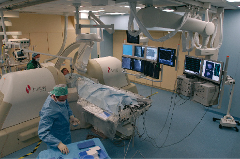
Figure 1. Photo of magnetic navigation room. The covered magnets are next to the patient.
The MNS generates magnetic fields of 0.08 Tesla, that are relatively uniform within a 15 cm volume within the chest of the patient. These magnets are mounted on mechanical positioners, and can be moved in three directions. They can rotate, translate and tilt with respect to each other creating an omnidirectional controllable magnetic field which can both orient in space and angulate the tip of magnetically enabled guidewires (figure 2).
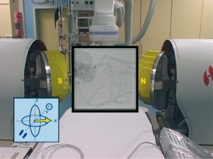
Figure 2. Bi-dimensional navigation. The picture shows the uncovered magnets positioned to direct the tip of the wire towards obtuse marginal.
All the above mentioned maneuvers are possible using a user interface that controls the physical movement of positioners using a vector that determines the orientation of the tip with the use of a computer mouse.
Magnetic guidewire
The Cronus™ floppy coronary guidewire with hydrophilic coating has a diameter of 0.014 in/0.36 mm, and nominal lengths of 180 and 300 cm. It has a flexible 2 cm distal coiled tip at the end of which is mounted a 2 mm gold cup within which a neodynium iron boron magnet resides.
These tiny magnets (3 mm long), when placed into the magnetic field generated by the MNS, align themselves in the direction of the applied magnetic field. Once the tip direction is changed, the magnetic wire is manually advanced until another change in direction is required.
Magnetic navigation procedure
The procedure starts conventionally, but once the guidewire is at the tip of the guiding catheter, a strategy of navigation must be chosen from four available options: (1) bi-dimensional, (2) three-dimensional, (3) vessel navigation or (4) using presets. 1. Bi-dimensional navigation allows the operator to change the orientation of the tip of the wire in a range of 360 degrees, like a clockface. For example, if 3 o’clock is chosen in the user interface, the tip of the wire points in that direction. This is the easiest way to start the procedure and is very intuitive (figure 2). 2. Three-dimensional navigation allows micronavigation whereby the orientation of the tip of the wire can be changed to any point in an hemisphere (figure 3).
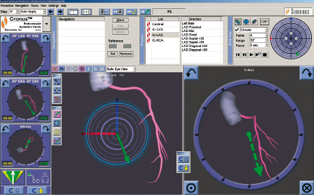
Figure 3. Three-dimensional navigation. In the upper right part of this picture there is a blue circle (bull’s eye), which represents an hemisphere, where you can point in any place inside of it, in order to choose the vector that follows the coronary anatomy. In this example the green point shows the operator’s choice. In the bottom of the screen, there are two big sections, the left one is the same bull’s eye, where the green arrow represents the resulting vector. The right one is the bi-dimensional view.
3. Vessel navigation involves acquiring, two reference images with an angular difference of at least 41 degrees, then a schematic drawing of the target coronary artery is obtained (figure 4).
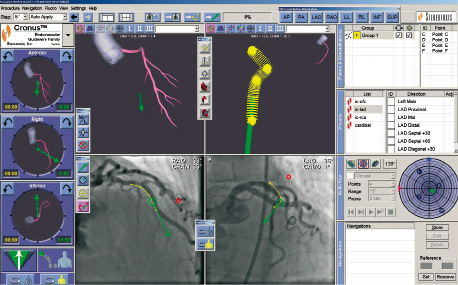
Figure 4. Vessel navigation. In the center of this picture there are four main sections, the upper right represents the navigation plan. In the coronary angiogram, that is shown in two views, there is a yellow line which correlates with the navigation plan. If you point to any place on the yellow line, the software automatically computes the vector necessary to align the tip of the wire to follow the anatomy of the coronary artery.
From the schematic the system computes a plan of navigation with all the vectors required to navigate through the coronary artery. The MNS saves these vectors, and when the physician points to the target point and MNS computes the best vector to reach the target point. 4. Lastly, presets are vectors previously defined from an anatomic model of the heart, the physician chooses in the menu the relevant vessel segment and the MNS automatically orientates the tip of the wire.
Coronary phantom and procedural technique
The three-dimensional coronary phantom has three main arteries that represent the left anterior descending (LAD), left circumflex (LCx) and right coronary artery (RCA) (figure 5).
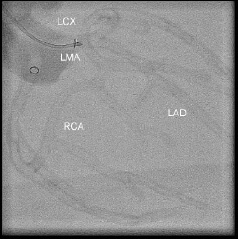
Figure 5. Glass coronary phantom. Three main arteries are represented. LAD refers to left anterior descending, LCx refers to left circumflex, RCA means right coronary artery and LMA means left main artery.
A 110 cm long 6-Fr guiding catheter was engaged into either the ostium of left main or the ostium of the RCA. We examined the procedural time, the fluoroscopic time and the radiation exposure/area product required to navigate through the different segments, using a magnetic and standard wire.
Fourteen coronary phantom segments were explored, five in the LAD, three in the LCx and six in the RCA. The navigation, either manual or magnetic, starts always at the ostium of the coronary artery for standardized timing and ten maneuvers were performed per segment using the same wire; then the radiation exposure, the procedural and fluoroscopic times were measured. Two operators (HGG and KT) were involved, both Interventional Cardiologists with similar training in conventional Interventional Cardiology procedures and also with similar training in MNS.
As a second step, a 3.5 x 12 mm stent was placed in the LAD at the bifurcation with the first diagonal branch, and the same measurements were done using magnetic navigation exclusively, navigating through the stent wall, across the ostium of the diagonal to enter the side branch.
Statistical analysis
Continuous data are presented as medians (first and third quartile values). Nonparametric Wilcoxon rank sum test were performed, as indicated. A two sided p value < 0.05 was considered statistically significant.
Results
The type of magnetic navigation was left to the operator’s discretion. The most common method used was bi-dimensional MNS.
Procedural time
As shown in table 1 and figure 6, in all but two segments, the procedural time with magnetic navigation was significantly longer than with manual navigation.
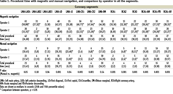
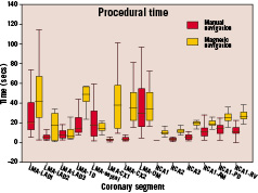
Figure 6. Procedural time box plot showing the comparison between manual and magnetic navigation.
Fluoroscopic time and radiation exposure/area product (DAP)
With magnetic navigation there was a marked reduction in fluoroscopic time and radiation exposure when trying to reach side branches compared to manual navigation (table 2, figure 7 and 8).
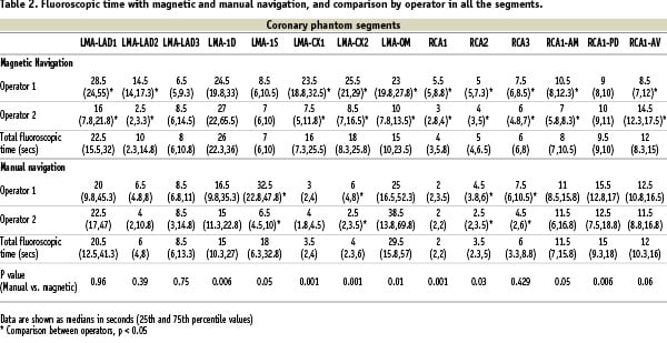
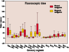
Figure 7. Fluoroscopic time box plot showing the comparison between manual and magnetic navigation.
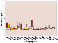
Figure 8. The box plot showing the differences in radiation exposure/area product (DAP) (Gym2) between manual and magnetic navigation.
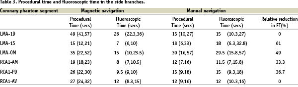
The relative reduction in fluoroscopic time ranged from 33.3% to 61% (table 3).
The median fluoroscopic time in the left main artery (LMA) – first septal (1S) segment was 7 seconds vs. 18 seconds, with magnetic and manual navigation respectively, (p=0.05); in the LMA – obtuse marginal (OM) segment the median was 15 seconds with magnetic navigation vs. 29.5 seconds with manual navigation, (p=0.01); in the coronary phantom segment from RCA1 to acute marginal (AM) the median fluoroscopic time was 8 seconds with magnetic navigation vs. 11 seconds with manual navigation, (p=0.05) and in the RCA1 - posterior descending (PD) segment the median fluoroscopic time was 9.5 seconds with magnetic vs. 15 seconds with manual navigation, (p=0.006).
Unlike manual navigation, during the repeated maneuvers, a trend towards a reduction in fluoroscopic time was observed with magnetic navigation in one of the operators in the three coronary arteries, but was more clearly seen in the LAD (figure 9).
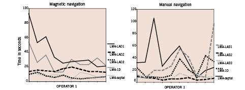
Figure 9. Learning curves. Operator 1 during repetitions had a trend to improve with magnetic navigation in left anterior descending. While with manual navigation the performance was unpredictable.
Performance in bifurcation
Magnetic navigation allows to reach the side branch across the stent struts in bifurcations in 10 out of 10 attempts. The median procedural time was 20 seconds and the median fluoroscopic time was 11 seconds.
Discussion
The three-dimensional glass coronary phantom used to test the ability to navigate the magnetized guidewire, represents a permanent road map, in contrast to real life procedures. This lack of a permanent road map in real life procedures is a major limitation to the current software.
We found that the procedural time using magnetic navigation was longer, and although statistically significant, in the worst case the largest difference was 57 seconds which in clinical practice is irrelevant. With manual navigation, fluoroscopic guidance is required from the beginning to the end of the procedure, since the direction of the tip of the wire cannot be predicted and advancement of the wire is achieved by trial and error, resulting in longer fluoroscopic time and higher radiation exposure compared to magnetic navigation.
The main use of magnetic navigation currently is to reach distal segments in tortuous vessels; in our model these segments are represented by side branches which take off from principal coronary arteries at angles of 45 degrees in the case of first diagonal and at 90 degrees first septal branch, obtuse marginal branch (LCx), acute marginal (RCA) and posterior descending artery. In these segments an important reduction in fluoroscopic time was observed.
Treatment of lesions in a tortuous vessel has been associated with a high incidence of emergency coronary artery bypass surgery because of the high rate of failure of PCI in these patients8. Furthermore, moderate and severe tortuosity significantly increase the fluoroscopic time9 and radiation dose in interventional procedures. Total radiation dose may be a limiting factor in prolonged procedures, because of debilitating skin injuries to the patient and long-term radiation effects remain a concern10.
In this experiment, we have demonstrated the feasibility of magnetic navigation to cross stent struts in bifurcations with short procedural and fluoroscopic times.
Magnetic navigation offers a real-time interactive opportunity to deal with tortuous vessels in contemporary practice, as the number and complexity of percutaneous coronary interventions increase. Its performance in clinical practice is being investigated.
Conclusion
The use of magnetic navigation in coronary phantom arteries with a magnetized coronary wire effectively facilitates access to distal segments. We have also documented a reduction in fluoroscopic time and radiation exposure in tortuous segments at the expense of a non-relevant increase in procedural time.
Acknowledgement
Dr García is supported by Sociedad Mexicana de Cardiología.